PISE 3400 A1 - Generator PARKSIDE - Free user manual and instructions
Find the device manual for free PISE 3400 A1 PARKSIDE in PDF.

| Brand | Parkside |
| Model | PISE 3400 A1 |
| Product type | Inverter generator |
| Continuous power (COP) (S1) | 2.8 kW (2800 W) |
| Maximum power (S2 5 min) | 3.4 kW (3400 W) |
| Rated voltage | 230 V~ |
| Frequency | 50 Hz |
| Rated current (230 V) | 12.2 A |
| Rated current (12 V) | 5.0 A |
| Engine type | 4-stroke, 1 cylinder, air cooling |
| Displacement | 212 cm³ |
| Max engine power | 3.7 kW / 5 HP |
| Fuel | Petrol Super E10 |
| Tank capacity | 7.4 L |
| Engine oil (type / quantity) | 15W40 / 600 ml |
| Spark plug | F7RTC |
| Battery type | Lead-acid |
| Battery capacity | 6.5 Ah |
| Weight | 38.5 kg |
| Sound pressure level (LpA) | 74.24 dB |
| Sound power level (LWA) | 94.0 dB |
| Protection class | IP23M |
| Operating modes | S1 (continuous), S2 (short duration) |
| Special features | Electric start (key and remote control), cable starter, digital display, ECO switch, overload protection, low oil shutdown, reset, 12 V DC socket |
| Warranty | 3 years |
Frequently Asked Questions - PISE 3400 A1 PARKSIDE
User questions about PISE 3400 A1 PARKSIDE
0 question about this device. Answer the ones you know or ask your own.
Ask a new question about this device
Download the instructions for your Generator in PDF format for free! Find your manual PISE 3400 A1 - PARKSIDE and take your electronic device back in hand. On this page are published all the documents necessary for the use of your device. PISE 3400 A1 by PARKSIDE.
USER MANUAL PISE 3400 A1 PARKSIDE
natural_image
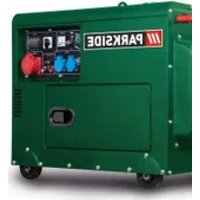
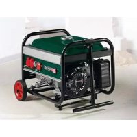
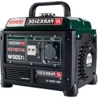
Exterior view of a Parkside electricity generator device (no visible text or symbols on body)
INVERTER GENERATOR 3400 W - PISE 3400 A1 INVERTER STROMERZEUGER 3400 W - PISE 3400 A1 GENERATEUR ELECTRIQUE INVERTER 3400 W - PISE 3400 A1
GB E N I CY MT ○ ○
INVERTER GENERATOR 3400 W
Operating and Safety Instructions
Translation of Original Operating Manual
FR BE
GÉNÉRATEUR ÉLECTRIQUE INVERTER 3400 W
Before reading, unfold the page containing the illustrations and familiarise yourself with all functions of the device.
DE AI CH
GB / IE / NI / CY / MT Operating and Safety Instructions Page 01
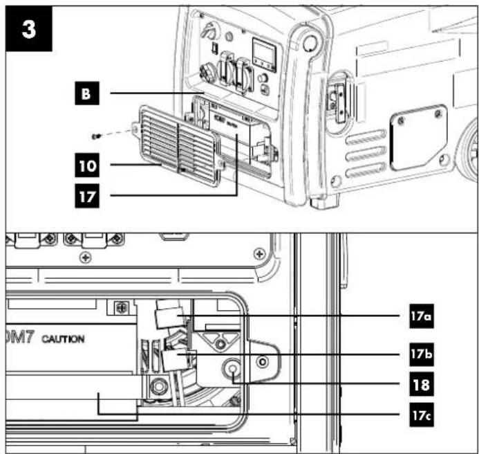
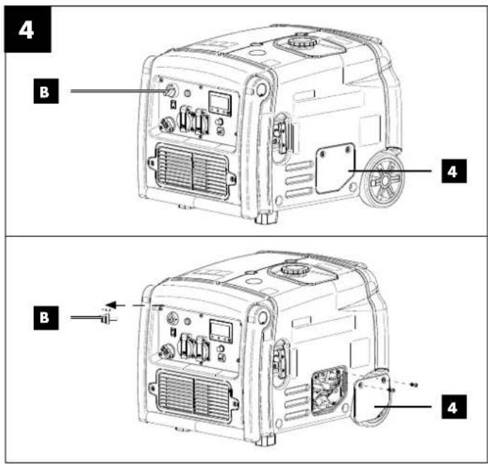

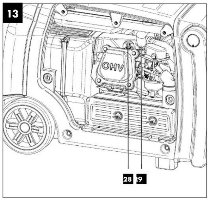
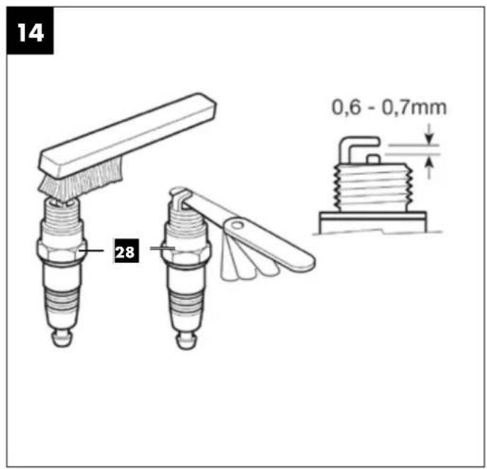
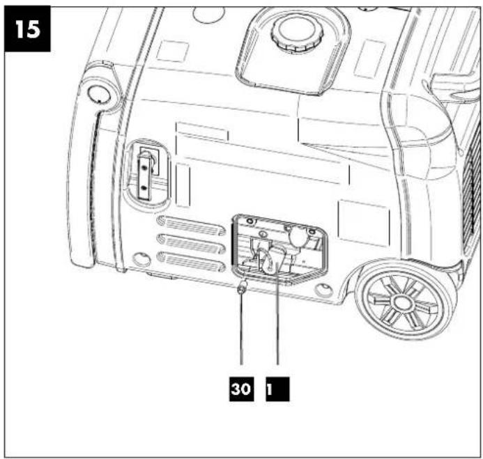
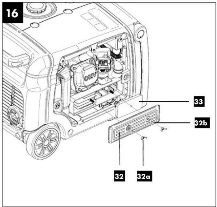
Table of contents: Page:
- Explanation of the symbols on the device....2
- Introduction......4
- Device description (Fig. 1 - 16)....4
- Scope of delivery 4
- Proper use....5
- Safety instructions....5
- Technical data....7
- Unpacking....7
- Before commissioning....8
- Operation....9
- Cleaning....10
- Maintenance....10
- Storage....12
- Transport....13
- Disposal and recycling 13
- Troubleshooting....14
- Warranty certificate....15
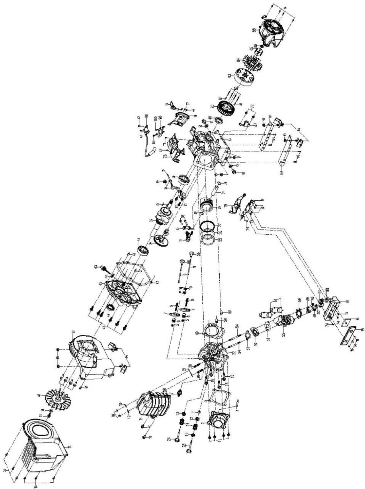
- Exploded view....110
- Declaration of conformity....112
1. Explanation of the symbols on the device


Attention! Failure to observe the safety signs and warning information affixed to the device and failure to observe the safety and operating manual can result in serious injury or even death.

Before commissioning, read and observe the operating manual and safety instructions!

Wear hearing protection!

Wear work gloves!

Do not expose the device to rain.
Naked flames or smoking near the device is strictly prohibited!
Warning - Hot parts!
Warning against electrical voltage.
Make sure that other persons maintain a sufficient safety distance. Keep uninvolved persons away from the device.
Attention: hot surface! Danger of burning.
Switch the engine off before carrying out any cleaning or maintenance work. Disconnect the spark plug connector from the spark plug and take out the ignition key.
Danger of poisoning! Only use the device outdoors and never in closed or poorly ventilated rooms.
 | Sparks are produced when the engine is started. These can ignite nearby flammable gases. |
 | Read the whole text of the operating manual through carefully before start up! |
 | Important. Always switch off the engine before refuelling. Do not refill during operation. |
 | Guaranteed sound power level of the device. |
 | Be very careful when dealing with fuels and lubricants! |
 | Check the oil level. |
 | The device complies with the applicable European directives. |
 | Device fuse |
 | Protection class II |
| DANGER! | Signal word to indicate an imminently hazardous situation which, if not avoided, will result in death or serious injury. |
| WARNING! | Signal word to indicate a potentially hazardous situation which, if not avoided, could result in death or serious injury. |
| CAUTION! | Signal word to indicate a potentially hazardous situation which, if not avoided, could result in minor or moderate injury. |
| NOTE | Signal word to indicate a potentially hazardous situation which, if not avoided, could result in product or property damage. |
2. Introduction
Manufacturer:
Scheppach GmbH
Günzburger Straße 69
D-89335 Ichenhausen
Dear Customer,
we wish you much pleasure and success in working with your new device.
Note:
In accordance with the applicable product liability laws, the manufacturer of this device assumes no liability for damage to the device or caused by the device arising from:
- Improper handling,
- Failure to comply with the operating instructions,
- Repairs carried out by third parties, unauthorised specialists,
• Installing and replacing non-original spare parts,
• Application other than specified.
Note:
Read the whole text of the operating manual before assembly and commissioning.
This operating manual should help you to familiarise yourself with your device and to use it for its intended purpose.
The operating manual includes important instructions for safe, proper and economic operation of the device, for avoiding danger, for minimising repair costs and downtimes, and for increasing the reliability and extending the service life of the device.
In addition to the safety instructions in this operating manual, you must also observe the regulations applicable to the operation of the device in your country.
Keep the operating manual at the device, in a plastic sleeve, protected from dirt and moisture. They must be read and carefully observed by all operating personnel before starting the work. The device may only be used by personnel who have been trained to use it and who have been instructed with respect to the associated hazards.
In addition to the safety instructions in this operating manual and the separate regulations of your country, the generally recognised technical rules relating to the operation of such machines must also be observed.
We accept no liability for accidents or damage that occur due to a failure to observe this manual and the safety instructions.
3. Device description (Fig. 1 - 16)
- Sight glass for fuel
- Fuel filler cap
- Pull starter
- Cover
- Wheels
- Earthing screw
- 12 V DC. Circuit breaker
- 12 V DC connection
- 230 V \~ - socket (2x)
- Battery compartment cover
- Fuel valve
- Folding transport handle
- Energy-saving switch (ECO)
- Ignition lock
- "RESET" button
- Display
- Battery
17a. Battery connection cable
17b. Engine connection cable
17c Battery bracket - Pairing button
- Oil dipstick
- Fuel filter insert
- Fuel tank
- Handle
- Oil warning indicator
- Overload indicator
- Operating display
- Display button
- Engine cover
- Spark plug
- Spark plug connector
- Oil drain screw
- Oil drain plug
- Air filter cover
32a. Wing nut
32b. Washer - Air filter
4. Scope of delivery
A Power generator/inverter
B Ignition key (2x)
C Radio remote control (2x)
D Spark plug wrench
E Adapter cable with 12V terminals
F Phillips screwdriver
G Oil filler bottle
5. Proper use
The power generator/inverter is suitable for devices that are intended to operate on a 230 V\~AC voltage source. With household devices and electronic devices, please check the suitability according to the respective manufacturer's specifications.
The power generator/inverter may only be used in the intended manner. Any use beyond this is improper. The user/operator, not the manufacturer, is responsible for damages or injuries of any type resulting from this.
An element of the intended use is also the observance of the safety instructions, as well as the assembly instructions and operating information in the operating manual.
Persons who operate and maintain the power generator/inverter must be familiar with the manual and must be informed about potential dangers.
In addition, the applicable accident prevention regulations must be strictly observed.
Other general occupational health and safety-related rules and regulations must be observed.
The liability of the manufacturer and resulting damages are excluded in the event of modifications of the power generator/inverter.
Please note that our equipment was not designed with the intention of use for commercial or industrial purposes. We assume no guarantee if the device is used in commercial or industrial applications, or for equivalent work.
6. Safety instructions
We have marked points in the operating manual that impact your safety with this symbol: ⚠
Furthermore, the operating manual contains other important text sections that are marked with the word "ATTENTION!".
Attention!
When using equipment, several safety warnings must be observed to prevent injuries and damage. For this reason, please carefully read this operating manual / safety instructions. If you hand the device over to another person, please hand over this operating manual / safety instructions as well. We accept no liability for accidents or damage that occur due to a failure to observe this manual and the safety instructions.
⚠️ DANGER
A failure to observe these instructions poses an extreme danger of death or the risk of life-threatening injuries.
⚠ WARNING
A failure to observe these instructions poses a danger of death or the risk of serious injuries.
CAUTION
A failure to observe these instructions poses a minor to moderate danger of injury.
NOTE!
A failure to observe these instructions poses a risk of damage to the engine or other property.
1) It is prohibited to make any modifications to the power generator/inverter.
2) The manufacturer's preset speed must not be changed. Power generator/inverters or connected devices may be damaged.
3) Danger of poisoning! Exhaust gases, fuel and lubricants are poisonous, exhaust gases may not be inhaled.
4) Fire risk! Petrol and fuel vapours are highly flammable or explosive.
5) Engine exhaust gases are toxic. The power generator/inverter must not be operated in unventilated rooms. If the power generator/inverter is to be operated in well-ventilated rooms, the exhaust gases must be discharged directly outside via an exhaust gas hose. Additional requirements for protection against fire and explosion must also be observed. Toxic exhaust gases can also escape when operating an exhaust hose. Because of the risk of fire, the exhaust hose must never be directed at flammable materials.
6) Never operate the power generator/inverter in rooms with highly flammable substances.
7) Hot surfaces! Danger of burns, do not touch exhaust system and drive unit.
8) Do not touch any mechanically moving or hot parts. Do not remove any protective covers.
9) Protective equipment! Use suitable hearing protection when you are near the device.
10) Only original parts may be used for maintenance and accessories.
11) Repair and adjustment work may only be carried out by authorised specialist personnel.
12) Protect yourself from electrical hazards.
13) Never touch the power generator/inverter with wet hands.
14) Only use approved and appropriately identified extension cables for use outdoors (H07RN).
15) If extension leads or mobile distribution networks are used, the resistance value must not exceed 1.5 Ω. As a guideline value, the total length of lines for a cross-section of 1.5 mm² should not exceed 60 m, and for a cross-section of 2.5 mm², 100 m should not be exceeded.
16) Never operate the power generator/inverter during rain or snowfall.
17) Always switch off the engine during transport and refueling.
18) Fuel is combustible and highly flammable. Do fuel the unit during operation. Do not fuel the unit when someone is smoking or near open flames. Do not spill any fuel.
19) Do not refuel or empty the fuel tank near open light, fire or flying sparks. Smoking prohibited!
20) Do not use the power generator/inverter in a thunderstorm. - Danger of lightning strike!
21) Provide a secure, level place for the power generator/inverter. Turning and tilting or changing location during operation are forbidden.
22) Place the power generator/inverter at least 1 m away from walls or connected devices.
23) Children must be protected by ensuring that they stay a safe distance away from the power generator/inverter.
24) Some parts of the reciprocating internal combustion engine are hot and may cause burns. The warnings on the power generator/inverter must be observed.
25) Values specified in the technical data under sound power level ( L_WA ) and sound pressure level ( L_FA ) represent emission levels and are not necessarily safe working levels. Since there is a correlation between emission and exposure levels, it cannot be reliably used to determine any additional precautionary measures that may be required. Factors influencing the current exposure level of the worker include the characteristics of the workspace, other noise sources, airborne noise, etc., such as the number of power generator/inverters and other adjacent processes and the length of time an operator is exposed to the noise. The permitted exposure level may also vary from country to country. Nevertheless, this information will enable the operator of the power generator/inverter to make a better assessment of the risks and hazards. If necessary, acoustical measurements should be taken after installation to determine the sound pressure level.
26) Warning! Comply with the electrical safety regulations applicable to the place where the power generator/inverters are used.
27) Warning! Consider the requirements and precautionary measures in case of re-supply of a system by power generator/inverters depending on the protective measures of this system and the applicable directives.
28) Inverter power generators should only be used up to their rated power under the rated ambient conditions. If the power generator/inverter is used in conditions that do not comply with the reference conditions according to ISO 8528-8:2016, 7.1, and if the cooling of the engine or generator is impaired, e.g. as a result of operation in restricted areas, a reduction in power is required.
29) Due to high mechanical loads, only durable rubber hose lines (per IEC 60245-4) or equivalent equipment should be used.
30) Observe the electrical safety regulations applicable to the place where the power generator/inverter is used.
31) Consider the requirements and precautionary measures in case of re-supply of a system by power generator/inverters depending on the protective measures of this system and the applicable directives.
Electrical safety
- Prior to use, the generator and its electrical equipment (including lines and plug connectors) should be checked to ensure that there are no defects.
-
The power generating unit must not be connected to another power source such as the power supply of energy supply companies. In special cases where a reserve connection to existing electrical systems is provided, this must only be carried out by a qualified electrician who will take into account the differences between the operated equipment using the public mains and operation of the power generating unit. According to this part of ISO 8528, the differences in the operating manual must be specified.
-
Protection against electric shocks depends on the circuit breakers which are matched precisely to the power generating unit. If a circuit breaker must be replaced, this should be done using a circuit breaker with the same rating and performance characteristics.
ATTENTION: Use only E10 unleaded petrol as fuel.
⚠ Use of petrol
⚠ Danger to life! Petrol is toxic and highly flammable.
- Only store petrol in containers (canisters) designed and tested for this purpose. The fuel tank caps must always be properly screwed on and tightened. Defective caps must be replaced for safety reasons.
- Keep petrol away from sparks, open flames, permanent flames, heat sources and other sources of ignition. Do not smoke!
- Refuel outdoors only and do not smoke while refuelling.
- Before refuelling, switch off the combustion engine and let it cool down.
- Petrol must be filled before starting the combustion engine. While the combustion engine is running or if the device is hot, the fuel tank must not be opened and petrol must not be filled.
- Open the fuel filler cap carefully and slowly. Wait for the pressure to equalise and only then remove the fuel filler cap completely.
- Use a suitable funnel or filler pipe for refuelling so that no fuel can spill onto the combustion engine and housing or lawn.
Do not overfill the fuel tank!
- To leave room for the fuel to expand, never fill the fuel tank beyond the lower edge of the filling nozzle. Observe additional information in the combustion engine user manual.
- If petrol has overflowed, do not start the combustion engine until the petrol-contaminated area has been cleaned. Avoid starting the engine until the fuel vapours have evaporated (wipe dry).
• Always wipe up spilled fuel immediately. - If petrol has got on clothing, it must be changed.
- The tank cover must be properly screwed on and tightened after each refuelling operation. The device must not be put into operation without the original tank cover screwed on.
- For safety reasons, check the fuel line, fuel tank, fuel filler cap and connections regularly for damage, ageing (brittleness), tight fit and leaks, and replace if necessary.
- Only empty the fuel tank outdoors.
- Never use beverage bottles or similar to dispose of or store operating materials, such as fuel. People, especially children, could be tempted to drink from it.
- Never store the device with petrol in the fuel tank inside a building. Any fuel vapours produced can come into contact with naked flames or sparks and ignite.
- Do not place the device and fuel tank near heaters, radiant heaters, welding machines or other sources of heat.
Risk of explosion!
If a defect is detected on the fuel tank, the fuel filler cap or on fuel-carrying parts (fuel lines) during operation, the combustion engine must be switched off immediately. Then consult a specialist dealer.
Battery safety
- To avoid spark formation due to a short circuit, always disconnect the negative cable (-) from the battery first and reconnect it last.
- Never smoke during work on the battery. Always keep sparks, naked flames and other heat sources away from the battery.
- Special care must be taken when using jumper cables. Follow relevant instructions to avoid damage to the device (in particular, do not operate the starter for more than 10 seconds).
- Never open the battery and do not drop it.
- Always charge the battery in a closed room with good ventilation, dry and protected against the weather.
- Do not short-circuit battery connections.
- Deformed or defective (leaking) batteries must not be used and must be replaced and disposed of in an environmentally friendly manner. Observe the country-specific regulations.
- If the batteries are defective, liquid may leak out. Avoid contact! In case of accidental contact, rinse with water. If the liquid gets into your eyes, seek additional medical attention. Leaking battery fluid can cause skin irritation, burns and chemical burns.
- Regularly visually inspect the connection cables on the battery for damage. Have damaged cables replaced by a specialist.
- Never bypass the fuses. Never use a fuse with a rating other than the prescribed rating (amperes).
Residual risks
The device is state-of-the-art and has been built in accordance with the recognised technical safety rules. However, individual residual risks can arise during operation.
- Health hazard due to electrical power, with the use of improper electrical connection cables.
• Furthermore, despite all precautions having been met, some non-obvious residual risks may still remain. - Residual risks can be minimised if the "Safety Instructions" and the "Intended Use" together with the operating manual as a whole are observed.
- Avoid accidental start-ups of the power generator/inverter.
- Use the device in the way that is recommended in this operating manual. This is how to ensure that your power generator//inverter provides optimum performance.
7. Technical data
Power generator ......Digital Inverter
Protection class IP23M
Continuous output P_n (COP) (230 V) (S1)....2.8 kW
Max. power P_max (230 V) (S2 5min)....3.4 kW
Rated voltage U_n 230 V \~
Rated current I n 12.2 A (230 V-)
Rated current I n 5.0 A (12 V)
Frequency F_n 50 Hz
Performance class....G2
Active power factor ....1
Quality class ......A
Drive motor design ....4-stroke, 1 cylinder, air-cooled
Displacement....212 cc
Max. power (engine) 3.7 kW/5 hp
Fuel....super E10 petrol
Fuel tank capacity 7.41
Engine oil type 15W40
Oil volume (approx.) 600 ml
Max. temperature....40°C
Max. installation altitude (above sea level) 1000 m
Spark plug.....F7RTC
Weight 38.5 kg
Battery type....Lead acid
Battery capacity 6.5 Ah
Subject to technical changes!
Operating mode S1 (continuous operation)
The power generator/inverter can be operated continuously with the specified power.
Operating mode S2 (short-term operation)
The power generator/inverter may only be operated at maximum power for a brief time.
Information about the noise level measured in accordance with applicable standards (EN ISO 3744:1995, ISO 8528-10:1998):
Sound pressure L_pA = 74.24 dB
Sound power level L_wA = 94.0 dB
Measurement uncertainty K_pA = 1.13 dB
Wear hearing protection.
Excessive noise can result in a loss of hearing.
8. Unpacking
- Open the packaging and carefully remove the device.
- Remove the packaging material, as well as the packaging and transport safety devices (if present).
- Check whether the scope of delivery is complete.
- Check the device and accessory parts for transport damage. In the event of complaints the carrier must be informed immediately. Later claims will not be recognised.
- If possible, keep the packaging until the expiry of the warranty period.
-
Familiarise yourself with the device by means of the operating manual before using for the first time.
-
With accessories as well as wearing parts and spare parts use only original parts. Spare parts can be obtained from your specialist dealer.
- When ordering, please provide our article number, the type and year of manufacture for your device.
⚠️ DANGER!
The device and the packaging are not children's toys!
Do not let children play with plastic bags, films or small parts! There is a danger of choking or suffocating!
9. Before commissioning
Electrical safety
Prior to use, the power generator/inverter and its electrical equipment (including lines and plug connectors) should be checked to ensure that there are no defects.
Never connect the power generator/inverter to the mains (socket).
The power lines to the consumer must be kept as short as possible.
⚠️ DANGER!
Risk of fire and explosion!
When filling, fuel may ignite and even explode. This can lead to severe burns or death.
- Switch off the engine and let it cool down.
- Keep heat, flames and sparks away.
- Only fill up with fuel outdoors.
- Wear protective gloves.
- Avoid contact with skin and eyes.
- Start the device at a distance of at least 3 m from the fuel filling point.
- Watch out for leaks. If petrol is leaking, do not start the engine.
⚠ WARNING!
Health hazard!
Inhaling petrol/lubricant vapours may lead to severe health damage, loss of consciousness and, in extreme cases, to death.
- Do not inhale petrol/lubricant vapours.
- Operate the device outdoors only.
NOTE!
Device damage
Using the device without or with too little engine and gearbox oil can result in engine damage.
- Fill with petrol and oil before commissioning. The device is supplied without engine oil and gearbox oil.
NOTE!
Environmental damage!
Spilled oil can pollute the environment permanently. The liquid is highly toxic and can quickly lead to water pollution.
- Fill/empty oil only on level, paved surfaces.
- Use a filling nozzle or funnel.
- Collect drained oil in a suitable container.
- Wipe up spilled oil carefully immediately and dispose of the cloth according to local regulations.
- Dispose of oil as per local regulations.
ATTENTION!
Check before operation
- Check all sides of the engine for oil or fuel leaks.
- Check the engine oil level.
- Check the fuel level – Fill with at least 7 litres of Super E10 petrol.
- Check the condition of the air filter.
- Check the condition of the fuel lines.
- Look for signs of damage.
- Check that all protective covers are in place and all screws are tightened.
- Ensure that the device is sufficiently ventilated.
- Make sure that the spark plug connector is attached to the spark plug.
- Disconnect any connected electrical devices from the power generator/inverter.
9.1 Earthing screw (6) (Fig. 1)
⚠ Attention! Electric shock!
- Do not use bare wires for earthing.
- Power generator/inverter must be safely earthed.
Earthing the housing is necessary to discharge static charging.
- To do this, connect a cable on one side to the earthing screw (6) of the power generator/inverter and on the other side to an external earth (e.g. earth rod).
9.2 Connecting the battery connection cable (17a) (Fig. 3)
- Remove the battery compartment cover (10) by removing the two screws with the enclosed Phillips screwdriver (F).
- Connect the battery connection cable (17a) to the engine connection cable (17b).
- Replace the battery compartment cover (10) and screw in the two screws.
9.3 Top up oil (Fig. 4, 5)
Attention!
The power generator/inverter is delivered without engine oil. Therefore, ensure that you add oil before starting it up. Use 15W40 oil here.
Note:
Check the oil level regularly before commissioning. An oil level that is too low can damage the engine. The oil warning system protects the power generator/inverter from damage caused by an oil level that is too low.
Before the minimum level is reached, the oil warning indicator (23) lights up and the system automatically switches off the engine (but the main switch is still set to REMOTE).
- Place the device on a level, even surface.
- Remove the ignition key (B) from the ignition lock (14).
- Remove the cover (4) by unscrewing the two screws with the Phillips screwdriver (F) provided.
- Unscrew the oil dipstick (19).
- Use the oil filler bottle (G) provided to top up the engine oil. Note the max. filling capacity of 600 ml. Carefully fill the oil up to the lower edge of the filling port.
-
Wipe the oil dipstick (19) with a clean, lint-free cloth.
-
Screw the oil dipstick (19) back into the filler neck until it reaches the stop.
- Pull the oil dipstick (19) out and read the oil level in the horizontal position. The oil level must be between L (low) and H (high) on the oil dipstick (19).
- If the oil level is too low, repeat the process.
- Then screw the oil dipstick (19) in again.
- Put the cover (4) on and fix in place by retightening the two screws.
9.4 Filling in fuel (Fig. 6)
Attention!
The power generator/inverter is delivered without petrol. It is therefore essential to fill with petrol before commissioning. Use Super E10 petrol for this.
- Unscrew the fuel filler cap (2). The fuel filler cap (2) is connected to an anti-loss device in the fuel tank (21) and thus cannot fall off.
- Use a suitable funnel (not included) to fill a maximum of 7.4 l of E10 unleaded petrol into the fuel tank (21).
- Ensure that the fuel tank (21) is not overfilled and that no petrol is spilled. Always use a fuel filter insert (20). Clean up spilled petrol immediately and wait until the fuel vapours have evaporated (wipe dry).
- Check the fuel sight glass (1) while filling in the fuel. The level must be between E (empty) and F (full). If the level falls below E, fill the fuel tank (21).
- Retighten the fuel filler cap (2).
ATTENTION!
Refuel in a well-ventilated area with the engine stopped.
If the engine was in operation immediately before, allow it to cool first. Never refuel the engine in a building where the fuel vapours may come into contact with flames or sparks.
Petrol is highly inflammable and explosive. When handling fuels, you may suffer burns or other severe injuries.
10. Operation
Starting the engine
⚠ Attention! Danger of poisoning!
- Only use the device outdoors and never in closed or poorly ventilated rooms.
Note: The energy saving switch (ECO) (13) must be set to "0".
Note: The battery (17) must be charged to start the power generator/inverter with the ignition key (B) or the radio remote control (C). Otherwise, the power generator/inverter must be started as described in section 10.3.
10.1 Starting the engine with the ignition key (B) (Fig. 7)
- Set the fuel valve (11) to the "ON" position.
- Insert the ignition key (B) into the ignition lock (14).
- Turn the ignition key (B) to the "START" position and hold it in this position until the device starts up.
- If the engine does not start even after several attempts, start the device as described in section 10.3.
10.2 Starting the engine with the radio remote control (C) (Fig. 8)
- Set the fuel valve (11) to "ON".
- Insert the ignition key (B) into the ignition lock (14).
- Turn the ignition key (B) to the "RUN/REMOTE" position.
- Now press the "ON" button on the radio remote control (C).
- If the engine does not start even after several attempts, start the device as described in section 10.3.
10.3 Starting the engine with the pull starter (3) (Fig. 9)
Attention! Never allow the pull starter (3) to whip back. This can result in damage.
- Set the fuel valve (11) to "ON".
- Insert the ignition key (B) into the ignition lock (14).
- Turn the ignition key (B) to the "RUN/REMOTE" position.
- Now pull the pull starter (3) and the engine should start. If the engine does not start, repeat the process.
- If the engine does not start even after several attempts, read the "Troubleshooting" chapter.
Note:
If the engine is being started for the first time, several tries are required to start until the fuel has been delivered from the fuel tank (21) to the engine.
Note: If the device's battery (17) is empty, the engine can only be started using the pull starter (3).
If the battery (17) is deeply discharged, proceed as described in sections 12.5 and 13.2.
10.4 Switch off the engine (Fig. 10)
Allow the power generator/inverter to run for a short time (approx. 30 seconds) without load before switching it off so that it can "cool down".
- Turn the ignition key (B) to the "STOP" position.
- Remove the ignition key (B) and store it in a safe place.
- Set the fuel valve (11) to the "OFF" position.
- Disconnect the power consumers from the device.
Note: You can only remove the ignition key (B) when the "STOP" position is selected.
10.5 Overload indicator (24) (Fig. 11)
The overload protection becomes active if the power consumption is too high and switches off the 230 V \~ sockets (9).
- Switch the device off as described in section 10.2.
- Disconnect the power consumers from the device.
10.6 Oil warning indicator (23) and automatic oil cut-off (Fig. 11)
The oil warning indicator (23) prevents the engine from starting if the oil level is too low. This protects the engine from damage.
If the oil level falls below the defined minimum level, the oil warning indicator (23) starts to light up red and the automatic oil shut-off switches off the power generator/inverter to prevent damage to the engine.
It is not possible to start the engine until the engine oil has been filled (see chapter 9.3).
10.7 Energy saving switch (ECO) (13) (Fig. 1)
Attention: The energy-saving switch (ECO) (13) is not suitable for applications in which a consumer requires a lot of energy very quickly.
The energy-saving switch (ECO) (13) can be used to limit fuel consumption and reduce noise when less power is needed.
- To do so, set the energy-saving switch (ECO) (13) to "1". The power generator/inverter now regulates the speed in accordance with the required power.
The energy saving switch (ECO) (13) must be set to "0" when electrical devices that require a high starting current are connected, for example a compressor. The energy saving switch (ECO) (13) must also be set to "0" initially when the power generator/inverter is started.
10.8 "RESET" button (15) (Fig. 1)
If the overload protection has been triggered and the overload indicator (24) lights up red, the "RESET" button (15) can restore the output power of the power generator/inverter. It is then not necessary to restart the engine.
- Press and hold the "RESET" button (15) for 1 second until the light (red) is extinguished and the operation indicator (25) (green) illuminates.
If the overload protection has not tripped, the RESET button (15) has no effect.
10.9 Display button (26) (Fig. 11)
The display (16) is active when the engine is running. You can use the display button (26) to alternate between displaying the following data:
- Engine speed
- Operating hours
- Output power
The display (16) switches itself off after approx. 20 seconds if not used.
10.10 Charging external devices (Fig. 1, 3) ⚠️ DANGER!
Danger due to incorrect charging.
- Plug the adapter cable with 12 V terminals (E) into the 12 V DC connection (8) provided for this.
11. Cleaning
Before carrying out any cleaning or maintenance work, switch off the engine and remove the ignition key (B) from the ignition lock (14). In addition, remove the spark plug connector (29) from the spark plug (28).
ATTENTION! Danger of burning! Wait until the device has cooled down before performing cleaning or maintenance work.
11.1 Cleaning
Keep protective devices, air vents and the engine housing as free of dust and dirt as possible. Rub the device clean with a clean cloth or blow it off with compressed air at low pressure. We recommend that you clean the device directly after every use.
Clean the device at regular intervals using a damp cloth and a little soft soap. Do not use any cleaning products or solvents; they could attack the plastic parts of the device. Make sure that no water can penetrate the device interior.
12. Maintenance
WARNING!
Always wear protective gloves and a mask during maintenance work!
12.1 Maintenance plan
Always comply with the following maintenance intervals in order to ensure problem-free operation.
ATTENTION! At initial start-up, engine oil and fuel must be filled.
| Before every use after operating for 20 hours after operating for 50 hours | after operating for 300 hours | ||
| Checking the engine oil X | |||
| Changing the engine oil X | |||
| Checking the air filter | X | Change filter insert if necessary | |
| Cleaning the air filter X | |||
| Visual inspection of the device | X | ||
| Cleaning the spark plug first time, then every | 50 hours | Gap: 0.6 - 0.7 mm, replace if necessary | |
| Check and readjust the throttle valve | X^* | ||
| Cleaning the cylinder head X^* | |||
| Adjust the valve play X^* | |||
| Attention: Only have points "X*" carried out by an authorised specialist company. | |||
12.2 Check the oil level (Fig. 4 + 5)
- Place the power generator/inverter on a level, even surface.
- Remove the ignition key (B) from the ignition lock (14).
- Remove the cover (4) as described in 9.3 (Fig. 4).
- Unscrew the oil dipstick (19).
- Wipe the oil dipstick (19) with a clean, lint-free cloth.
- Screw the oil dipstick (19) back into the filler neck until it reaches the stop.
- Pull the oil dipstick (19) out and read the oil level in the horizontal position. The oil level must be between L (low) and H (high) on the oil dipstick (19).
- Then screw the oil dipstick (19) in again.
- Put the cover (4) on and fix in place by retightening the two screws.
12.3 Changing oil (Fig. 4, 5, 15)
Change engine oil after 50 hours of operating time.
The engine oil change should be carried out while the engine is at operating temperature.
- Place the power generator/inverter on a level, even surface.
- Remove the ignition key (B) from the ignition lock (14).
- Remove the cover (4) as described in 9.3 (Fig. 4).
- Provide a suitable collection container (not included in the scope of delivery).
- Remove the oil drain plug (31) and remove the oil dipstick (19).
- Remove the oil drain screw (30) with a 10 mm open-ended spanner (not included in the scope of delivery) to allow the oil to drain off.
- Screw the oil drain screw (30) back in.
- Fill up with new engine oil (approx. 600 ml).
- Screw the oil dipstick (19) in again.
- Attach the oil drain plug (31) again.
- Put the cover (4) on and fix in place by retightening the two screws.
- Dispose of the used oil properly.
12.4 Air filter (33) (Fig. 12, 16)
NOTE!
Risk of damage!
Operating the engine without an air filter (33) or with a damaged air filter can cause engine damage.
- Never run the engine without the air filter (33) or with a damaged air filter. This would allow dirt into the engine, which would result in severe damage to the engine.
Clean the air filter (33) every 50 operating hours, replace if necessary.
- Remove the engine cover (27) by loosening the three screws with the Phillips screwdriver (F) provided (Fig. 12).
- Remove each of the two wing nuts (32a) and two washers (32b) on the air filter cover (32) (Fig. 16).
- Remove the air filter cover (32).
- Remove the air filter (33).
- Do not use harsh cleaners or petrol to clean the air filter (33).
- Clean the air filter (33) by knocking it on a flat surface. If heavily soiled, wash with soapy water, then rinse with clean water and allow to air dry.
- The re-assembly takes place in reverse order.
12.5 Charge the battery (17) with a car battery charger (Fig. 1, 3)
⚠️ DANGER!
Danger due to charging the battery incorrectly!
If the charging voltage is too high, there is a risk of the battery (17) exploding.
Always remove the ignition key (B) from the ignition (14) when working on the battery (17).
- The charging current of the battery charger must not exceed 5 A and the charging voltage must not exceed 14.4 V.
- Remove the battery (17) as described in Section 13.2.
- Connect the battery (17) to a suitable car battery charger. Then connect the red cable to the positive pole (+) and the black cable to the negative pole (-) of the charging unit.
- Charge the battery (17) for at least 5 hours.
Attention!
Danger of short circuit!
- To avoid a short circuit, always disconnect the negative cable (-) from the battery (E) first and reconnect it last.
- When connecting/disconnecting the battery connection cable (17a), make sure that the poles (+/-) do not touch each other and/or the frame.
12.6 Spark plug (28) (Fig. 12 - 14)
⚠️ ATTENTION: Only replace the spark plug when the engine is cold!
Check the spark plug (28) for contamination for the first time after 20 operating hours and clean it with a copper wire brush if necessary. Then service the spark plug (28) every 50 operating hours.
- Remove the engine cover (27) by loosening the three screws with the Phillips screwdriver (F) provided (Fig. 12).
- Pull off the spark plug connector (29) with a twisting motion.
- Remove the spark plug (28) with the enclosed spark plug wrench (D).
- Remove any dirt from the base of the spark plug (28).
- Visually inspect the spark plug (28). Remove any deposits present using a wire brush.
- Check the spark plug gap. Set the electrode gap to 0.6 to 0.7 mm with a feeler gauge.
- The re-assembly takes place in reverse order.
NOTE
A loose spark plug (28) can overheat and cause damage to the engine. Tightening the spark plug (28) too much can damage the thread in the cylinder head.
12.7 Cleaning the fuel filter insert (20) (Fig. 6)
Note: The fuel filter insert (20) is a filter cup which is located directly under the fuel filler cap (2) and filters all the fuel filled in.
- Unscrew the fuel filler cap (2). The fuel filler cap (2) is connected to an anti-loss device in the fuel tank (21) and thus cannot fall off.
- Remove the fuel filter insert (20). Clean it in a non-flammable solvent or a solvent with a high flash point.
- Reinsert the fuel filter insert (20).
- Retighten the fuel filler cap (2).
12.8 Pairing the new radio remote control (C) with the power generator/inverter (Fig. 3)
Note: The original radio remote control is already paired at the factory. A new radio remote control from the spare parts shop must be paired again. Pairing is not necessary when replacing
the battery!
- Insert the ignition key (B) into the ignition lock (14).
- Turn the ignition key (B) to the "STOP" position.
- Set the fuel valve (11) to the "OFF" position.
- Remove the battery compartment cover (10) by unscrewing the two screws with the Phillips screwdriver (F) provided.
- Press and hold down the pairing button (18).
- Turn the ignition key (B) to the "RUN/REMOTE" position.
- Now press the "ON" button on the radio remote control (C) for 2 seconds and then the "OFF" button for 1 second.
- Release the pairing button (18).
- Turn the ignition key (B) to the "STOP" position.
- Turn the ignition key (B) to the "RUN/REMOTE" position.
- Start the engine with the radio remote control (C) as described in section 10.2.
- If pairing the radio remote control (C) with the device did not work, repeat the procedure.
Please provide the following information in the event of any enquiries:
• Machine data - type plate
• Engine data - type plate
Important note in the case of repairs:
For return delivery of the device for repair, please ensure for safety reasons that it is free of oil and fuel when it is sent to the service centre.
12.9 Ordering spare parts
Please provide the following information when ordering spare parts:
- Device type
• Device article number
Service information
Note that the following parts on this device are subject to natural or usage-related wear, or that the following parts are required as consumables.
Wearing parts*: Spark plug, air filter
* may not be included in the scope of delivery!
Spare parts:
Radio remote control - article no.: 7906200701
Radio remote control battery type: CR1620
13. Storage
DANGER!
Risk of fire and explosion!
Storing the product near potential sources of ignition can result in a fire or an explosion. This can lead to severe burns or death.
- Eliminate possible sources of ignition, such as furnaces, hot water boilers with gas, gas dryers, etc.
NOTE!
Risk of damage!
If the product is not stored properly, the engine can be damaged.
- Store the product protected against dirt, dust and moisture.
13.1 Preparation for storage
- Empty the fuel tank (21) using a petrol extraction pump (see section 13.3). Warning: Do not remove the petrol in enclosed spaces, near fire or when smoking. Petrol fumes can cause explosions and fire.
- Carry out an oil change (see section 12.3).
- To do so, remove the used engine oil from a warm engine and refill with fresh oil.
- Remove the spark plug (28).
- Fill approx. 20 ml of oil into the cylinder with oil filler bottle (G) provided.
- Pull the pull starter (3) slowly so that the oil protects the inside of the cylinder.
- Screw the spark plug (28) back in.
- The ignition key (B) must always be removed from the ignition lock (14) and stored securely to prevent unauthorised or improper use by children and other persons.
- When the device is taken out of service for an extended period of time, before starting work on or near electrical components, disconnect the battery connection cable (17a) from the engine connection cable (17b). We recommend removing the battery (17) and storing it fully charged in a dry and locked room.
- Store the device in a well-ventilated place or area.
13.2 Removing the battery (17) (Fig. 1, 3)
- Remove the battery compartment cover (10) by unscrewing the two screws with the Phillips screwdriver (F) provided.
- Disconnect the battery connection cable (17a) and the engine connection cable (17b).
- Then loosen the two screws (16b) of the battery bracket (17c) with the Phillips screwdriver (F).
- Remove the battery (17).
- Pull the protective caps off both poles of the battery (17).
- Remove the two pole cables from the battery (17) with the enclosed Phillips screwdriver (F).
Ensure that batteries are secured against unauthorised use (e.g. by children).
Charge the battery (17) during the winter 1-2 times to ensure that the full charging capacity is maintained. Incorrect storage can damage the battery (17). In this case, the warranty is void.
13.3 Drain petrol with a petrol extraction pump (Fig. 13)
In the case of storage over a longer period of time, the petrol must be drained.
- Hold a collection container under the hose of the petrol extraction pump (not included in the scope of delivery).
- Unscrew the fuel filler cap (2). The fuel filler cap (2) is connected to an anti-loss device in the fuel tank (21) and thus cannot fall off.
-
Remove the fuel filter insert (20).
-
Push the hose of the petrol extraction pump into the fuel tank (21) and drain out the petrol completely using the petrol extraction pump.
- Reinsert the fuel filter insert (20).
- Retighten the fuel filler cap (2).
14. Transport
- Empty the fuel tank (21) using a petrol extraction pump (see section 13.3).
- If operational, keep the engine running until the remaining petrol has been used up.
- Drain the engine oil from the warm engine (see section 12.3).
- Remove the spark plug connector (29) from the spark plug (28).
- The power generator/inverter can be transported simply and easily using the trolley function. To do this, fold the transport handle (12) out and up and pull the device to the desired location.
- The device can be lifted and moved using the fold-out transport handle (12) and the fixed handle (22).
- Secure the device against slipping using a tension strap, for example.
15. Disposal and recycling
Notes for packaging


The packaging materials are recyclable. Please dispose of packaging in an environmentally friendly manner.
Notes on the electrical and electronic equipment act [ElektroG]
![PARKSIDE PISE 3400 A1 - Notes on the electrical and electronic equipment act [ElektroG] - 1](/content/2026/04/738782/images/823f24ab800522f58fedea51b16368608a5a468a345c881d1ddc1a4b77bc69c7.jpg)
Waste electrical and electronic equipment does not belong in household waste, but must be collected and disposed of separately!
- Used batteries or rechargeable batteries that are not installed permanently in the old appliance must be removed non-destructively before disposal! Their disposal is regulated by the battery act.
- Owners or users of electrical and electronic devices are legally obliged to return them after use.
- The end user is responsible for deleting their personal data from the old device being disposed of!
- The symbol of the crossed-out dustbin means that waste electrical and electronic equipment must not be disposed of with household waste.
-
Waste electrical and electronic equipment can be handed in free of charge at the following places:
-
Public disposal or collection points (e.g. municipal works yards)
-
LIDL offers you return options directly in the shops and markets. Return and disposal are free of charge.
-
Up to three waste electrical devices per type of device, with an edge length of no more than 25 centimetres, can be returned free of charge to the manufacturer without prior purchase of a new device from the manufacturer or taken to another authorised collection point in your vicinity.
-
For additional take-back conditions of the manufacturers and distributors, please contact the respective customer service.
-
In the case of delivery of a new electrical device by the manufacturer to a private household, the latter may arrange for the free collection of the old electrical device upon request from the end-user. Get in contact with the manufacturer's customer service.
• These statements only apply to devices installed and sold in the countries of the European Union and which are subject to the European Directive 2012/19/EU. In countries outside the European Union, different regulations may apply to the disposal of waste electrical and electronic equipment.
Information on the battery act [BattG]
![PARKSIDE PISE 3400 A1 - Information on the battery act [BattG] - 1](/content/2026/04/738782/images/665d458994e539b562be8b2be5acf8a1d8d270b69716d8aed097ca8533bdf87d.jpg)
Old batteries and rechargeable batteries do not belong in household waste, but must be collected or disposed of separately!
- For safe removal of batteries or rechargeable batteries from the electrical device and for information on their type or chemical system, please refer to the additional information in the operating or assembly instructions.
- Owners or users of batteries and rechargeable batteries are legally obliged to return them after use. The return is limited to household quantities.
- Used batteries may contain pollutants or heavy metals that can harm the environment or human health. Recycling used batteries and using the resources they contain helps to protect these two important issues.
- The symbol of the crossed-out dustbin means that batteries and rechargeable batteries must not be disposed of with household waste.
-
If the signs Hg, Cd or Pb are also located below the dustbin symbol, this stands for the following:
-
Hg: Battery contains more than 0.0005% mercury
- Cd: Battery contains more than 0.002% cadmium
- Pb: Battery contains more than 0.004% lead
- Rechargeable batteries and batteries can be returned free of charge to the following places:
- Public disposal or collection points (e.g. municipal works yards)
- Sales points for batteries and rechargeable batteries
- Take-back points of the common take-back system for old device batteries
- Take-back point of the manufacturer (if not a member of the common take-back system)
- These statements are only valid for rechargeable batteries and batteries sold in the countries of the European Union and subject to the European Directive 2006/66/EC. In countries outside the European Union, different regulations may apply to the disposal of rechargeable batteries and batteries.
Removing the battery before disposing of the device
- The integrated battery must be removed and disposed of separately in an environmentally friendly manner before disposing of the device.
- Mask off the contacts and package the battery such that it cannot move in the packaging. Please also observe any further national regulations.
Contact your local refuse disposal authority for more details of how to dispose of your worn-out electrical devices.
Fuels and oils
- Before disposing of the unit, the fuel tank and the engine oil tank must be emptied!
- Fuel and engine oil do not belong in household waste or drains, but must be collected or disposed of separately!
- Empty oil and fuel tanks must be disposed of in an environmentally friendly manner.
16. Troubleshooting
| Fault Cause Measure | ||
| Engine cannot be started Automatic oil | cut-off trips Check oil level, fill with engine oil | |
| Spark plug (28) sooty Clean or replace spark | plug (28). | |
| No fuel Top up with fuel. | ||
| Device battery (17) is flat | If the device's battery (17) is empty, the engine can only be started using the pull starter (3).If the battery (17) is deeply discharged, proceed as described in sections 12.5 and 13.2. | |
| Air filter (33) dirty Clean or replace the air filter (33). | ||
| Engine cannot be started with radio remote control (C) | Battery (17) of the radio remote control is flat | Replace the battery (17). |
| Power generator/inverter insufficient or no voltage | Electronics defective. Repair by an authorised service centre. | |
| Overload protection switch tripped. Restart the power generator/inverter, reduce consumers. | ||
| Air filter (33) dirty. Clean or replace the air filter (33). | ||
17. Warranty certificate
Dear Customer,
All of our products undergo strict quality checks to ensure that they reach you in perfect condition. In the unlikely event that your device develops a fault, please contact our service department at the address shown on this guarantee card. Of course, if you would prefer to call us then we are also happy to offer our assistance under the service number printed below. Please note the following terms under which guarantee claims can be made:
- These guarantee terms cover additional guarantee rights and do not affect your statutory warranty rights. We do not charge you for this guarantee.
- Our guarantee only covers problems caused by material or manufacturing defects, and it is restricted to the rectification of these defects or replacement of the device. Please note that our devices have not been designed for use in commercial, trade or industrial applications. Consequently, the guarantee is invalidated if the equipment is used in commercial, trade or industrial applications or for other equivalent activities. The following are also excluded from our guarantee: compensation for transport damage, damage caused by failure to comply with the installation/assembly instructions or damage caused by unprofessional installation, failure to comply with the operating instructions (e.g. connection to the wrong mains voltage or current type), misuse or inappropriate use (such as overloading of the device or use of non-approved tools or accessories), failure to comply with the maintenance and safety regulations, ingress of foreign bodies into the device (e.g. sand, stones or dust), effects of force or external influences (e.g. damage caused by the device being dropped) and normal wear resulting from proper operation of the device.
The guarantee is rendered null and void if any attempt is made to tamper with the device.
- The guarantee is valid for a period of 3 years starting from the purchase date of the device. Guarantee claims should be submitted before the end of the guarantee period within two weeks of the defect being noticed. No guarantee claims will be accepted after the end of the guarantee period. The original guarantee period remains applicable to the device even if repairs are carried out or parts are replaced. In such cases, the work performed or parts fitted will not result in an extension of the guarantee period, and no new guarantee will become active for the work performed or parts fitted. This also applies when an on-site service is used.
- In order to assert your guarantee claim, please contact the service partner shown below. If the complaint is within the guarantee period, we will provide you with a return slip, with which you can return your defective device free of charge to us. It would help us if you could describe the nature of the problem in as much detail as possible. If the defect is covered by our guarantee then your device will either be repaired immediately and returned to you, or we will send you a new device.
Of course, we are also happy offer a chargeable repair service for any defects which are not covered by the scope of this guarantee or for units which are no longer covered. To take advantage of this service, please send the device to our service address.
Service-Hotline (GB): Service-Hotline (IE): Service-Hotline (NI)
00800 4003 4003 00800 4003 4003 00800 4003 4003
(0,00 EUR/Min.) (0,00 EUR/Min.) (0,00 EUR/Min.)
Service-Email (GB): Service-Email (IE): Service-Email (NI):
service.GB@scheppach.com
service.IE@scheppach.com
service.NI@scheppach.com
Service Address (GB): Service Address (IE): Service Address (NI):
Forest Park & Garden LetMeRepair
Forest Park & Garden
Coed Court, Taffsmead Road
1 Langlands Court / Kelvin South Business Park
Coed Court, Taffsmead Road
Treforest, Ind. Estate, Pontypridd CF375SW CF375SW
East Kilbride G75 0YB
Treforest, Ind. Estate, Pontypridd
Service-Hotline (CY):
00800 4003 4003 00800 4003 4003
(0,00 EUR/Min.) (0,00 EUR/Min.)
service.IT@scheppach.com
Service Address (CY):
GEORGE C SOLOMONIDES & SON LTD
PO.BOX 56236 / 169, LEONTIOS A'
GR - 3305 LIMASSOL/CYPRUS
At www.lidl-service.com you can download this and many more manuals, product videos plus installation software.
The QR code takes you directly to the Lidl service page (www.lidl-service.com) and you can open your operating manual by entering the article number (IAN) 415614_2204.
Inhalt:
Seite:
Günzburger Straße 69
D-89335 Ichenhausen
Verehrter Kunde,
service.AT@scheppach.com
service.CH@scheppach.com
Service Adresse (DE): Service Adresse (AT):
Scheppach GmbH Gausch Hubert
Günzburger Str. 69
DE - 89335 Ichenhausen
Service Adresse (CH):
Klaus-Häberling AG
Günzburger Straße 69
D-89335 Ichenhausen
Cher client,
Service-hotline (BE):
00800 4003 4003
(0,00 €/Min.)
Service-Hotline (CH):
00800 4003 4003
(0,00 €/Min.)
Email du service (FR):
service.FR@scheppach.com
E-mailadres (BE):
service.BE@scheppach.com
Service-Email (CH):
service.CH@scheppach.com
Scheppach France Strassburg
2, Impasse Jean Millot
FR - 6700 Strasbourg
Serviceadres (BE):
Service Center Bruyninckx
Guldendelle 30
BE - 1930 Zventem (Nossegem)
Günzburger Straße 69
D-89335 Ichenhausen
Vážený zákazníku,
Günzburger Straße 69
D-89335 Ichenhausen
Vážený zákazník,
Günzburger Straße 69
D-89335 Ichenhausen, Tyskland
Kære kunde,
Lydeffektniveau L_wA = 94,0 dB
Måleusikkerhed K_pA = 1,13 dB
Brug høreværn.
Günzburger Straße 69
D-89335 Ichenhausen
Kedves Ügyfelünk!
EC Declaration of Conformity
Translation of the original EC declaration of conformity
Standard references:
EN ISO 8528-13:2016; EN 55012:2007+A1; EN 61000-6-1:2007; EN ISO 3744:1995; ISO 8528-10:1998
This declaration of conformity is issued under the sole responsibility of the manufacturer.
Subject to change without notice
Documents registrar: Tobias Ihle
Günzburger Str. 69, D-89335 Ichenhausen


CE
SCHEPPACH GMBH
Günzburger Str. 69
D-89335 Ichenhausen

FSC
www.fsc.org
MIX
Paper from responsible sources
^8 C109124

FSC
www.fsc.org
MIXTE