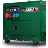
PGI 1200 A1 - Generator PARKSIDE - Free user manual and instructions
Find the device manual for free PGI 1200 A1 PARKSIDE in PDF.
| Product type | Inverter generator |
| Brand | Parkside |
| Model | PGI 1200 A1 |
| Continuous power (S1) | 1000 W |
| Maximum power (S2/5 min) | 1100 W |
| Maximum power (S2/5 s) | 1200 W |
| Rated voltage | 230 V~ |
| Rated current | 4.35 A |
| Frequency | 50 Hz |
| Engine type | 4-stroke, air-cooled |
| Displacement | 54 cm³ |
| Fuel | Unleaded gasoline (not E10) |
| Tank capacity | 4.2 L |
| Engine oil | 0.25 L (15W-40) |
| Weight | 12.8 kg |
| Sound pressure level (L_pA) | 74.39 dB(A) |
| Sound power level (L_WA) | 95 dB(A) |
| Protection rating | IP23M |
| Power class | G1 |
| Quality class | B |
| Spark plug | MS A7RTC (compatible with Bosch UR3AC) |
| Spark plug electrode gap | 0.6 mm |
| Safety functions | Overload protection, automatic oil-shutdown, grounding |
| Included accessories | Oil bottle, handle, screwdriver, spark plug wrench, socket wrench, tool kit, manual |
Frequently Asked Questions - PGI 1200 A1 PARKSIDE
User questions about PGI 1200 A1 PARKSIDE
0 question about this device. Answer the ones you know or ask your own.
Ask a new question about this device
Download the instructions for your Generator in PDF format for free! Find your manual PGI 1200 A1 - PARKSIDE and take your electronic device back in hand. On this page are published all the documents necessary for the use of your device. PGI 1200 A1 by PARKSIDE.
USER MANUAL PGI 1200 A1 PARKSIDE
Operating and Safety Instructions
Translation of Original Operating Manual
NL BE
INVERTER-STROOMGENERATOR
Before reading, unfold the page containing the illustrations and familiarise yourself with all functions of the device.
FR BE
GB / IE / NI Operating and Safety Instructions Page 01
natural_image
Five different types of medical or mechanical tools with black and white outlines, labeled A (no text or symbols on items)3
text_image
8 9 11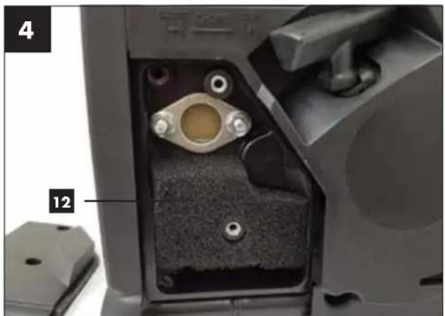
natural_image
Close-up of a mechanical component with labeled parts (4 and 12), showing internal components like a flanged knob and bolted joints (no readable text or symbols beyond labels)5
natural_image
Interior view of a mechanical device showing internal components and labeled parts (13 and 4), no readable text or symbols beyond labels.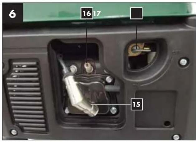
text_image
6 16 17 15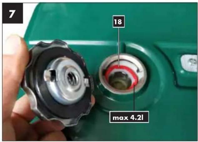
text_image
7 18 max 4.2l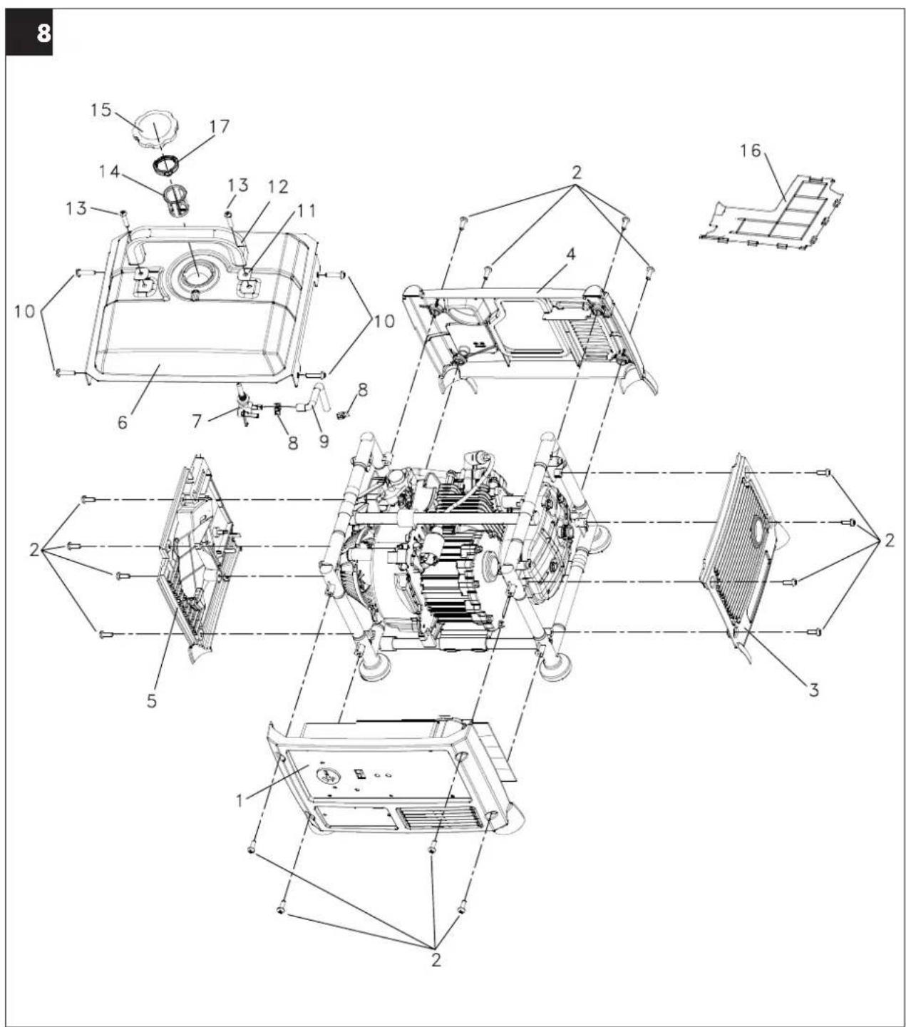
text_image
Technical diagram of a mechanical assembly with numbered components, likely for assembly or maintenance purposes.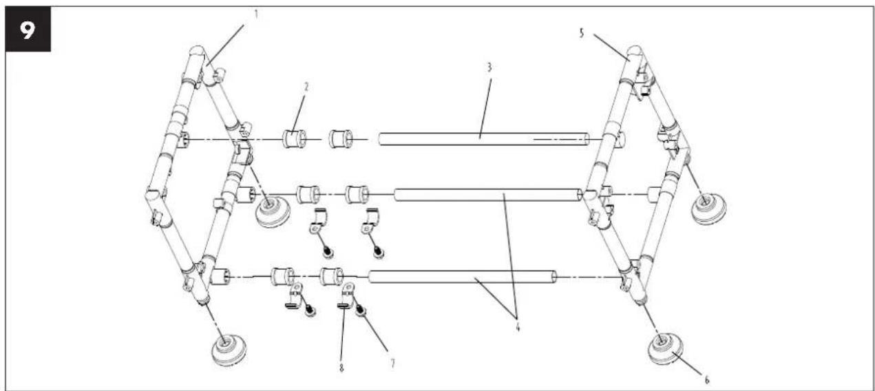
text_image
Technical diagram of a mechanical assembly with numbered components, likely a robotic or mechanical device.
text_image
10 1 2 3 4 5 6 7 8 9 10
text_image
Exploded view diagram of a mechanical assembly with numbered components for identificationTable of contents: Page:
- Introduction......3
- Device description (Fig. 1-12)....3
- Scope of delivery 3
- Intended use....3
- Safety information....4
- Technical data....4
- Before starting the equipment 5
- Operation....5
- Maintenance 6
- Cleaning....6
- Storage 6
- Transport....6
- Disposal and recycling 7
- Troubleshooting....7
- Maintenance schedule 8
- Warranty certificate....9
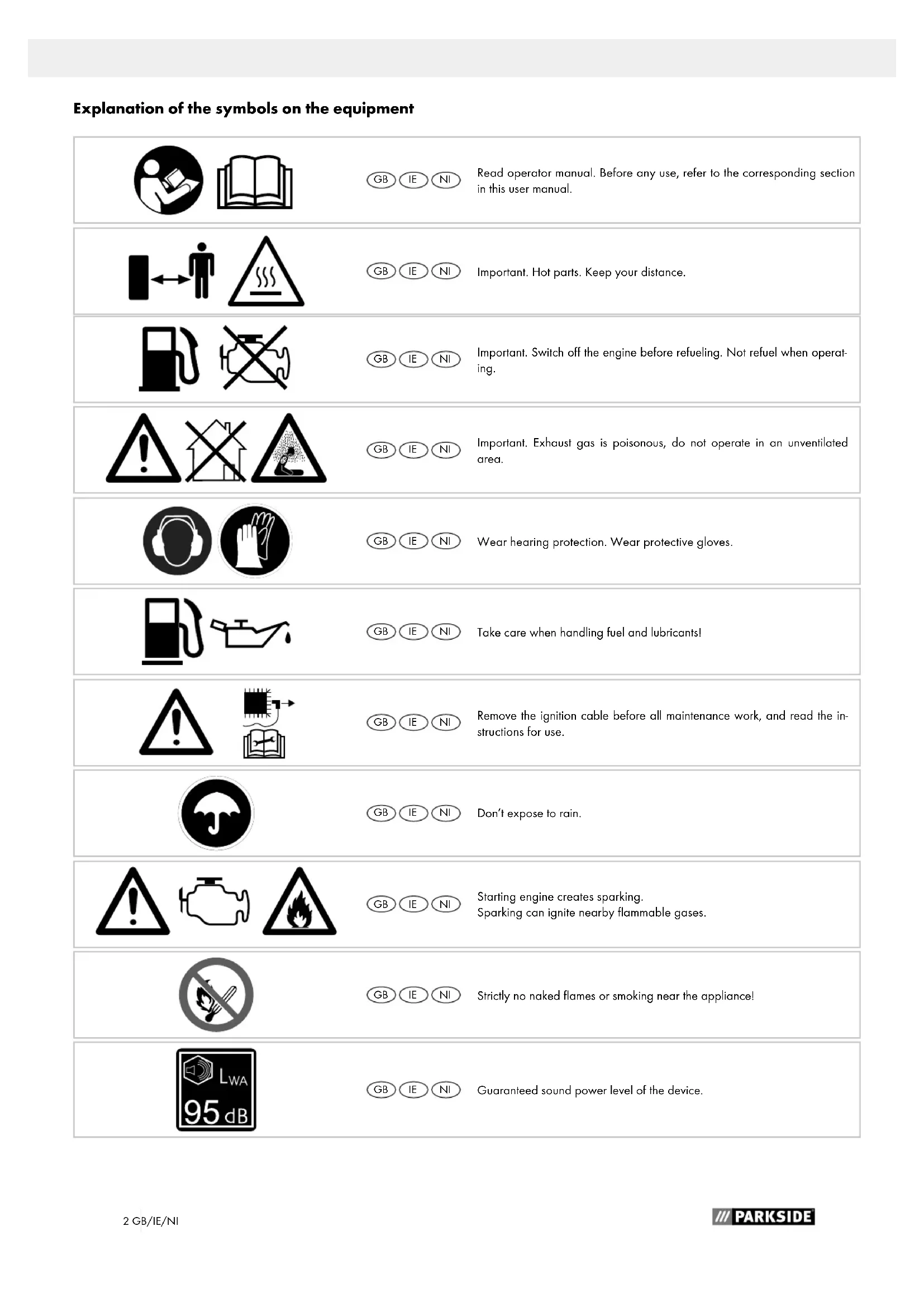
Explanation of the symbols on the equipment


text_image
Safety warning symbol showing a person moving away from a barrier and a triangular hazard sign with steam rising.

text_image
Warning symbols including exclamation mark, house with cross symbol, and person drinking from a pile of water


text_image
Warning symbols including warning triangle, vehicle valve, and flame
GB IE NI Read operator manual. Before any use, refer to the corresponding section in this user manual.
GB IE NI Important. Hot parts. Keep your distance.
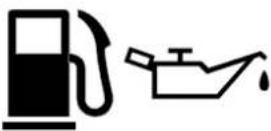
GB IE NI Important. Switch off the engine before refueling. Not refuel when operating.
GB IE NI Important. Exhaust gas is poisonous, do not operate in an unventilated area.
GB IE NI Wear hearing protection. Wear protective gloves.
GB IE NI Take care when handling fuel and lubricants!
Remove the ignition cable before all maintenance work, and read the instructions for use.
GB IE NI Don't expose to rain.
Starting engine creates sparking. Sparking can ignite nearby flammable gases.
GB IE NI Strictly no naked flames or smoking near the appliance!
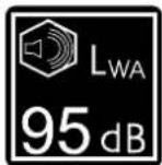
GB IE NI Guaranteed sound power level of the device.
1. Introduction
MANUFACTURER:
scheppach
Günzburger Straße 69
D-89335 Ichenhausen
DEAR CUSTOMER,
we hope your new tool brings you much enjoyment and success.
NOTE:
According to the applicable product liability laws, the manufacturer of the device does not assume liability for damages to the product or damages caused by the product that occurs due to:
- Improper handling,
• Non-compliance of the operating instructions, - Repairs by third parties, not by authorized service technicians,
• Installation and replacement of non-original spare parts,
• Application other than specified,
We recommend:
Read through the complete text in the operating instructions before installing and commissioning the device.
The operating instructions are intended to help the user to become familiar with the machine and take advantage of its application possibilities in accordance with the recommendations. The operating instructions contain important information on how to operate the machine safely, professionally and economically, how to avoid danger, costly repairs, reduce downtimes and how to increase reliability and service life of the machine. In addition to the safety regulations in the operating instructions, you have to meet the applicable regulations that apply for the operation of the machine in your country.
Keep the operating instructions package with the machine at all times and store it in a plastic cover to protect it from dirt and moisture. Read the instruction manual each time before operating the machine and carefully follow its information.
The machine can only be operated by persons who were instructed concerning the operation of the machine and who are informed about the associated dangers. The minimum age requirement must be complied with.
In addition to the safety instructions contained in this operating manual and the specific regulations of your country, the technical rules generally accepted for the operation of machines of the same type must be observed.
We accept no liability for damage or accidents which arise due to non-observance of these instructions and the safety information.
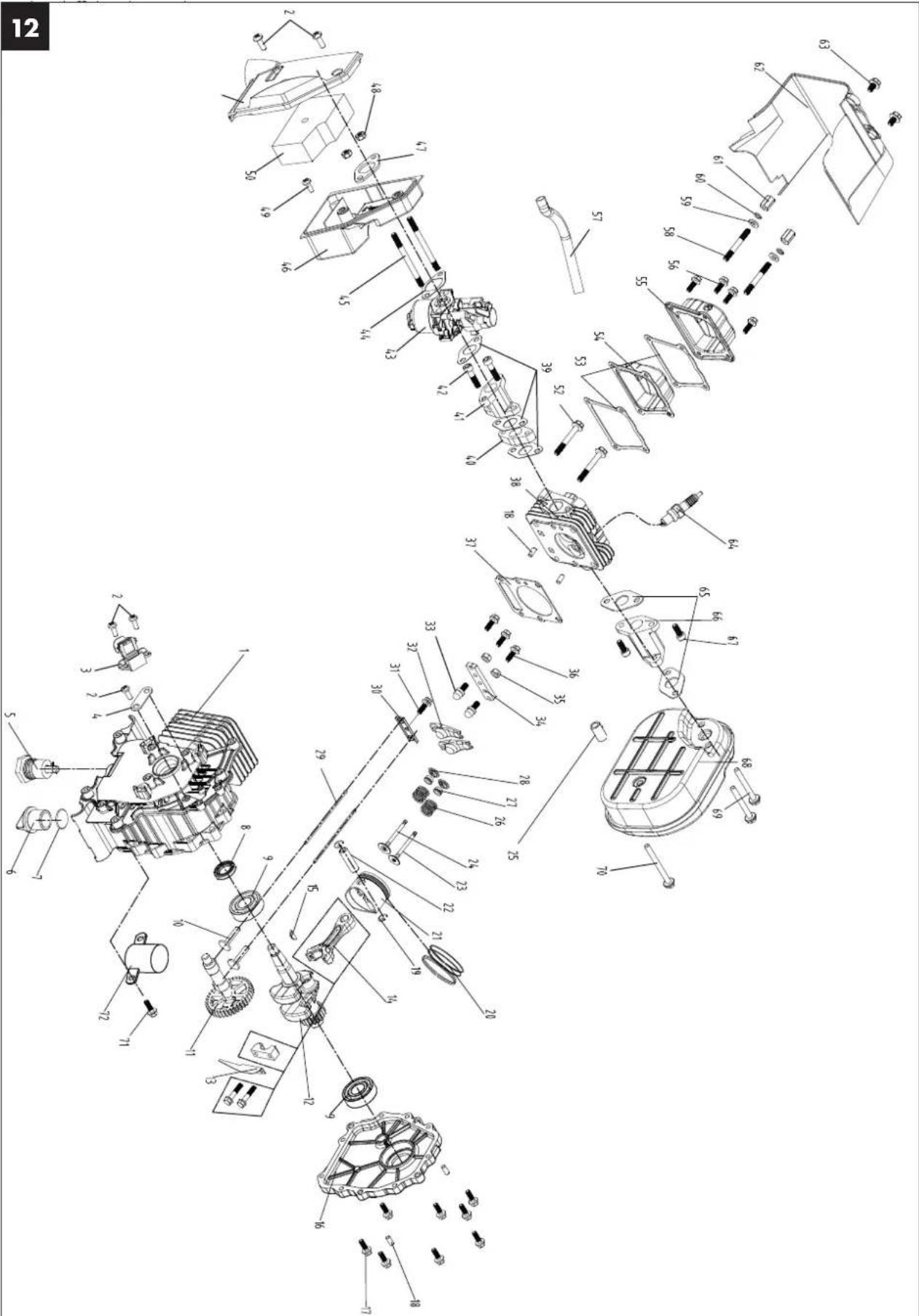
2. Device description (Fig. 1-12)
- Handle
- Fuel tank cap
- Foot
- Operating bulb
- Oil check bulb
- On/off switch
- Earthing screw
- 230 V\~ socket
- Choke lever
- Starter grip
- Air filter lid
- Air filter
- Oil filler plug
- Low oil trip
- Spark plug cap
- Spark plug
- Fuel tap
- Fuel filter
3. Scope of delivery
- Oil filler bottle (A) (1 pcs.)
- Handle (B) (1 pcs.)
- Screwdriver (C) (1 pcs.)
- Spark plug spanner (D) (1 pcs.)
- Socket wrench (E) (1 pcs.)
- Tool bag (F) (1 pcs.)
• Original Operating Manual (1 Stk.)
4. Intended use
The generator is suitable for devices which use a 230 AC voltage source. Please check the suitability for use of house hold devices on the manufacturer information.
The equipment is allowed to be used only for its prescribed purpose. Any other use is deemed to be a case of misuse. The user/operator and not the manufacturer will be liable for any damage or injuries of any kind resulting from such misuse.
An element of the intended use is also the observance of the safety instructions, as well as the assembly instructions and operating information in the operating manual.
Persons who operate and maintain the machine must be familiar with the manual and must be informed about potential dangers.
In addition, the applicable accident prevention regulations must be strictly observed.
Other general occupational health and safety-related rules and regulations must be observed.
The liability of the manufacturer and resulting damages are excluded in the event of modifications of the machine.
Please note that our equipment has not been designed for use in commercial, trade or industrial applications. Our warranty will be voided if the equipment is used in commercial, trade or industrial businesses or for equivalent purposes.
5. Safety information
- No modifications are allowed to be made to the generator
- The speed preset by the manufacturer may not be changed. The generator or connected devices could be damaged.
- Risk of poisoning! Fumes, fuels and lubricants are toxic. Do not breath in the fumes.
- Fire risk! Petrol and petrol fumes are highly flammable and explosive.
- Motor exhaust gases are toxic. The generator must not be operated in unventilated rooms. If the generator is to be operated in well-ventilated rooms, the exhaust gases must be discharged directly outside via an exhaust gas hose. Additional requirements for protection against fire and explosion must also be observed. Even when using an exhaust hose, toxic gas can still escape. Due to the risk of fire, the exhaust hose should never be aimed at combustible material.
- Never use the generator in rooms with highly flammable materials.
- Hot surface! Risk of burning, do not touch the exhaust system and engine unit.
- Do not touch any of the mechanically moving or hot parts. Do not remove any of the protective caps.
- Protective equipment! Use suitable ear protection when near the device.
- Only original parts should be used for maintenance and accessories.
- Repair and maintenance work must only be performed by authorised qualified personnel.
- Protect yourself from electric shocks.
- Never touch the generator with wet hands
- Only use outside with a extension cable which is suitable for that and is appropriately marked (H07RN).
- If extension cables or mobile distribution networks are used, the resistance value must not exceed 1.5 Ω. When using extension cables, the total length of cables for a cross section of 1.5 mm² should not exceed 60 m; for a cross section of 2.5 mm², 100 m should not be exceeded.
- Do not use the generator in the rain or snow.
- Always turn off the engine when transporting or refuelling.
- Fuel is combustible and highly flammable. Do fuel the unit during operation. Do not fuel the unit when someone is smoking or near open flames. Do not spill any fuel.
- Do not refuel or empty near naked lights or flames or flying sparks. Do not smoke!
- Put the generator on a secure and level place. Turning, tipping or changing its position during operation is forbidden.
- Install the generator at least 1 m away from the walls or attached devices.
- Children must be protected by ensuring that they stay a safe distance away from the generator.
-
Some parts of the reciprocating internal combustion motor are hot and may cause burns. The warnings on the generator must be observed.
-
Emission levels are represented in the technical data under the stated values for sound power level ( L_WA ) and sound pressure level ( L_pA ) and are not compulsory definite working levels. Because there is a connection between emission levels and immission levels, this can not reliably used to determine the potentially necessary additional precautions. Influencing factors on the workforce's current immission level includes the properties of the work area, other noise sources, air borne sound, etc. such as e.g. the number of machines and other neighbouring processes and intervals, to which the user is exposed. Also the admissible immission levels can vary from country to country. However, this information gives the user of the machine the opportunity to have a better estimation of the risks and dangers. Occasionally acoustic measurements should be take after installation in order to determine the sound pressure level.
- Warning! Follow the electrical safety regulations that apply to the location where the generators are used.
- Warning! Take into account the requirements and precautionary measures in the event of generators being re-supplied, depending on the protective measures of this device and the applicable directives.
- Generator sets should only be used up to their rated output under the rated ambient conditions. If the application of the generating set is carried out under conditions which do not comply with the reference conditions of ISO 8528-10 (7.1), and if the cooling of the motor or generator is impaired, e.g. as a result of operating in restricted areas, a reduction in performance is required.
ATTENTION: Only use unleaded normal petrol as fuel.
6. Technical data
Generator Inverter
Protection type IP23M
Continuous Power P_nenn (S1) 1000 W
Power P_max (S2/5min) 1100 W
Power P_max (S2/5s) 1200 W
Nominal voltage U_nenn 230 V\~
Rated current I_nenn 4,35 A
Frequency F_nenn 50 Hz
Type drive motor 4 stroke air-cooled
Engine displacement 54 cm ^3
Max. power (motor) 2.1 kW/2.85 PS
| Fuel | Unleaded fuelThis device may not beoperated with E10 petrol |
| Tank capacity | 4.2 l |
| Engine oil | 0.25 l(15W-40) |
| Use at 2/3 engine load approx. 0.88 l/h | |
| Weight 12.8 kg | |
| Sound pressure level L_pA | 74.39 dB (A) |
| Sound power level L_WA | 95 dB(A) |
| Uncertainty K 1.07 dB (A) | |
| Power factor cos φ 1 | |
| Performance class G1 | |
| Quality class B | |
| Spark plug MS A7RTC | |
Operating mode S1 (long use)
The machine can be used continuously with the indicated power.
Operating mode S2 (Short term use)
The machine can be used in the short term with the indicated power.
Acceptable ambient temperature:
-10 to +40 °C
Height: 1000 m above NN
rel. air humidity: 90 % (not condensed)
7. Before starting the equipment
- Open the packaging and remove the device carefully.
- Remove the packaging material as well as the packaging and transport bracing (if available).
- Check that the delivery is complete.
- Check the device and accessory parts for transport damage.
- If possible, store the packaging until the warranty period has expired.
ATTENTION
The device and packaging materials are not toys! Children must not be allowed to play with plastic bags, film and small parts! There is a risk of swallowing and suffocation!
Installation (Fig. 1/2)
To attach the handle (1), remove both Phillips screws M6x35 mm which are inserted. Place the handle (1) in position and screw it tight. Attach all parts before pouring in fuel or oil in order to prevent leaking of liquids.
Electrical safety
Prior to use, the generator and its electrical equipment (including lines and plug connectors) should be checked to ensure that there are no defects.
Never connect the generator to the mains (power point).
Keep the cables as short as possible.
Earthing (Fig. 1)
Earthing is needed to disperse static discharge. Connect a cable from one side of the earthing connector (7) of the generator and from the other side to an external ground.
ATTENTION! When being used for the first time, motor oil (15W-40, approx. 0.25 l) and petrol (unleaded normal petrol) must be put in.
Check the fuel level and the oil, and if necessary top them up. Make sure you have adequate ventilation. Ensure that the spark cable is securely in the spark plug. Unplug any electric device connected to the generator.
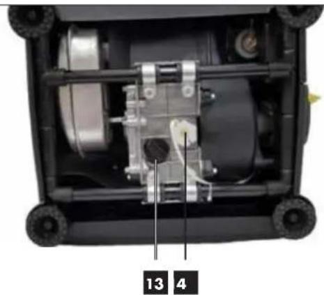
Putting in oil (Fig. 5)
Put the generator with its front side down and unscrew the oil filler plug (13). Pour in 0.25 litres of engine oil (15W-40). Close the oil filler cap (13) and stand the generator upright
Putting in fuel (Fig. 1/7)
Keep away from ignition sources! Always refuel in well-ventilated rooms or outside. Open the fuel tank cap (2) and, using a filler pipe (not included in delivery), pour in a maximum of 4.2 litres of unleaded fuel into the fuel container. Ensure the tank level is not exceeded and no fuel is spilled. Use the fuel filter. Clean up spilled fuel immediately and wait until the fuel fumes have evaporated (fire hazard). Close the fuel tank cap (2).
8. Operation
Start the engine (Fig. 1/3/6)
ATTENTION! When starting with the express start (10) you can injure your hand with the sudden kick back.
Wear protective gloves when starting.
- Open the petrol tap (17) by turning the tap downwards.
- Put the on / off switch (6) to the "on" position. Turn the choke lever (9) to I ↓ (in the left position).
- Start the engine with the express start (10) by sharply pulling the handle. If the engine has not started pull the handle again.
- Push the choke lever (9) back once the engine has started (in the right position).
- Connect the device to the 230 V\~ socket (8).
ATTENTION! This socket can be loaded continuously (S1) with 1000 W and short term (S2) for a maximum of 5 seconds with 1200 W.
Note: Some electric devices (sabre saws, drills etc.) can use more electricity when doing heavy duty tasks.
Storing the engine (Fig. 1/6)
Before putting away, let the generator run without load so that the device can „cool down“.
- Turn the on / off switch to the "OFF" position.
- Close the petrol tap.
Overload protection 230 V\~ socket
NOTE! This generator is fitted with an overload protector. This cuts off the sockets.
Green operating bulb:
Flashes 1 x per interval Speed too low
Flashes 2 x per interval Temperature too high
Flashes 3 x per interval Overload protection
switches on
Flashes 4 x per interval Short circuit
The socket (8) can be used again after the overload protection has been triggered once the engine has been switched off and restarted (See "Turning off engine" and "Starting engine").
ATTENTION! If this happens reduce the amount of electrical output which you are extracting from the generator or remove defective devices which are attached.
ATTENTION! Faulty overload switches should only be replaced with identically constructed overload switches with the same performance data. Please use our customer service department.
ATTENTION! Turn the device off immediately and contact your Service Station:
- With unusual vibrations or noises.
- If the engine seems overloaded or has backfired.
9. Maintenance
Before cleaning and maintenance work, turn off the engine and pull the spark plug connector (15) out of the spark plug (16).
WARNING! Risk of burning! Wait until the machine has cooled down before cleaning or servicing it.
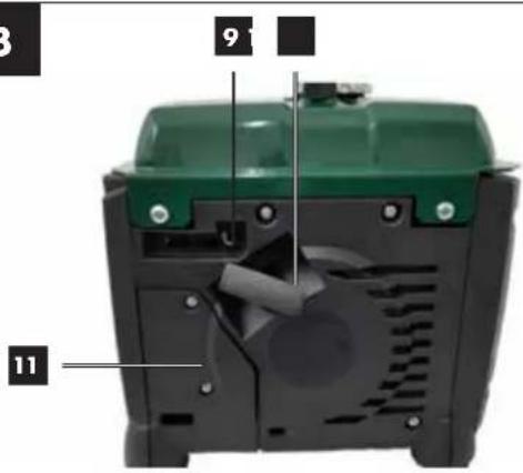
Air filter (Fig. 4)
Also refer to the service information.
Clean the air filter (12) regularly, and if necessary exchange it.
- Open the air filter cover (11) by removing the 2 Phillips head screws M6x16 mm.
- Remove the filter element (12).
- When cleaning the element do not use any strong cleaners or petrol.
- Clean the element by tapping it on a flat surface. If it is very dirty wash with soapy water, rinse with clean water and leave to dry.
- Put it back together in the opposite order.
Spark plug (Fig. 6)
Check the spark plug (16) after the first 20 hours of use for dirt and if necessary clean it with a copper wire brush. Then service the spark plug after every 50 hours of use.
- Remove the spark plug connector (15) with a turning movement.
- Remove the spark plug (16) with the spark plug socket (D) included.
- Put it back together in the opposite order.
Note: alternative spark plugs to
Bosch UR3AC
Petrol filter (Fig. 7)
Note: The petrol filter (18) is a filter bowl located directly under the petrol cap (2), filtering any petrol added.
- Turn the on /o ff switch (6) to the "OFF" position.
- Open the petrol cap (2)
- Turn the on /o ff switch (6) to the "OFF" position. - Open the petrol cap (2)
- Remove the petrol filter (18) and clean in a nonflammable solvent or solvent with a high flash point.
• Reinsert petrol filter (18). - Close the petrol cap (2).
Changing the oil, (Fig. 5)
Changing the oil should take place when the engine is warm.
WARNING! Drain fuel before replacing the oil.
Only use engine oil (15W-40).
- Place the generator on its front side on a suitable surface.
- Open the oil filler cap (13) and drain the warm engine oil into a container by tilting the generator.
- Pour in engine oil (approx. 0.25 litres).
- Close the oil filler cap (13).
- Stand the generator upright again.
Low oil switch off
The low oil switch-off responds, if there is not enough engine oil. The oil check bulb (5) starts to flash when there is insufficient oil in the motor. The check bulb begins to flash when the oil amount has gone below the safe level. The engine will turn off independently after a short time. Restart is possible only after pouring in more engine oil (see Chapter "Replacing the oil").
10. Cleaning
Keep the safeguards, air vents and the engine housing as dust and dirt free as possible. Wipe the device with a clean cloth or blow it with compressed air with low pressure. We recommend that you clean the device after every use. Regularly clean the device with a damp cloth and a little soft soap. Do not use any cleaning products or solvents which could attack the plastic part of the device. Ensure that no water can penetrate the housing.
11. Storage
Preparation for storage
• Empty the petrol tank with a petrol suction pump.
Warning notice: Do not remove fuel in closed rooms, close to fire or whilst smoking. Vapours can cause explosions or fires.
- Start the engine and leave it running until the rest of the petrol has been used up.
- Change the oil after each season. To do this, remove the old oil from the warm engine and refill with new oil.
- Remove the spark plug. Fill about 20 ml of oil into the cylinder using an oil can.
- Slowly pull the express start so that the oil protects the cylinder from the inside.
- Screw the spark plug back in
- Store the device in a well ventilated place or area.
12. Transport
Preparation for transporting
- Empty the petrol tank with a petrol suction pump or alternatively using the petrol tap and a suitable canister.
- Once it is ready for use, leave the engine running until the rest of the petrol has been used up.
• Empty the engine oil from the engine (as described).
- Remove the spark plug connector (15) from the spark plug (16).
- Secure the device with a tension belt to prevent it slipping out of place.
- The generator can be lifted and carried by using the handle (1).
13. Disposal and recycling
The equipment is supplied in packaging to prevent it from being damaged in transit. The raw materials in this packaging can be reused or recycled. The equipment and its accessories are made of various types of material, such as metal and plastic. Defective components must be disposed of as special waste. Ask your dealer or your local council.

The packaging is wholly composed of environment ally-friendly materials that can be disposed of at a local recycling centre.
Contact your local refuse disposal authority for more details of how to dispose of your worn-out electrical devices.
Old devices must not be disposed of with household waste!
This symbol indicates that this product must not be disposed of together with domestic waste in compliance with the Directive (2012/19/EU) pertaining to waste electrical and electronic equipment (WEEE). This product must be disposed of at a designated collection point. This can occur, for example, by handing it in at an authorised collecting point for the recycling of waste electrical and electronic equipment. Improper handling of waste equipment may have negative consequences for the environment and human health due to potentially hazardous substances that are often contained in electrical and electronic equipment. By properly disposing of this product, you are also contributing to the effective use of natural resources. You can obtain information on collection points for waste equipment from your municipal administration, public waste disposal authority, an authorised body for the disposal of waste electrical and electronic equipment or your waste disposal company.
Environmental protection
Take any contaminated maintenance material and operating materials to a collection point designated for this purpose.
When disposing of residual fluids (oils and fuel), observe the corresponding environmental regulations. We recommend taking all remaining operating materials to your local collection point in a suitable sealed container. Do not pour the remaining operating materials into waste or on the ground.
14. Troubleshooting
| Fault Possible cause Remedy | ||
| Engine does not start | Automatic oil cut-out has not responded | Check oil level, top up engine oil |
| Spark plug fouled Clean or replace spark plug | ||
| No fuel Refuel / have the petrol cock checked | ||
| Generator has too little or no voltage | Electronic defective | Contact your dealer |
| Over-current circuit-breaker has triggered Actuate | the circuit-breaker and reduce the consumers | |
| Air filter dirty Clean or replace the filter |
15. Maintenance schedule
Please adhere to the following maintenance periods in order to ensure a failure-free operation.
IMPORTANT! The equipment must be filled with engine oil and fuel before it is started.
| Before each use After | an operating period of 20 hours | After an operating period of 50 hours | After an operating period of 100 hours | After an operating period of 300 hours | |
| Checking the engine oil | X | ||||
| Changing the engine oil For the first time, then | every 50 hours | X | |||
| Checking the air filter | X | Change the filter insert if necessary | |||
| Cleaning the air filter | X | ||||
| Cleaning the petrol filter | X | ||||
| Visual inspection of the equipment | X | ||||
| Cleaning the spark plug Distance: 0.6 | mm, replace if necessary | ||||
| Checking andreadjusting the throttle vale on the carburetor | X* | ||||
| Cleaning the cylinder head | X* | ||||
| Set the valve play | X* | ||||
| Important: The positions marked with "x*" should only be carried out by an authorized dealer. | |||||
Service information
Please note that the following parts of this product are subject to normal or natural wear and that the following parts are therefore also required for use as consumables.
Wear parts*: Spark plug
* Not necessarily included in the scope of delivery!
16. Warranty certificate
Dear Customer,
All of our products undergo strict quality checks to ensure that they reach you in perfect condition. In the unlikely event that your device develops a fault, please contact our service department at the address shown on this guarantee card. Of course, if you would prefer to call us then we are also happy to offer our assistance under the service number printed below. Please note the following terms under which guarantee claims can be made:
- These guarantee terms cover additional guarantee rights and do not affect your statutory warranty rights. We do not charge you for this guarantee.
- Our guarantee only covers problems caused by material or manufacturing defects, and it is restricted to the rectification of these defects or replacement of the device. Please note that our devices have not been designed for use in commercial, trade or industrial applications. Consequently, the guarantee is invalidated if the equipment is used in commercial, trade or industrial applications or for other equivalent activities. The following are also excluded from our guarantee: compensation for transport damage, damage caused by failure to comply with the installation/assembly instructions or damage caused by unprofessional installation, failure to comply with the operating instructions (e.g. connection to the wrong mains voltage or current type), misuse or inappropriate use (such as overloading of the device or use of non-approved tools or accessories), failure to comply with the maintenance and safety regulations, ingress of foreign bodies into the device (e.g. sand, stones or dust), effects of force or external influences (e.g. damage caused by the device being dropped) and normal wear resulting from proper operation of the device.
The guarantee is rendered null and void if any attempt is made to tamper with the device.
- The guarantee is valid for a period of 3 years starting from the purchase date of the device. Guarantee claims should be submitted before the end of the guarantee period within two weeks of the defect being noticed. No guarantee claims will be accepted after the end of the guarantee period. The original guarantee period remains applicable to the device even if repairs are carried out or parts are replaced. In such cases, the work performed or parts fitted will not result in an extension of the guarantee period, and no new guarantee will become active for the work performed or parts fitted. This also applies when an on-site service is used.
- In order to assert your guarantee claim, please send your defective device postage-free to the address shown below. Please enclose either the original or a copy of your sales receipt or another dated proof of purchase. Please keep your sales receipt in a safe place, as it is your proof of purchase. It would help us if you could describe the nature of the problem in as much detail as possible. If the defect is covered by our guarantee then your device will either be repaired immediately and returned to you, or we will send you a new device.
Of course, we are also happy offer a chargeable repair service for any defects which are not covered by the scope of this guarantee or for units which are no longer covered. To take advantage of this service, please send the device to our service address.
Service-Hotline (GB/IE/NI):
+800 4003 4003
(0,00 EUR/Min.)
Service-Email (GB):
service.GB@scheppach.com
Service-Email (IE/NI):
service.IE@scheppach.com
Service Address (GB/IE/NI):
Doyles Wholesale
Dublind Road
Castlecomer, Co. Kilkenny R95AP6F

text_image
PDF ONLINE www.lidl-service.comAt www.lidl-service.com you can download this and many more manuals, product videos plus installation software.
The QR code takes you directly to the Lidl service page (www.lidl-service.com) and you can open your operating manual by entering the article number (IAN) 311314.
Table des matières: Page:
text_image
Safety warning symbol showing a person moving away from a barrier and a triangular hazard symbol with steam.

text_image
Warning symbols including exclamation mark, house with cross symbol, and person drinking from a pile of water


natural_image
Two black circular icons with white umbrella symbols, no text or numbers present
text_image
Warning symbols including warning triangle, vehicle icon, and flame symbol

FR BE
Günzburger Straße 69
D-89335 Ichenhausen
CHERS CLIENTS,
Service-hotline (BE):
+800 4003 4003
(0,00 €/Min.)
Email du service (FR):
service.FR@scheppach.com
E-mailadres (BE):
service.BE@scheppach.com
Günzburger Straße 69
D-89335 Ichenhausen
BESTE KLANT,
Benzinefilter (afb. 7)
service.NL@scheppach.com
E-mailadres / Email du service (BE):
service.BE@scheppach.com
Serviceadres / Adresse du service (NL/BE):
text_image
Safety warning symbol showing a person moving away from a barrier and a triangular hazard sign with steam rising.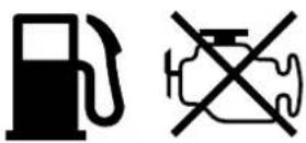

text_image
Warning symbols including exclamation mark, house with cross symbol, and person sitting on phone


text_image
Warning symbols including warning triangle, vehicle icon, and flame symbol

DE AT CH
Günzburger Straße 69
D-89335 Ichenhausen
VEREHRTER KUNDE,
service.AT@scheppach.com
service.CH@scheppach.com
Service Adresse (DE):
Service Adresse (AT):
Gausch Hubert
CE - Declaration of Conformity
Translation of the original EC declaration of conformity
CE
Standard references:
DIN EN ISO 8528-13; EN 55012/A1; EN 6100-6-1; EN 62321; EN 3744; ISO 8528-10
This declaration of conformity is issued under the sole responsibility of the manufacturer.
The object of the declaration described above fulfils the regulations of the directive 2011/65/EU of the European Parliament and Council from 8th June 2011, on the restriction of the use of certain hazardous substances in electrical and electronic equipment.
Subject to change without notice
Documents registar: Andreas Pecher
Günzburger Str. 69, D-89335 Ichenhausen
text_image
Exploded view diagram of a mechanical assembly with numbered parts for identificationCE