WL1218V - Wood lathe Vevor - Free user manual and instructions
Find the device manual for free WL1218V Vevor in PDF.

| Brand | Vevor |
| Model | WL1218V |
| Product Type | Wood Lathe |
| Supply Voltage | 220 V / 50 Hz (110 V / 60 Hz) |
| Motor Power | 750 W |
| Motor Speed | 0-5000 rpm |
| Spindle Speed | 0-3800 rpm ±10% |
| Maximum Swing Diameter | 304 mm (12 in) |
| Distance Between Centers | 465 mm (18 in) |
| Spindle Taper | MT2 |
| Spindle Thread | 1"-8 |
| Tailstock Quill Travel | 50 mm |
| Tailstock Taper | MT2 |
| Digital Speed Display | Yes |
| Speed Variation | Variable with electronic control |
| Rotation Direction | Reversible (forward/reverse) |
| Tool Rests Included | 2 (one mounted, one as accessory) |
| Included Accessories | Spur center, live center, faceplate, knock-out rod, hex keys S2.5/S3/S5, wrench |
| Power Supply | Mains with mandatory grounding |
Frequently Asked Questions - WL1218V Vevor
User questions about WL1218V Vevor
0 question about this device. Answer the ones you know or ask your own.
Ask a new question about this device
Download the instructions for your Wood lathe in PDF format for free! Find your manual WL1218V - Vevor and take your electronic device back in hand. On this page are published all the documents necessary for the use of your device. WL1218V by Vevor.
USER MANUAL WL1218V Vevor
Affordable. Reliable. Home Improvement.
WOOD LATHE
MODEL:WL1218V
VEVOR
Affordable. Reliable. Home Improvement.
WOOD LATHE
MODEL:WL1218V

natural_image
Line drawing of a mechanical lathe machine with dual levers and control panel (no text or symbols)This is the original instruction, please read all manual instructions carefully be operating. VEVOR reserves a clear interpretation of our user manual. The appearance of the product shall be subject to the product you received. Please forgive us that we won't inform you again if there are any technology or soft updates on our product.
 | Warning-To reduce the risk of injury, user must read instructions m carefully. |
 | This device complies with Part 15 of the FCC Rules. Operation is the following two conditions:(1)This device may not cause harmful interference, and (2)this device must accept any interference received including interference that may cause undesired operation. |
 | This product is subject to the provision of European Directive 2012/ The symbol showing a wheelie bin crossed through indicates that the product requires separate refuse collection in the European Union. T applies to the product and all accessories marked with this symbol. marked as such may not be discarded with normal domestic waste be taken to a collection point for recycling electrical and electronic |
MATTERS NEEDING ATTENTION
The information contained in this handbook is intended as a guide to the operation of these machines and does not form part of any contract. The data it contains has obtained from the machine manufacturer and from other sources. We strive to enter the accuracy of this information and try to verify each item and each data, but cannot guarantee the full accuracy of the information, which means that the equipment supply may differ in detail from the description of the instructions. Furthermore, development of the machine may mean that the equipment supplied may differ in from the descriptions herein. The responsibility therefore lies with the user to satisfy himself that the equipment or process described is suitable for the purpose intended
SAFETY INSTRUCTIONS FOR MACHINERY
WARNING: Read all safety warnings, instructions, illustrations and specifications provided with this machine. Failure to follow all instructions listed below may result in electric shock, fire and/or serious injury.
Save all warnings and instructions for future reference.
-
Owner's manual. Read and understand this owner's manual before using machine.
-
Trained operators only. Untrained operators have a higher risk of being hurt or killed. Only allow trained/supervised people to use this machine. When machines is not being used, dis-connect power, remove switch keys, or lock-out machines to prevent unauthorized use—especially around children. Make your workshop proof!
-
Dangerous environments. Do not use machinery in areas that are wet, cluttered have poor lighting. Operating machinery in these areas greatly increases the of accidents and injury.
-
Mental alertness required. Full mental alertness is required for safe operation of machinery. Never operate under the influence of drugs or alcohol, when tired when distracted.
-
Electrical equipment injury risks. You can be shocked, burned, or killed by to live electrical components or improperly grounded machinery. To reduce this only allow qualified service personnel to do electrical installation or repair work and always disconnect power before accessing or exposing electrical equipment
-
Disconnect power first. Always disconnect machine from power supply before making adjustments, changing tooling, or servicing machine. This prevents an injury risk from unintended startup or contact with live electrical components.
-
Eye protection. Always wear ANSI-approved safety glasses or a face shield with operating or observing machinery to reduce the risk of eye injury or blindness flying particles. Everyday eyeglasses are not approved safety glasses.
-
Wearing proper apparel. Do not wear clothing, apparel or jewelry that can be entangled in moving parts. Always tie back or cover long hair. Wear non-slip footwear to reduce risk of slipping and losing control or accidentally contacting cutting tool or moving parts.
-
Hazardous dust. Dust created by machinery operations may cause cancer, birth defects, or long-term respiratory damage. Be aware of dust hazards associated with each work piece material. Always wear a niosh-approved respirator to re your risk.
-
Hearing protection. Always wear hearing protection when operating or observing loud machinery. Extended exposure to this noise without hearing protection can cause permanent hearing loss.
-
Remove adjusting tools. Tools left on machinery can become dangerous projectiles upon startup. Never leave chuck keys, wrenches, or any other too on machine. Always verify removal before starting!
-
Use correct tool for the job. Only use this tool for its intended purpose—do force it or an attachment to do a job for which it was not designed. Never unapproved modifications—modifying tool or using it differently than intended may result in malfunction or mechanical failure that can lead to personal injury death!
-
Awkward positions. Keep proper footing and balance at all times when opera machine. Do not overreach! Avoid awkward hand positions that make work p control difficult or increase the risk of accidental injury.
-
Children & bystanders. Keep children and bystanders at a safe distance from work area. Stop using machine if they become a distraction.
-
Forcing machinery. Do not force machine. It will do the job safer and better rate for which it was designed.
-
Never stand on machine. Serious injury may occur if machine is tipped or if the cutting tool is unintentionally contacted.
-
Stable machine. Unexpected movement during operation greatly increases risk injury or loss of control. Before starting, verify machine is stable and mobile (if used) is locked.
-
Use recommended accessories. Consult this owner's manual or the manufacture for recommended accessories. Using improper accessories will increase the risk of serious injury.
-
Unattended operation. To reduce the risk of accidental injury, turn machine off and ensure all moving parts completely stop before walking away. Never le machine running while unattended.
-
Maintain with care. Follow all maintenance instructions and lubrication schedule to keep machine in good working condition. A machine that is improperly maintained could malfunction, leading to serious personal injury or death.
-
Damaged parts. Regularly inspect machine for damaged, loose, or misadjusted parts—or any condition that could affect safe operation. Immediately repair/replace before operating machine. For your own safety, do not operate machine with damaged parts!
-
Maintain power cords. When disconnecting cord-connected machines from
power, grab and pull the plug—not the cord. Pulling the cord may damage wires inside. Do not handle cord/plug with wet hands. Avoid cord damage b keeping it away from heated surfaces, high traffic areas, harsh chemicals, ar wet/damp locations.
- Experiencing difficulties. If at any time you experience difficulties performing the intended operation, stop using the machine!
Remaining risk factors

WARNING
It is important to ensure that each machine has remaining in the execution of all work (even the simplest) greatest at is required. A safe working depends on you!
Even if the machine is used as required it is still impossible to eliminate certain risk factors totally. The following hazards may arise in connection with the machine construction and design:
-
Keeping guards in place. Make sure all guards are in place and that the latl sits on a flat, stable surface.
-
Eye/face protection. Airborne wood dust and debris can be hazardous to the eyes/face and may cause allergies or long-term respiratory health problems. Always wear eye protection or a face shield when operating the lathe.
-
Respiratory protection. Always wear a respirator when using this machine. Wood dust may cause allergies or long-term respiratory health problems.
-
Mounting work piece. Before starting, be certain the work piece has been properly embedded on the head stock and tail stock centers and that there adequate clearance for the full rotation.
-
Adjusting tool rest. Adjust tool rest to provide proper support for the turning tool you will be using. Test tool rest clearance by rotating work piece by h before turning lathe on.
-
Turning speed. Select the correct turning speed for your work, and allow the lathe to gain full speed before using.
-
Using sharp chisels. Keep lathe chisels properly sharpened and held firmly in position when turning.
-
Operating damaged lathe. Never operate the lathe with damaged or worn part
- Work piece condition. Always inspect the condition of your work piece. do not turn pieces with knots, splits, and other potentially dangerous conditions. Make sure joints of glued-up pieces have high quality bonds and won't fly apart operation.
- Adjustments/maintenance. Make sure your wood lathe is turned off, disconnected from its power source, and all moving parts have come to a complete stop before starting any inspection, adjustment, or maintenance procedure.
- Stopping lathe. Do not stop the lathe by using your hand against the work piece. Allow the lathe to stop on its own.
- Avoiding entanglement. Keep long hair and loose clothing articles such as sleeves, belts, and jewelry items away from the lathe spindle.
- Face plate turning. When face plate turning, make sure the face plate is securely attached to the work piece and it is properly attached to the spind. When face plate turning, use lathe chisels on the downward spinning side of work piece only.
- SANDING/POLISHING. Remove the tool rest when performing sanding or polishing operations on the rotating spindle.
- Material Removal Rate. Attempting to remove too much material at once may cause work piece to fly out of the lathe.
- Kickback is a sudden reaction. This causes the ejection of the tool to the operation of the operator.
- These risk factors can be minimized through obeying all security and operating instructions, proper machine maintenance, proficient and appropriate operation by persons with technical knowledge and experience.
- No list of safety guidelines can be complete. Every shop environment is difficult. Always consider safety first, as it applies to your individual working condition. Use this and other machinery with caution and respect. Failure to do so coresult in serious personal injury, damage to equipment, or poor work results.
● The machine shall not be operated outdoors or in wet or damp areas.
- The machine shall not be operated in areas exposed to increased fire or explosion hazard.
- The operation of the machine outside the stated technical limits described in manual is forbidden.
- Operation of the machine function without emergency stop button or impeller with open doors is prohibited.
● The use of the machine not according with the required dimensions is forbid - The use of the machine not being suitable for the use of the machine and being certified is forbidden.
- Any manipulation of the machine and parts is forbidden.
- The use of the machine for any purposes other than described in this user-is forbidden.
- The unattended operation on the machine during the working process is forbidden!
- It is not allowed to leave the immediate work area during the work is being performed.
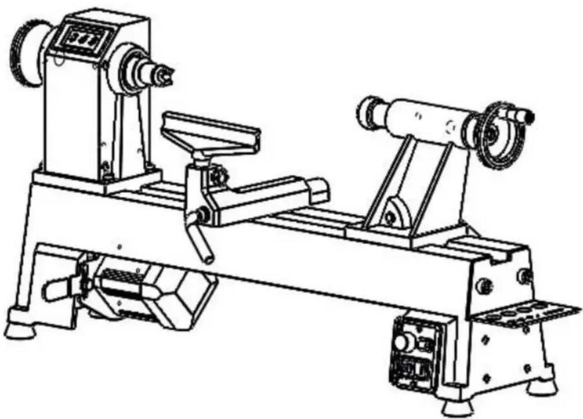
MACHINE DESCRIPTION
- The Wood Lathe is designed to turn wood stock so the operator can remove material with a chisel.
- The variable speed control allows for spindle speed adjustment from 0–3800 RPM and the digital readout provides a precise reading of the current spindle speed.
- This manual contains instructions on installation, safety precautions, general operating procedures, maintenance instructions and parts breakdown. Your machine has been designed and constructed to provide consistent, long-term operation if used in accordance with the instructions as set forth in this doc
- This manual is not intended to be an exhaustive guide to lathe operational methods, use of after-market accessories, choice of stock, and such. Addition knowledge may be obtained from experienced users or trade articles. Whatev accepted methods are used, always make personal safety a priority.
- Retain this manual for future reference. If the machine transfers ownership, the manual should accompany it.
TECHNICAL PARAMETER
| Model | WL1218V | |
| Voltage | 220 V / 50 Hz | 110 V / 60 Hz |
| Motor Power | 750 W | |
| Motor Speed | 0-5000 RPM | |
| Spindle Speed | 0-3800 RPM ±10% | |
| Max. Turning Diameter | 12"(304 mm) | |
| Spindle Taper | MT2 | |
| Spindle Thread | 1"-8 | |
| Distance Between Center | 18"(465 mm) | |
| Tailstock Spindle Travel | 50 mm | |
| Taper in Tailstock Spindle | MT2 | |
SETUP AND ASSEMBLY
The Lathe must be disconnected from power during assembly.
5.1 Delivery contents
Please check the product contents immediately after receipt for any eventual transport damage or missing parts. Claims from transport damage or missing part must be placed immediately after initial machine receipt and unpacking before put the machine into operation. Please understand that later claims cannot be accepted anymore.
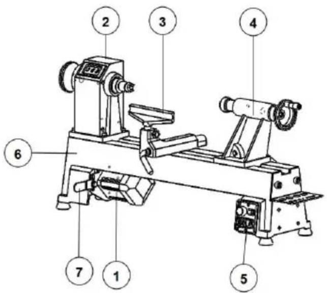
| PART NO. | DESCRIPTION | QTY |
| 1 | Motor | 1 |
| 2 | Head stock | 1 |
| 3 | Tool rest (The other one is an accessory) | 2 |
| 4 | Tail stock | 1 |
| 5 | Switch | 1 |
| 6 | Bed | 1 |
| 7 | Motor fixing board | 1 |
Standard accessories
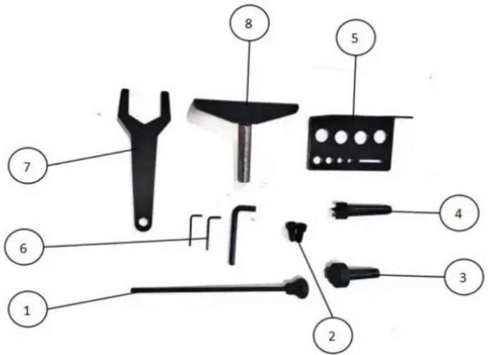
| PART NO. | DESCRIPTION | QTY |
| 1 | Rod injection | 1 |
| 2 | Hexagon socket button head screwsM10×25 | 2 |
| 3 | Living center | 1 |
| 4 | Spur center | 1 |
| 5 | Tool holder | 1 |
| 6 | Hex wrench S2.5、S3、S5 | 3 |
| 7 | Wrench | 1 |
| 8 | Tool rest | 1 |
5.2 Unpacking and cleanup
- Remove the woodworking lathe from the box
- Check all the accessories of the machine tool according to the packing list.
-
Choose a location for the lathe that is dray, has good lighting and has enough room to be able to service the lathe on all four sides.
-
To avoid twisting the bed, the lathe's location must be absolutely flat and lev
-
Clean all rust protected surfaces using a mild commercial solvent, kerosene or diesel fuel. Do not use paint thinner, gasoline or lacquer thinner. These will damage painted surfaces. Cover all cleaned surfaces with a light film of 20V machine oil.
5.3 Preparatory activities
1. Workplace requirements
● The workplace has to fulfill the requirements.
● The ground has to be even, in level and hard.
- The chosen workplace must have access to a suitable electric supply net has complies with the machines requirements.
2. Preparation of the surface
- Uncoated metal machine parts have been insulated with a greasy layer to in corrosion.
- This layer has to be removed. You can use standard solvents that do not the machine surface.
5.4 Assembly
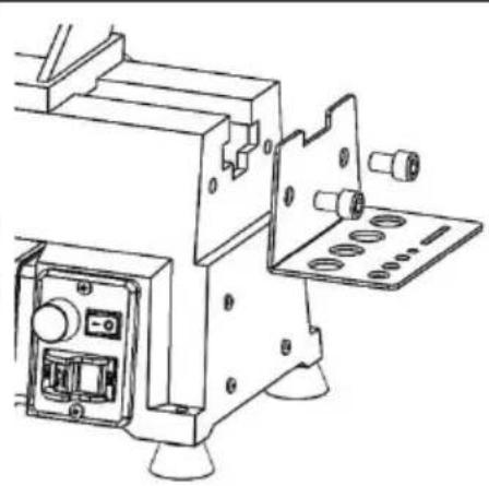
Tool shelf:
Attach the tool shelf with two Hexagon s button head screwsM10×25 to the lathe b
natural_image
Technical line drawing of a mechanical device with mounting flanges and control panel (no text or symbols)POWER SUPPLY
The connection of the machine to the electric power supply and the following ch have to be carried out by a respectively trained electrician only.
- The electronic connection of the machine is designated for operation with a grounded power socket!
● The mains supply must be secured with 10A: - If the connector plug doesn't fit or if it is defective, only qualified electricians modify or renew it!
● The grounding wire should be held in green-yellow.
● A damaged cable has to be exchanged immediately! - Check, whether the feeding voltage and the Hz comply to the required value the machine. A deviation of feeding voltage of ± 5% is allowed.
● After connecting, check the right running direction! - Make sure that a possible extension cord is in good condition and suitable transmission of power. An undersized cord reduces the transmission of power and heats up.
6.1 Grounding instructions
- This tool must be grounded. In the event of a malfunction or breakdown, grounding provides a path of least resistance for electric current to reduce the level of electric shock. This tool is equipped with an electric cord having an equipment-grounding conductor and a grounding plug. The plug must be inserted into an appropriate outlet that is properly installed and grounded in accordance with all local codes and ordinances.
- Improper connection of the equipment-grounding conductor can result in a risk electric shock. Check with a qualified electrician or service person if you are doubt as to whether the outlet is properly grounded. Do not modify the plug provided with the tool – if it will not fit the outlet, have a proper outlet ins qualified electrician.
- The conductor with insulation having an outer surface that is green with or yellow stripes is the equipment-grounding conductor. If repair or replacement, the electric cord or plug is necessary, do not connect the equipment ground conductor to a live terminal. Use only 3-wire extension cords that have 3-pro grounding plugs and 3-pole receptacles that accept the tool's plug.
● Repair or replace damaged or worn cord immediately.
6.2 Extension cords
The use of extension cords is discouraged; try to position equipment within the power source. If an extension cord becomes necessary, be sure it is heat enough to carry the current your product will draw. An undersized cord will cause a drop in line voltage resulting in loss of power and overheating.
ADJUSTMENTS
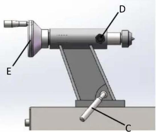
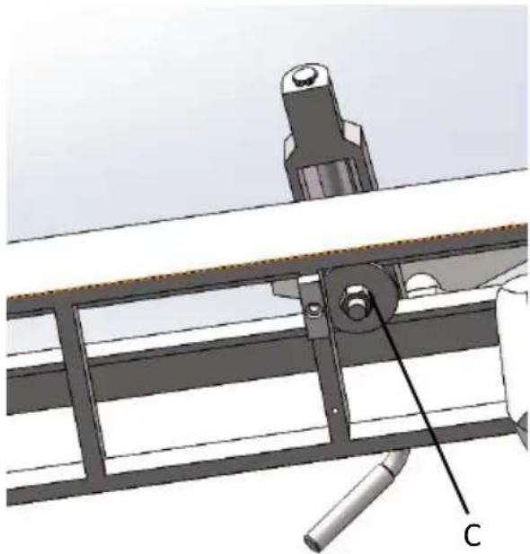
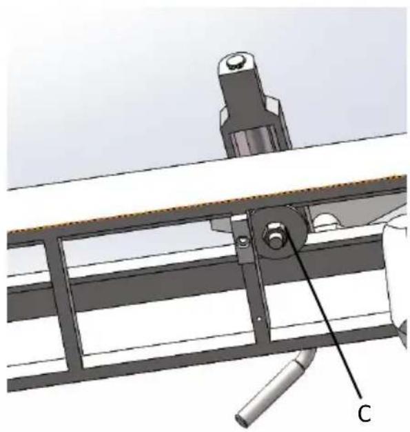
Tailstock movement
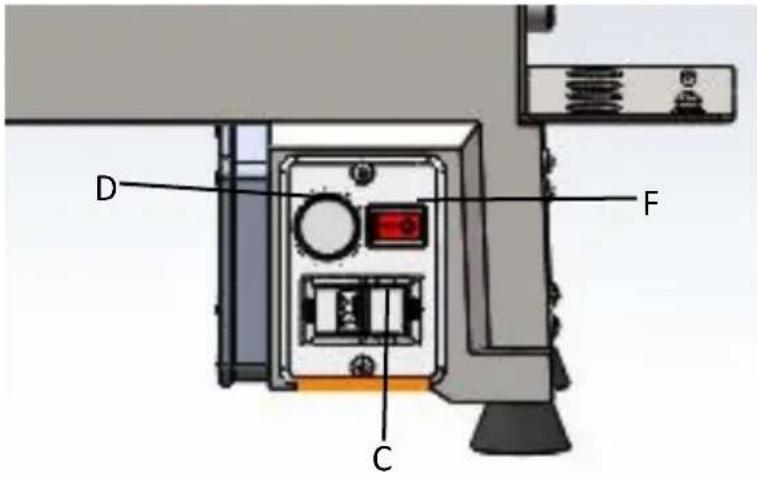
To slide tailstock, push locking handle (C) down toward bed. Push handle up to loc tailstock in position.
To move quill, loosen handle (D) and rot handwheel (E).
Make sure tailstock is locked to bed (C) and quill is tightened (D) b turning a spindle on the lathe
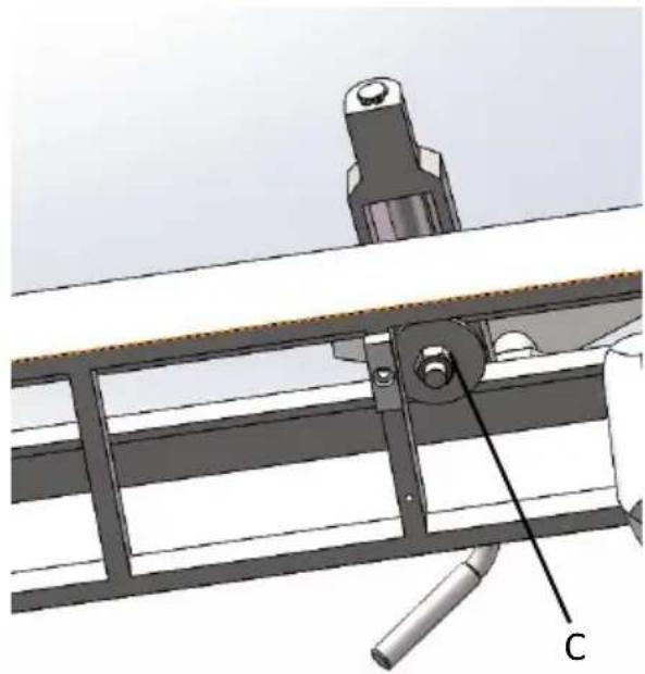
Cam tightness
The clamping mechanisms of tailstock and tool rest base are pre-set by the manufa and should not require adjustment.
If one of them does not tighten properly against the bed when the locking handle tightened, adjust it as follows.
- Remove stud from end of lathe bed, slide tailstock off.
- Turn tailstock on its side, and tighten nut (F) to increase cam pressure, or loos the nut to relieve cam pressure.
- Mount tailstock on bed and lock it to adjustment. Repeat as needed.
- Reinstall stud.
natural_image
Technical diagram of a mechanical assembly with labeled component C (no readable text or symbols)| Tool restTool rest is provided with your lathe. It is designed to allow adjustment for height, position on the bed, and angle to the wLoosen locking handle on tool rest base slide base forward or back, and to angle the bed. Tighten locking handle firmly be operating lathe.Loosen handle (H) to raise or lower tool and angle it to the work. Tighten handle operating lathe. | 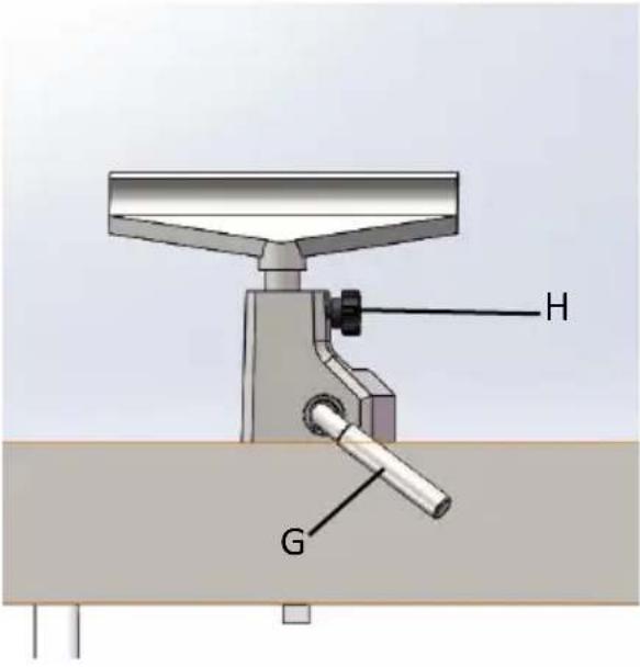 |
| Spur center: Installing/removingThe spur center (K)is installed into the head spindle. The center should first be mounted your workpiece, and then installed into the spindle.1. Disconnect lathe from power source.2. Clean tapered end of center, and inside headstock spindle, then push center into headstock spindle.3. To remove a center, first remove workpie from lathe. Insert knockout rod (J)through ho handwheel and tap the end of spur center. |  |
| Live center: Installing/removingLive centers are installed into the tailstock 01. Disconnect lathe from power source.2. Clean tapered end of center and inside tailstock quill, then push center into quill.3. Always tighten quill locking handle, once live center has been properly positioned in workpiece. Make sure keyway in quill is align with locking handle. | 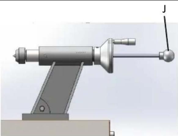 |
| 4.To remove a live center, first remove work from lathe.Insert knockout rod (J)through hole handwheel and tap the end of live center. | |
| Face plate: Installing/removing1. Disconnect lathe from power source.2. Mount face plate to your work piece.3. Install knockout rod onto the hole of the headstock spindle.4. Install face plate onto threads of headsto spindle and rotate clockwise as far as it with 5. Tighten both set screws in face plate. F plate is now ready for turning.6.To remove face plate, engage knockout ro Loosen both set screws in face plate, and face plate counterclockwise with face plate wrench to loosen. | 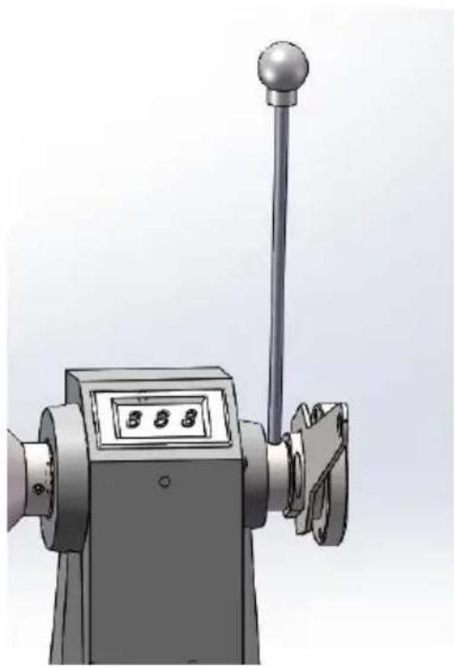 |
OPERATING CONTROLS
Speed control knob (D): Clockwise to increase, counterclockwise to decrease. Spe is displayed as RPM (revolutions per minute) on digital readout.
Forward/Reverse (F): Control the steering of the spindle.
On/off switch (C): Pull to start lathe, push to stop.
OPERATION
The information which follows is general in nature and not intended to be a cor course in woodturning. Nothing can replace the knowledge gained by talking with experienced wood turners or consulting books or trade magazines. Above all, sim trial and error will aid in developing proficiency in the craft.
9.1 Inspection
Device to be operated in a perfect state only. Inspect the device visually every to be used. Check in particular the safety equipment, electrical controls, electric c and screwed connection for damage and if tightened properly. Replace any damage parts before operating the device.
● Level your machine; use the leveling feet to help reduce vibration.
- Check bearings; adjust only if endplay exists.
- Check belt; it should be snug but not overly tight.
- Bed ways; keep clean, use steel wool to remove any rust spots, and apply wax to prevent buildup of rust and finishes.
● Tool rest; use a mill file to remove nicks and dings.
- Spindle tapers; should be clean and free of dust and chips for proper seat tapers.
● Tailstock; clean and lubricate quill and locking device.
● Lighting; proper lighting is essential to eliminate shadows and reduce eye str
9.2 Turning Tools
If possible, select only good-quality, high-speed steel turning tools. High-speed steel tools hold an edge and last longer than ordinary carbon steel. As one be proficient in turning, a variety of specialty tools for specific applications can be acquired. The following tools provide the basics for most woodturning projects.
Gouges—Mainly used for rough cutting, detail cutting, and cove profiles. The ro gouge is a hollow, double-ground tool v round nose, and the detail gouge is a hollow, double-ground tool with either a round or pointed nose.
natural_image
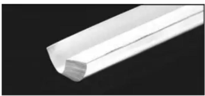
Close-up of a white plastic strip against a black background (no text or symbols visible)| Skew Chisel—A very versatile tool that be used for planning, squaring, V-cutting beading, and parting off. The skew chis flat, double-ground with one side higher than the other (usually at an angle of 20°–40°). |  |
| Scrapers—Typically used where access to other tools is limited, such as hollowing operations. This is a flat, double-ground that comes in a variety of profiles (rou nose, spear point, square nose, etc.) to match many different contours. | 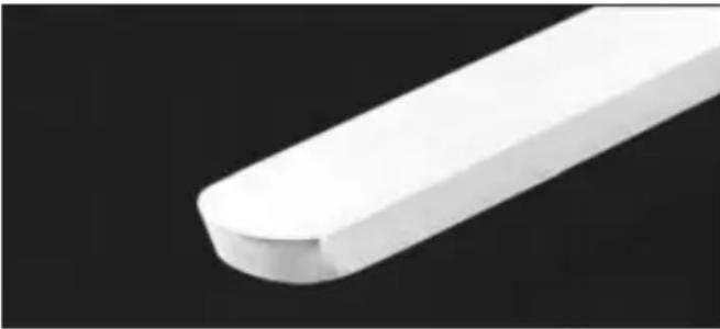 |
| Parting Tools—Used for sizing and cutti off work. This is a flat tool with a sha pointed nose that may be single- or do ground. |  |
| Specialty Tools—These are the unique, special function tools to aid in hollowing bowl making, cutting profiles, etc. |
- For safety and best performance, keep tools sharp. If a tool stops cutting or requires excessive pressure to make a cut, it needs to be sharpened. A nu brand name sharpening jigs and fixtures are available; however, a woodturner should learn to sharpen tools freehand.
- For best results, use a slow speed grinder (1800 rpm) fitted with a 60-grit aluminum oxide wheel (for shaping) and a 100-grit alum. oxide wheel (for fir sharpening and touchup). The grinder should be located near your lathe and comfortable height. A diamond dresser will keep the wheels true and eliminate glazing.
- Never allow the tool to rest in one place on the wheel, keep it moving and light touch.
- Carbon steel tools can overheat easily and should be cooled frequently. If the edge turns blue, it has lost its temper and should be ground past the blue High-speed steel tools are not as likely to overheat, but can be damaged if
allowed to get red hot. High-speed steel tools should not be quenched for a Honing with a diamond lap or slipstone will save trips to the grinder and keep edge fresh quenched for cooling. Honing with a diamond lap or slipstone will keep trips to the grinder and keep the edge fresh.
9.3 Spindle Turning
Spindle turning takes place between the centers of the lathe. It requires a spur center in the headstock and a live or dead center in the tailstock. A cup center than a cone center in the tailstock will often reduce the risk of splitting the stock
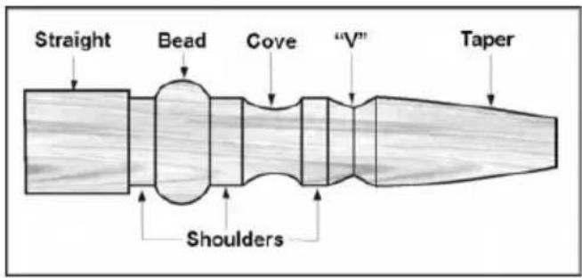
9.4 Stock Selection
Stock for spindles should be straight grained and free of checks, cracks, knots a other defects. It should be cut 1/8" to 1/4" larger than the finished diameter and require additional length so the ends can be removed later. Larger stock should the corners removed to produce an octagon making the piece easier to rough do a cylinder.
-
With a combination square, or plastic center finder for round stock, locate and mark center on each end of the workpiece. Accuracy is not critical on full but extremely important on stock where square sections are to remain. Put a dimple in the stock with an awl or nail, or use a spring-loaded automatic c punch.
-
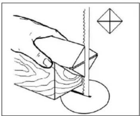
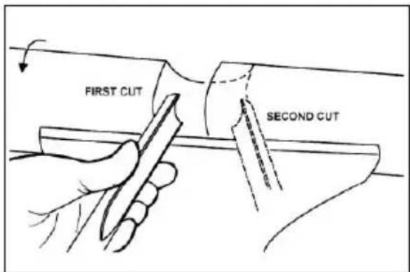
Extremely hard woods may require kerfs cut into the ends of the stock using band saw, so the wood will accept the spur center and the live center
natural_image
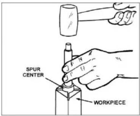
Diagram showing a hand using a sawtooth tool to cut wood grain, with a geometric symbol nearby (no text or labels)- Drive the spur center about 1/4" into the workpiece, using a wood mallet or blow hammer. Be careful that you do not split the workpiece.
-
Make sure headstock is locked to lathe bed.
-
Clean tapered end of spur center and inside of headstock spindle.
-
Insert tapered end of spur center (with the attached workpiece) into headstock spindle.
-
Support the workpiece while bringing the tailstock into position about 1-inch air from end of workpiece. Lock tailstock to bed.
-
Advance tailstock quill with the handwheel in order to seat the live center into workpiece. Use enough pressure to secure the workpiece between the center that it won't fly off, but do not use excessive pressure.
-
Tighten quill locking handle.
-
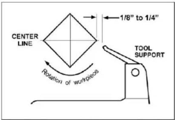
Move tool rest into position. It should be parallel to workpiece, just below the center line and approximately 1/8" to 1/4" from the corners of the workpiece turned. Tighten tool rest base to Lathe bed.
-
Rotate workpiece by hand to check for proper clearance.
-
Start lathe at lowest speed and bring it up to the appropriate RPM for the workpiece used. Consult digital readout on the headstock.
9.5 Cutting Techniques
9.5.1 Roughing Out
- Begin with a large roughing gouge. Place the tool on the tool rest with the the tool on the surface to be cut.
- Slowly and gently raise tool handle until cutting edge comes into contact with workpiece.
- Beginning about 2" from the tailstock end of the workpiece, roll the flute (hollowed-out portion) of the tool in the direction of the cut. Make long swe cuts in a continuous motion to rough the piece down to a cylinder.
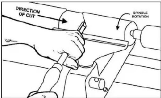
- Keep as much of the bevel of the tool as possible in contact with the work ensure control and avoid catches. NOTE: Always cut down-hill, or from large diameter to small diameter. Always work toward the end of a work-piece, next start cutting at the end.
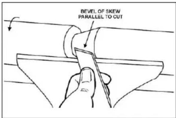
- Once the workpiece is roughed down to a cylinder, smooth it with a large s Keep the skew handle perpendicular to the spindle and use only the center of the cutting edge for a long smoothing cut (touching one of the points of skew to the spinning workpiece may cause a catch and ruin the workpiece).
- Add details to the workpiece with skew, parting tool, scraper or spindle gouge
9.5.2 Beads
- Make a parting cut for what is to be a bead to the desired depth. Place the tool on the tool support and move tool forward to make the full bevel of the come into contact with the workpiece. Gently raise handle to make cut to the appropriate depth.
- Repeat for other side of the bead.
- Using a small skew or spindle gouge, start in the center between the two cut down each side to form the bead. Roll the tool in direction of cut.
9.5.3 Coves
- Use a spindle gouge. With the flute of the tool at 90 degrees to the workpiece touch the point of the tool to the workpiece and roll in towards the bottom cove. Stop at the bottom; attempting to go up the opposite side may cause tool to catch.
- Move the tool over the desired width of the cove.
- With the flute facing the opposite direction, repeat step 1 for other side of c Stop at bottom of cut.
9.5.4 "V" Cuts
- Use the long point of the skew. (NOTE: Do not press the long point of the directly into the workpiece to create the "V"; this will result in a burned or burnished "V" with fibers being rolled up at both sides.)
- Lightly mark the center of the "V" with the tip of the skew.
- Move the point of the skew to the right half of the desired width of your c
- With the bevel parallel to the right side of the cut, raise the handle and put tool in to the desired depth.
- Repeat from the left side. The two cuts should meet at the bottom and leave clean "V" cut.
- Additional cuts may be taken to add to either the depth or width of the cut
9.5.5 Parting Off
- Use parting tool.
- Adjust lathe speed to lower RPM for parting through a workpiece.
- Place tool on tool support and raise the handle until it starts to cut and cut toward center of workpiece.
- Loosely hold on to the piece in one hand as it separates from the waste w
9.5.6 Sanding and Finishing
-
Leaving clean cuts will reduce the amount of sanding required. Move the tool support out of the way, adjust the lathe to a low speed, and begin with f sandpaper (120 grit or finer). Coarser sandpaper will leave deep scratches th are difficult to remove, and dull crisp details on the spindle. Progress through each grit without skipping grits (for example, do not jump from 120 grit to Fold the sandpaper into a pad; do not wrap sandpaper around your fingers workpiece.To apply a finish, the workpiece can be left on the lathe.
-
Turn off lathe and use a brush or paper towel to apply the finish. Remove finish before restarting lathe. Allow to dry and sand again with 320 or 400 sandpaper. Apply second coat of finish and buff.
9.6 Face Plate and Bowl Turning
Face plate turning is normally done on the inboard side of the headstock over bed. Larger workpieces must be turned on the outboard side. Rotate headstock to desired position; or remove tailstock and tool support base, and slide headstock to opposite end of bed.
9.6.1 Mounting Stock
Use of a face plate is the most common method for holding a block of wood bowls and plates:
- Select stock at least 1/8" to 1/4" larger than each dimension on the finished workpiece.
- Always select the largest diameter face plate that can be used for the work to be turned.
- True one surface of the workpiece for mounting against the face plate.
- Using the face plate as a template, mark the location of the mounting holes workpiece, and drill pilot holes of the appropriate size. Face plates are drilled No. 12 screws. (Phillips and square drive screws will hold up better than sl screws. Sheel metal screws are case hardened with deeper and sharper thre
than wood screws.) If the mounting screws on the face plate interfere with workpiece, a glue or waste block can be used:
- Make a block the same diameter as the face plate. Both waste block and workpiece should have flat surfaces for gluing.
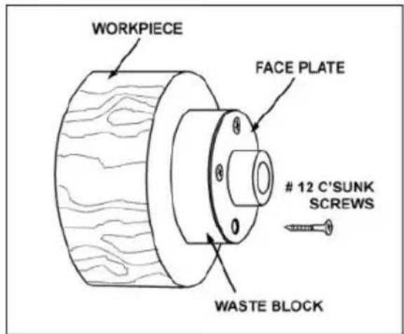
- Glue the block to the workpiece. Avoid using brown paper or newspaper between the waste block and workpiece. It may work fine if you are using scrapers, slight catch with a bowl gouge can separate the two.
NOTE: When using a waste block, be careful with the adhesive you select. Dry workpieces can be bonded with ordinary white or yellow glue but must be clamp ensure a good bond. Green workpieces require cyanoacrylate type glue.
9.6.2 Faceplate or Chuck
● While faceplates are the simplest, most reliable method of holding a block of wood for turning, chucks can also be used.
- As there are dozens of chucks to choose from, the woodturner should first consider all the different types of turning that will be done, and read reports discuss with other turners who own chucks before making a decision.
- A chuck is not a requirement, but is handy when working on more than one at a time. Rather than removing screws, you simply open the chuck and ch workpieces.
● The most popular ones are four jaw scroll chucks with a variety of jaws to accommodate different size tenons. Most also come with a screw chuck as
9.6.3 Wood Selection
Firewood is the cheapest, most widely available stock to use while learning 1 bowls. Simply waste wood for a while practicing turning techniques. Develop skill each tool before attempting to make a finished piece. It is best to start with dry
without worrying about drying or distortion. Once turning becomes comfortable, try green wood which cuts very easily. As the turner gains experience, he or she will be extraordinary grain and figure in the form of burls, crotches and bark inclusions.
9.6.4 Checks and Cracks
- Green wood will check and crack. For best results, leave logs in as long as you can handle. As the material starts to dry, surface cracks will develop ends of the log. Cut off two to three inches and you should find good, so Also cut the log in half along the pith to avoid having it in the finished pie checks radiate from the pith.
- As you turn bowls from green wood, make sure you maintain a consistent wall thickness throughout the piece. Leaving a piece thick in some areas and this others will cause the wood to dry unevenly and promote checks and cracks.
9.6.5 Distortion
Distortion is a problem associated with turning green wood. It will vary from one wood to the next. Typically, fruitwoods tend to distort more than others. It also with the time of year the tree was cut and how the logs are stored.
9.6.6 Tools for Bowl Turning
- The deep fluted bowl gouge is the most essential and versatile tool for most and plate turning. The bowl gouge is heavier and easier to control than oth types of gouges. It also allows removal of wood much faster and with less vibration than other gouges. Most average sized bowl work can be accomplis with a 3/8" or 1/2" bowl gouge.
- A 1/4" bowl gouge is best suited for smaller bowls and light finishing cuts. L 3/4" and 1" bowl gouges are only used for extremely large pieces.
- Large domed scrapers can also be used to help clean up the interior surface bowls. A light touch with the scraper slightly tilted will eliminate some of the occasionally left by an inexperienced bowl gouge.
9.7 Bowl Turning Techniques
9.7.1 To Shape Outside of Bowl
- Odd shaped burls, crotches and other irregular shaped blanks require special preparation before mounting in a chuck or onto a faceplate. Remove the bar there is any, from what appears to be the center of the top of the workpie
-
Drive spur center into the top of the workpiece with a mallet or dead blow hammer.
-
Slip the spur center into the headstock taper and bring the tailstock with a I ball bearing center into position. Lock the tailstock to the bed and advance tailstock spindle in order to seat the cup center into the workpiece. Tighten ram locking handle.
- Turn workpiece by hand to ensure proper clearance.
- Start lathe at lowest speed and bring it up to the maximum safe speed for of work to be turned. If the machine starts to vibrate, lower the speed until vibration stops.
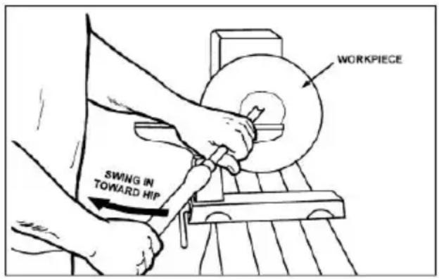
- Rough out the outside of the bowl with the 1/2" deep fluted bowl gouge, how the handle of the tool firmly against your hip. For best control, use your white body to move the gouge through the workpiece.
- As the bowl takes shape, work on the bottom (tailstock end) to accommodate attaching a face plate.
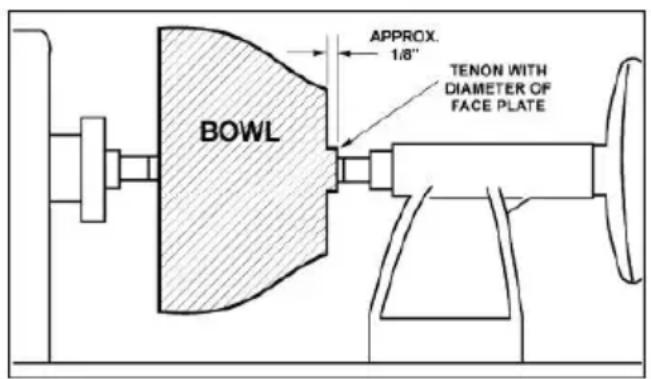
- Turn a short tenon (about 1/8" long) the size of the hole in the faceplate. I allow centering the workpiece when the faceplate is attached. (NOTE: If you to use a chuck, turn a tenon of the appropriate length and diameter to fit chuck.)
-
Stop the lathe, remove workpiece and attach face plate or chuck. The surfaces of faceplate and workpiece should mount flush to each other.
-
Finish turning the outside of bowl with 1/2" or 3/8" bowl gouge. Leave addi material at base of bowl for support while turning interior. This will be remo later.
9.7.2 To Shape Interior of Bowl
- Stop lathe and move tailstock away. (You may want to remove the center from tailstock to avoid bumping it with your elbow.)
-
Adjust tool support in front of the bowl just below center line, at a right angle lathe ways.
-
Rotate workpiece by hand to check clearance.
- Face off top of bowl by making a light shearing cut across the top of work from rim to center.
- Place 1/2" bowl gouge on tool support at center of the workpiece with the fl facing top of bowl. The tool handle should be level and pointed toward the o'clock position.
- Use the left hand to control cutting edge of gouge, while right hand swings handle toward your body. The flute should start out facing top of workpiece, rotate upward as it moves deeper into the bowl to maintain a clean even of the tool goes deeper into the bowl, progressively work out toward the rim. I be necessary to turn the tool support into the piece as you get deeper into a bowl.
- Develop wall thickness at the rim and maintain it as you work deeper into the (Once the piece is thin toward the bottom, you cannot make it thinner at the). When the interior is finished, move the tool support to exterior to re-define of bowl. (General rule of thumb: the base should be approximately 1/3 the diameter of the bowl).
- Work the tight area around faceplate or chuck with 1/4" bowl gouge.
- Begin the separation with a parting tool, but do not cut all the way through
9.7.3 Sanding and Finishing
- Remove the tool support and adjust lathe speed to approximately 500 RPM. Higher speeds can build friction while sanding and cause heat check in some woods.
- Begin with fine sandpaper (120 grit) and progress through each grit, using or light pressure. Coarser sandpaper tends to leave deep scratches that are halimate. Use power-sanding techniques to avoid concentric sanding marks
around your finished piece. Avoid rounding over the rim and foot with sandp try to keep details crisp. Finish sanding with 220 grit.
- Remove sanding dust with tack rags or compressed air and, with lathe turned apply first coat of finish. Let stand for several minutes, wipe off excess. All dry before sanding again with 320 or 400 grit sandpaper.
- Turn lathe back on and continue the separation cut almost all the way through base. Stop at about 3" and use a small fine tooth saw to separate the both the waste.
- Apply second finish coat and allow to dry before buffing.
MAINTENANCE
Before doing maintenance on the lathe, disconnect it from the electrical supply by pulling out the plug or switching off the main switch. Failure to may cause serious injury.
10.1 General procedures
- Maintenance on the 1218 lathe should be performed at periodic intervals to ensure that the machine is in proper working order, that all fasteners are tied to all necessary adjustments have been made. Inspection and maintenance should be performed at least twice a year, but more frequently if the lathe receives constant use.
- Clean and oil the lathe bed so that headstock, tailstock and tool rest base w slide easily. Clean any rust spots that may develop on the bed with a corr rust remover.
- Use compressed air to blow out the interior of the headstock, in order to keep sawdust and chips from accumulating on belts and sheaves. Also blow off that accumulates in the motor fan and around inverter. Do not disassemble inverter to clean!
- Frequently clean out the morse tapers on both headstock and tailstock. Commercially available taper cleaners may be acquired from tool stores.
● Bearings are permanently lubricated and sealed, and do not require further lubrication.
10.2 Pulley and belt alignment
- The motor and spindle pulleys are aligned with each other by the manufacture but if any service is performed that affects their alignment it is very important they be realigned. Engage spindle lock, loosen two set screws on spindle put (E, Figure 9-12) with 3mm hex key, and slide spindle pulley into proper post Retighten set screws, and disengage spindle lock.
- When pulleys and belt are properly aligned, there should be no unusual pulsir sounds or noise coming from the belt.
10.3 Belt replacement
To change out a belt or pulley, carefully proceed as follows. If you are uncertain attempting a belt or pulley change-out, contact technical service or take the head to an authorized service center.
- Disconnect lathe from power source.
- Loosen pivot lock handle and lift up tension handle to raise motor.
- Tighten pivot lock handle to secure motor in raised position.
- Slip belt off pulleys.
- Loosen set screws on handwheel.
- Unscrew handwheel from spindle.
- Unsling Ring retaining from spindle.
- Slide spindle a little way out of headstock, just enough to remove pulley or NOTE: If needed, tap end of spindle with a wood block or rubber mallet to Do not use a steel face hammer directly against spindle.
- If replacing a pulley, loosen both set screws, and slide pulley off spindle.
- Install new pulley, loosely securing the two set screws. Make sure pulley is oriented properly and key is inserted properly in spindle groove.
- Slide spindle back into place.
- Reinstall Ring retaining.
- Reinstall handwheel and tighten set screws.
- Align new pulley then tighten both set screws securely on pulley.
- Loosen pivot lock handle and lower motor using tension handle.
TROUBLESHOOTING LATHE
| Symptom | Possible Cause | Correction |
| Motor fails to develop full power | Power line overloaded. | Correct overload condition. |
| Undersized wires in supply system, extension cord is too long | Increase supply wire size | |
| Low voltage | Request voltage check from power company and correct low voltage condit | |
| Worn motor | Replace motor | |
| Motor or spindle stalls or will not start. | Excessive cut. | Reduce depth of cut |
| Worn or broken belt. | Replace belt. | |
| Improper cooling of motor | Blow out sawdust from motor housing | |
| Worn spindle bearings | Replace bearings | |
| Worn motor | Replace motor | |
| Excessive vibration or noises | Workpiece warped, out of round, has major flaw, was improperly prepared turning | Correct problem by planing or sawing workpiece, or discard entirely and use workpiece |
| Spindle rotation too fast | Reduce speed | |
| Worn spindle bearings | Replace spindle bearings | |
| Drive belt misaligned or worn | Align belt. Replace if worn | |
| Motor mount bolts are loose. | Tighten bolts | |
| Lathe on uneven surface | Adjust leveling feet. | |
| Tools tend to grab or dig in. | Dull tools | Keep tools sharp |
| Tool rest set too low | Reposition tool rest height | |
| Tool rest set too far from workpiece | Reposition tool rest closer to workpiece | |
| Improper tool being used. | Use correct tool for operation. | |
| Tailstock moves when applying pressure. | Cam lock nut needs adjusting | Tighten cam lock nut |
| Excessive pressure being applied by tailstock. (Note: The screw action of tailstock is capable of applying excessive pressure to workpiece and headstock. Apply only sufficient force tailstock to hold workpiece securely place. Excessive pressure can cause damage to machine. | Slide tailstock to right side of lathe ag the stop. Move headstock into position apply pressure to workpiece with tailstoc | |
| Lathe bed and tailstock mating surfa are greasy or oily | Remove tailstock and clean surfaces wi cleaner/degreaser. Re-apply light coat of oil to lathe bed surface. | |
| Digital readout does not work | Digital sensor out of position. | Open belt access and position sensor that it reads the bolts |
Warning: Some corrections may require a qualified electrician.
RECOMMENDED LATHE SPEEDS (per diameter of workpiece)
| Diameter of Work | Roughing RPM | General Cutting RPM | Finishing RPM |
| Under 2" | 1520 | 3000 | 3000 |
| 2" to 4" | 760 | 1600 | 2290 |
| 4" to 6" | 510 | 1080 | 1500 |
| 6" to 8" | 380 | 810 | 1125 |
| 8" to 10" | 300 | 650 | 900 |
| 10" to 12" | 255 | 540 | 750 |
| 12" to 14" | 220 | 460 | 640 |
| 14" to 16" | 190 | 400 | 560 |
| 16" to 20" | 175 | 325 | 450 |
| 20" to 24" | 175 | 260 | 375 |
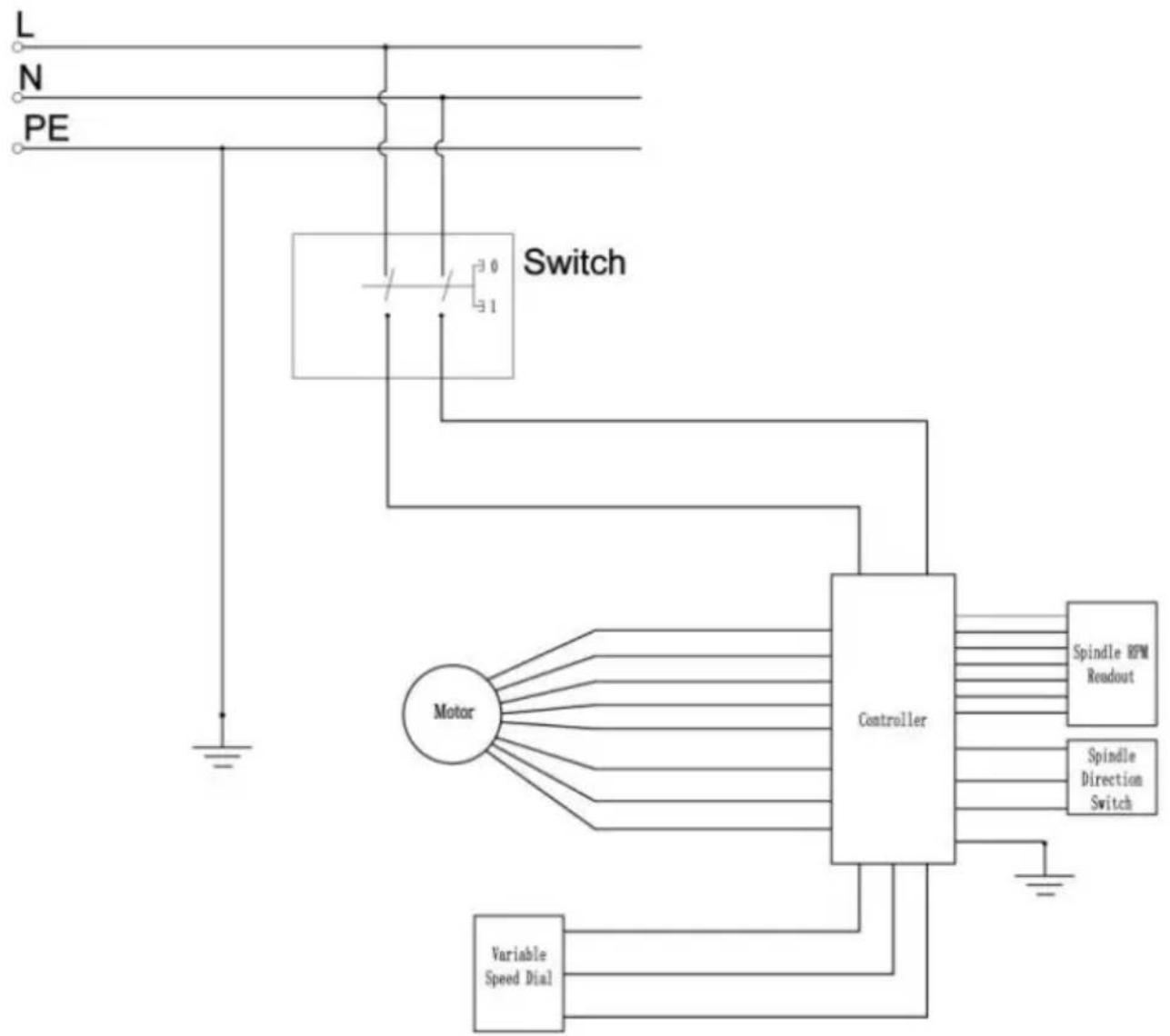
SCHALTPLAN/WIRING DIAGRAM

flowchart
graph TD
    L --> N
    N --> PE
    PE --> Switch
    Switch --> Motor
    Motor --> Controller
    Controller --> Spindle_RPM_Readout
    Controller --> Spindle_Direction_Switch
    Motor --> Variable_Speed_Dial
    Variable_Speed_Dial --> Control
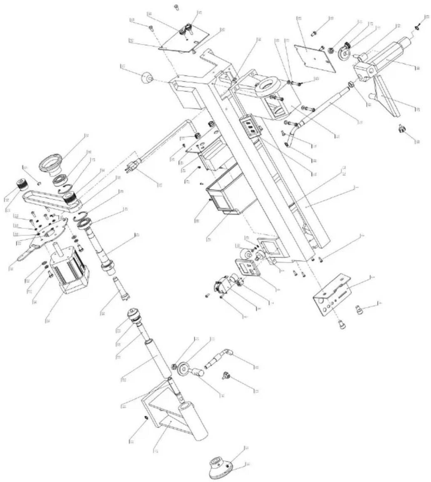
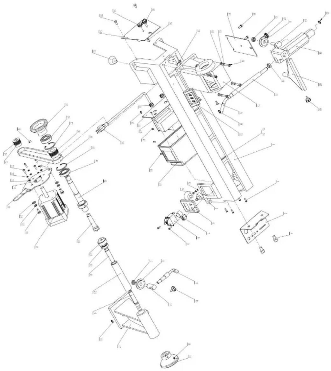
PARTS LIST
| NO. | DESCRIPTION | QTY | NO. | DESCRIPTION | QTY |
| 1 | Bed | 1 | 2 | Screw ST4.2×16 | 4 |
| 3 | Tool holder | 1 | 4 | Screw M10×20 | 2 |
| 5 | Variable Speed Dial | 1 | 6 | Plate | 1 |
| 7 | Spindle Direction Switch | 1 | 8 | Switch | 1 |
| 9 | Screw M4×20 | 2 | 10 | Hex. nut M10 | 2 |
| 11 | Lock plate | 2 | 12 | Eccentric axis | 1 |
| 13 | Lock lever | 1 | 14 | Bolt | 1 |
| 15 | Screw M6×6 | 6 | 16 | Handwheel | 1 |
| 17 | Tailstock | 1 | 18 | Ring retaining 10 | 1 |
| 19 | Tailstock quill | 1 | 20 | Tail axis | 1 |
| 21 | Taper rod | 1 | 22 | Bearing ball 6201 | 1 |
| 23 | Cup center | 1 | 24 | Headstock spur center | 1 |
| 25 | Motor | 1 | 26 | Screw M8×16 | 2 |
| 27 | Spring washer 8 | 2 | 28 | Flat washer 8 | 2 |
| 29 | Motor plate | 1 | 30 | Flat key 6×40 | 1 |
| 31 | Flat washer 5 | 4 | 32 | Spring washer 5 | 4 |
| 33 | Screw M5×16 | 4 | 34 | Motor pulley | 1 |
| 35 | Handwheel | 1 | 36 | Bearing ball 6005 | 1 |
| 37 | Ring retaining 47 | 1 | 38 | Drive pulley | 1 |
| 39 | Drive belt | 1 | 40 | Ring retaining 47 | 1 |
| 41 | Bearing ball 6204 | 1 | 42 | Headstock spindle | 1 |
| 43 | Washer 4 | 4 | 44 | screw M4×10 | 2 |
| 45 | Switch box | 1 | 46 | screw M3×6 | 4 |
| 47 | Isolation column | 4 | 48 | Circuit board | 1 |
| 49 | Plate | 1 | 50 | Screw ST3.5×16 | 4 |
| 51 | Wire Clamp | 2 | 52 | Power cord | 1 |
| 53 | Rubber washer | 4 | 54 | Side plate | 1 |
| 55 | Screw M6×10 | 3 | 56 | Stationary knob | 1 |
| 57 | Moving knob | 2 | 58 | Screw M6×12 | 1 |
| 59 | Cable Clamp | 2 | 60 | Flat washer 6 | 4 |
| 61 | Spring washer 6 | 4 | 62 | Screw M6×30 | 4 |
| 63 | Back lid | 1 | 64 | Bolt | 1 |
| 65 | Ring retaining 12 | 2 | 66 | Tool rest base | 1 |
| 67 | Tool rest | 1 | 68 | Lock lever | 1 |
| 69 | Cover | 1 | 70 | Lock handle for knife base | 1 |
| 71 | Screw M5×12 | 2 | 72 | Spindle RPM Readout | 1 |
| 73 | Cable Clamp | 2 | 74 | Screw M4×12 | 2 |
| 75 | Headstock | 1 |
Manufacturer: Shanghaimuxinmuyeyouxiangongsi
Address: Shuangchenglu 803nong11hao1602A-1609shi, baoshanqu, shanghai 200000 CN.
Imported to AUS: SIHAO PTY LTD. 1 ROKEVA STREETEASTWOOD NSW 2122 Australia
Imported to USA: Sanven Technology Ltd. Suite 250, 9166 Anaheim Place, Rancho Cucamonga, CA 91730
| UK | REP |
YH CONSULTING LIMITED. C/O YH Consulting
Limited Office 147, Centurion House, London Road, Staines-upon-Thames, Surrey, TW18 4AX
| EC | REP |
E-CrossStu GmbH
Mainzer Landstr.69,
60329 Frankfurt am Main.

VEVOR
Affordable. Reliable. Home Improvement.
TOUR À BOIS
MODÈLE : WL1218V
VEVOR
Affordable. Reliable. Home Improvement.
WOOD LATHE
MODÈLE : WL1218V

natural_image
Technical line drawing of a lathe machine with dual levers and control panel (no text or symbols)SAFETY INSTRUCTIONS FOR MACHINERY
natural_image
Technical line drawing of a mechanical assembly with mounting flanges and a control panel (no text or symbols)POWER SUPPLY
natural_image
Technical diagram of a mechanical assembly with labeled component C (no readable text or symbols)Porte-outil
natural_image
Mechanical device with lever and base mount (no visible text or symbols)Plaque frontale : Installation/Retrait
natural_image
Mechanical device with a vertical rod and control panel (no visible text or symbols)natural_image
Diagram showing a hand using a tool to cut a surface with a diamond-shaped symbol nearby (no text or labels)TROUBLESHOOTING LATHE
RECOMMENDED LATHE SPEEDS (per diameter of workpiece)
| Diameter of Work | Roughing RPM | General Cutting RPM | Finishing RPM |
| Under 2" | 1520 | 3000 | 3000 |
| 2" to 4" | 760 | 1600 | 2290 |
| 4" to 6" | 510 | 1080 | 1500 |
| 6" to 8" | 380 | 810 | 1125 |
| 8" to 10" | 300 | 650 | 900 |
| 10" to 12" | 255 | 540 | 750 |
| 12" to 14" | 220 | 460 | 640 |
| 14" to 16" | 190 | 400 | 560 |
| 16" to 20" | 175 | 325 | 450 |
| 20" to 24" | 175 | 260 | 375 |
SCHALTPLAN/WIRING DIAGRAM

flowchart
graph TD
    L["Power Supply L"] --> Switch["Switch"]
    N["Power Supply N"] --> Switch
    PE["Power Input PE"] --> Switch
    Switch --> Motor["Motor"]
    Motor --> Controller["Controller"]
    Controller --> Spindle_RPM["Spindle RPM Readout"]
    Controller --> Spindle_Direction["Spindle Direction Switch"]
    Motor --> Variable_Speed_Dial["Variable Speed Dial"]
    Control --> Control
EXPLOSIONSZEICHNUNG / EXPLOSION DRAWING

PARTS LIST
Lieu, Rancho Cucamonga, CA 91730
| UK | REP |
YH CONSULTING LIMITED. C/O YH Consulting Limited Office 147, Centurion House, London Road, Staines-upon-Thames, Surrey, TW18 4AX
| EC | REP |
Affordable. Reliable. Home Improvement.
DRECHSELBANK
MODELL: WL1218V
VEVOR
Affordable. Reliable. Home Improvement.
WOOD LATHE
MODELL: WL1218V

natural_image
Line drawing of a mechanical lathe machine with dual levers and control panel (no text or symbols)natural_image
Technical line drawing of a mechanical assembly with mounting flanges and control panel (no text or symbols)POWER SUPPLY
natural_image
Technical diagram of a mechanical assembly with labeled component C (no readable text or symbols)Werkzeugablage
natural_image
Mechanical device with lever and base mount (no visible text or symbols)natural_image
Mechanical device with a vertical rod and control panel, no visible text or symbols9.4 Aktienauswahl
natural_image
Diagram showing a hand using a sawtooth tool to cut a circular object, with a geometric symbol nearby (no text or labels)TROUBLESHOOTING LATHE
RECOMMENDED LATHE SPEEDS (per diameter of workpiece)
| Diameter of Work | Roughing RPM | General Cutting RPM | Finishing RPM |
| Under 2" | 1520 | 3000 | 3000 |
| 2" to 4" | 760 | 1600 | 2290 |
| 4" to 6" | 510 | 1080 | 1500 |
| 6" to 8" | 380 | 810 | 1125 |
| 8" to 10" | 300 | 650 | 900 |
| 10" to 12" | 255 | 540 | 750 |
| 12" to 14" | 220 | 460 | 640 |
| 14" to 16" | 190 | 400 | 560 |
| 16" to 20" | 175 | 325 | 450 |
| 20" to 24" | 175 | 260 | 375 |
SCHALTPLAN/WIRING DIAGRAM

flowchart
graph TD
    L["Power Supply L"] --> Switch["Switch"]
    N["Power Supply N"] --> Switch
    PE["Power Input PE"] --> Switch
    Switch --> Motor["Motor"]
    Motor --> Controller["Controller"]
    Controller --> Spindle_HPM["Spindle HPM Readout"]
    Controller --> Spindle_Direction["Spindle Direction Switch"]
    Motor --> Variable_Speed_Dial["Variable Speed Dial"]
    Control --> Control
EXPLOSIONSZEICHNUNG / EXPLOSION DRAWING

PARTS LIST
YH CONSULTING LIMITED. C/O YH Consulting
Limited Office 147, Centurion House, London Road, Staines-upon-Thames, Surrey, TW18 4AX
| EC | REP |
E-CrossStu GmbH
Mainzer Landstr.69,
60329 Frankfurt am Main.

VEVOR
Affordable. Reliable. Home Improvement.
TORNIO PER LEGNO
MODELLO: WL1218V
VEVOR
Affordable. Reliable. Home Improvement.
WOOD LATHE
MODELLO: WL1218V

natural_image
Technical line drawing of a lathe machine with dual levers and control panel (no text or symbols)SAFETY INSTRUCTIONS FOR MACHINERY
natural_image
Technical line drawing of a mechanical assembly with mounting holes and control panel (no text or symbols)POWER SUPPLY
natural_image
Technical diagram of a mechanical assembly with labeled component C (no readable text or symbols)natural_image
Mechanical device with articulated arm and base mount (no visible text or symbols)natural_image
Mechanical device with a digital display and lever mechanism (no visible text or symbols)natural_image
Diagram showing a hand using a sawtooth tool to cut a circular object, with a geometric symbol nearby (no text or labels)TROUBLESHOOTING LATHE
RECOMMENDED LATHE SPEEDS (per diameter of workpiece)
| Diameter of Work | Roughing RPM | General Cutting RPM | Finishing RPM |
| Under 2" | 1520 | 3000 | 3000 |
| 2" to 4" | 760 | 1600 | 2290 |
| 4" to 6" | 510 | 1080 | 1500 |
| 6" to 8" | 380 | 810 | 1125 |
| 8" to 10" | 300 | 650 | 900 |
| 10" to 12" | 255 | 540 | 750 |
| 12" to 14" | 220 | 460 | 640 |
| 14" to 16" | 190 | 400 | 560 |
| 16" to 20" | 175 | 325 | 450 |
| 20" to 24" | 175 | 260 | 375 |
SCHALTPLAN/WIRING DIAGRAM

flowchart
graph TD
    L["Power Supply L"] --> Switch["Switch"]
    N["Power Supply N"] --> Switch
    PE["Power Input PE"] --> Switch
    Switch --> Motor["Motor"]
    Motor --> Controller["Controller"]
    Controller --> Spindle_RPM["Spindle RPM Readout"]
    Controller --> Spindle_Direction["Spindle Direction Switch"]
    Motor --> Variable_Speed_Dial["Variable Speed Dial"]
    Control --> Control
EXPLOSIONSZEICHNUNG / EXPLOSION DRAWING

PARTS LIST
YH CONSULTING LIMITED. C/O YH Consulting Limited Office 147, Centurion House, London Road, Staines-upon-Thames, Surrey, TW18 4AX
| EC | REP |
Affordable. Reliable. Home Improvement.
TORNO DE MADERA
MODELO: WL1218V
VEVOR
Affordable. Reliable. Home Improvement.
WOOD LATHE
MODELO: WL1218V

natural_image
Technical line drawing of a lathe machine with dual levers and control panel (no text or symbols)SAFETY INSTRUCTIONS FOR MACHINERY
natural_image
Technical line drawing of a mechanical assembly with mounting flanges and control panel (no text or symbols)POWER SUPPLY

natural_image
Technical diagram of a mechanical assembly with labeled component C (no text or symbols beyond label)natural_image
Mechanical device with lever and base mount (no visible text or symbols)natural_image
Mechanical device with a vertical rod and control panel (no visible text or symbols)natural_image
Diagram showing a hand using a sawtooth tool to cut a circular object, with a geometric symbol nearby (no text or labels)TROUBLESHOOTING LATHE
RECOMMENDED LATHE SPEEDS (per diameter of workpiece)
| Diameter of Work | Roughing RPM | General Cutting RPM | Finishing RPM |
| Under 2" | 1520 | 3000 | 3000 |
| 2" to 4" | 760 | 1600 | 2290 |
| 4" to 6" | 510 | 1080 | 1500 |
| 6" to 8" | 380 | 810 | 1125 |
| 8" to 10" | 300 | 650 | 900 |
| 10" to 12" | 255 | 540 | 750 |
| 12" to 14" | 220 | 460 | 640 |
| 14" to 16" | 190 | 400 | 560 |
| 16" to 20" | 175 | 325 | 450 |
| 20" to 24" | 175 | 260 | 375 |
SCHALTPLAN/WIRING DIAGRAM

flowchart
graph TD
    L --> Switch
    N --> Switch
    PE --> Switch
    Switch --> Motor
    Motor --> Controller
    Controller --> Spindle_RPM_Routout
    Controller --> Spindle_Direction_Switch
    Motor --> Variable_Speed_Dial
    Variable_Speed_Dial --> Control
EXPLOSIONSZEICHNUNG / EXPLOSION DRAWING

PARTS LIST
YH CONSULTING LIMITED. C/O YH Consulting
Limited Office 147, Centurion House, London
Road, Staines-upon-Thames, Surrey, TW18 4AX
| EC | REP |
E-CrossStu GmbH
Mainzer Landstr.69,
60329 Frankfurt am Main.

VEVOR
Affordable. Reliable. Home Improvement.
TOKARKA DO DREWNA
MODEL:WL1218V
VEVOR
Affordable. Reliable. Home Improvement.
WOOD LATHE
MODEL:WL1218V

natural_image
Technical line drawing of a lathe machine with dual levers and control panel (no text or symbols)SAFETY INSTRUCTIONS FOR MACHINERY
natural_image
Technical line drawing of a mechanical assembly with no visible text or symbolsPOWER SUPPLY
natural_image
Technical diagram of a mechanical assembly with labeled component C (no readable text or symbols)natural_image
Mechanical device with lever and base mount (no visible text or symbols)natural_image
3D rendering of a mechanical device with a vertical pole and control panel (no visible text or symbols)OPERATING CONTROLS
natural_image
Close-up of a white plastic sheet with a curved cutout, against a black background (no text or symbols)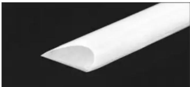
natural_image
Close-up of a white curved plastic or tube against a black background (no text or symbols visible)9.4 Wybór akcji
natural_image
Diagram showing a hand using a sawtooth tool to cut wood grain, with a geometric symbol nearby (no text or labels)TROUBLESHOOTING LATHE
RECOMMENDED LATHE SPEEDS (per diameter of workpiece)
| Diameter of Work | Roughing RPM | General Cutting RPM | Finishing RPM |
| Under 2" | 1520 | 3000 | 3000 |
| 2" to 4" | 760 | 1600 | 2290 |
| 4" to 6" | 510 | 1080 | 1500 |
| 6" to 8" | 380 | 810 | 1125 |
| 8" to 10" | 300 | 650 | 900 |
| 10" to 12" | 255 | 540 | 750 |
| 12" to 14" | 220 | 460 | 640 |
| 14" to 16" | 190 | 400 | 560 |
| 16" to 20" | 175 | 325 | 450 |
| 20" to 24" | 175 | 260 | 375 |
SCHALTPLAN/WIRING DIAGRAM

flowchart
graph TD
    L["Power Supply L"] --> Switch["Switch"]
    N["Power Supply N"] --> Switch
    PE["Power Input PE"] --> Switch
    Switch --> Motor["Motor"]
    Motor --> Controller["Controller"]
    Controller --> Spindle_RPM["Spindle RPM Readout"]
    Controller --> Spindle_Direction["Spindle Direction Switch"]
    Motor --> Variable_Speed_Dial["Variable Speed Dial"]
    Control --> Control
EXPLOSIONSZEICHNUNG / EXPLOSION DRAWING
PARTS LIST
YH CONSULTING LIMITED. C/O YH Consulting
Limited Office 147, Centurion House, London
Road, Staines-upon-Thames, Surrey, TW18 4AX
| EC | REP |
E-CrossStu GmbH
Mainzer Landstr.69,
60329 Frankfurt am Main.

VEVOR
Affordable. Reliable. Home Improvement.
HOUTDRAAIBANK
MODEL: WL1218V
VEVOR
Affordable. Reliable. Home Improvement.
WOOD LATHE
MODEL: WL1218V

natural_image
Technical line drawing of a lathe machine with dual levers and control panel (no text or symbols)SAFETY INSTRUCTIONS FOR MACHINERY
WAARSCHUWING
natural_image
Technical line drawing of a mechanical device with mounting holes and control panel (no text or symbols)POWER SUPPLY
natural_image
Technical diagram of a mechanical assembly with labeled component C (no text or symbols beyond label)natural_image
Mechanical device with a lever and base mount, no visible text or symbolsnatural_image
Mechanical device with a vertical pole and control panel, no visible text or symbolsOPERATING CONTROLS
natural_image
Diagram showing a hand using a sawtooth tool to cut a wooden block with a diamond-shaped symbol nearby (no text or labels)TROUBLESHOOTING LATHE
RECOMMENDED LATHE SPEEDS (per diameter of workpiece)
| Diameter of Work | Roughing RPM | General Cutting RPM | Finishing RPM |
| Under 2" | 1520 | 3000 | 3000 |
| 2" to 4" | 760 | 1600 | 2290 |
| 4" to 6" | 510 | 1080 | 1500 |
| 6" to 8" | 380 | 810 | 1125 |
| 8" to 10" | 300 | 650 | 900 |
| 10" to 12" | 255 | 540 | 750 |
| 12" to 14" | 220 | 460 | 640 |
| 14" to 16" | 190 | 400 | 560 |
| 16" to 20" | 175 | 325 | 450 |
| 20" to 24" | 175 | 260 | 375 |
SCHALTPLAN/WIRING DIAGRAM
flowchart
graph TD
    L["Power Supply L"] --> Switch["Switch"]
    N["Power Supply N"] --> Switch
    PE["Power Input PE"] --> Switch
    Switch --> Motor["Motor"]
    Motor --> Controller["Controller"]
    Controller --> Spindle_HPM["Spindle HPM Readout"]
    Controller --> Spindle_Direction["Spindle Direction Switch"]
    Motor --> Variable_Speed_Dial["Variable Speed Dial"]
    Control --> Control
    Motor --> Control
EXPLOSIONSZEICHNUNG / EXPLOSION DRAWING

PARTS LIST
YH CONSULTING LIMITED. C/O YH Consulting
Limited Office 147, Centurion House, London
Road, Staines-upon-Thames, Surrey, TW18 4AX
| EC | REP |
E-CrossStu GmbH
Mainzer Landstr.69,
60329 Frankfurt am Main.

VEVOR
Affordable. Reliable. Home Improvement.
TRÄSVARV
MODELL: WL1218V
VEVOR
Affordable. Reliable. Home Improvement.
WOOD LATHE
MODELL: WL1218V
natural_image
Technical line drawing of a lathe machine with dual levers and control panel (no text or symbols)SAFETY INSTRUCTIONS FOR MACHINERY
natural_image
Technical line drawing of a mechanical device with mounting flanges and control panel (no text or symbols)POWER SUPPLY
natural_image
Mechanical device with lever and base mount (no visible text or symbols)Frontplatta: Montering/demontering
natural_image
Illustration of a mechanical device with a digital display and lever (no text or symbols visible)OPERATING CONTROLS
9.4 Aktieval
natural_image
Diagram showing a hand using a tool to cut a wooden block with a zigzag line, alongside a geometric symbol (diamond and square) with no readable text or labels.RECOMMENDED LATHE SPEEDS (per diameter of workpiece)
| Diameter of Work | Roughing RPM | General Cutting RPM | Finishing RPM |
| Under 2" | 1520 | 3000 | 3000 |
| 2" to 4" | 760 | 1600 | 2290 |
| 4" to 6" | 510 | 1080 | 1500 |
| 6" to 8" | 380 | 810 | 1125 |
| 8" to 10" | 300 | 650 | 900 |
| 10" to 12" | 255 | 540 | 750 |
| 12" to 14" | 220 | 460 | 640 |
| 14" to 16" | 190 | 400 | 560 |
| 16" to 20" | 175 | 325 | 450 |
| 20" to 24" | 175 | 260 | 375 |
SCHALTPLAN/WIRING DIAGRAM

flowchart
graph TD
    L["Power Supply L"] --> Switch["Switch"]
    N["Power Supply N"] --> Switch
    PE["Power Input PE"] --> Switch
    Switch --> Motor["Motor"]
    Motor --> Controller["Controller"]
    Controller --> Spindle_HPM["Spindle HPM Readout"]
    Controller --> Spindle_Direction["Spindle Direction Switch"]
    Motor --> Variable_Speed_Dial["Variable Speed Dial"]
    Control --> Control
EXPLOSIONSZEICHNUNG / EXPLOSION DRAWING

PARTS LIST
YH CONSULTING LIMITED. C/O YH Consulting
Limited Office 147, Centurion House, London
Road, Staines-upon-Thames, Surrey, TW18 4AX
| EC | REP |
E-CrossStu GmbH
Mainzer Landstr.69,
60329 Frankfurt am Main.