TLM2310-4S - Heat press Vevor - Free user manual and instructions
Find the device manual for free TLM2310-4S Vevor in PDF.

| Product Type | Heat Press |
| Brand | Vevor |
| Model | TLM2310-4S |
| Dimensions (package) | 56 × 31 × 40.5 cm (L × W × H) |
| Net Weight | 12.3 kg |
| Gross Weight | 13.7 kg |
| Power Supply (US) | 120 V ~ 50/60 Hz, 580 W |
| Power Supply (Europe) | 220-240 V ~ 50/60 Hz, 555 W |
| Adjustable Temperature Range | 0-299 °C (0-570 °F) |
| Timer Range | 0-999 seconds |
| Display | Digital (temperature and time) |
| Celsius/Fahrenheit Switch | Yes |
| Overload Protection | Fuse |
| On/Off Switch | Yes |
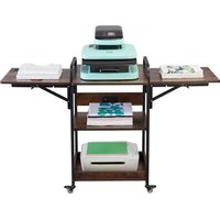
| Main Use | Transfer of patterns onto textiles, cups, plates |
| Safety Instructions | Do not disassemble, use a proper outlet, avoid moisture |
| Maintenance | Clean with a soft cloth, do not use abrasive products |
| Spare Parts | Heating plate, relay, fuse |
| Compliance | FCC Part 15, WEEE Directive 2012/19/EC |
Frequently Asked Questions - TLM2310-4S Vevor
User questions about TLM2310-4S Vevor
0 question about this device. Answer the ones you know or ask your own.
Ask a new question about this device
Download the instructions for your Heat press in PDF format for free! Find your manual TLM2310-4S - Vevor and take your electronic device back in hand. On this page are published all the documents necessary for the use of your device. TLM2310-4S by Vevor.
USER MANUAL TLM2310-4S Vevor
Technical Support and E-Warranty Certificate www.vevor.com/support
HEAT PRESS MACHINE USER MANUAL
We continue to be committed to provide you tools with competitive price. "Save Half", "Half Price" or any other similar expressions used by us only represents an estimate of savings you might benefit from buying certain tools with us compared to the major top brands and does not necessarily mean to cover all categories of tools offered by us. You are kindly reminded to verify carefully when you are placing an order with us if you are actually saving half in comparison with the top major brands.
TLM2310-4S
natural_image
Technical line drawing of a Vevor industrial machine with no visible text or symbolsNEED HELP? CONTACT US!
Have product questions? Need technical support? Please feel free to contact us:
Technical Support and E-Warranty Certificate
www.vevor.com/support
This is the original instruction, please read all manual instructions carefully before operating. VEVOR reserves clear interpretation of our user manual. The appearance of the product shall be subject to the product you received. Please forgive us that we won't inform you again if there is any technology or software updates on our product.
CONTENTS
Safety Precautions 02
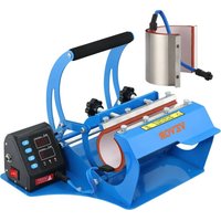
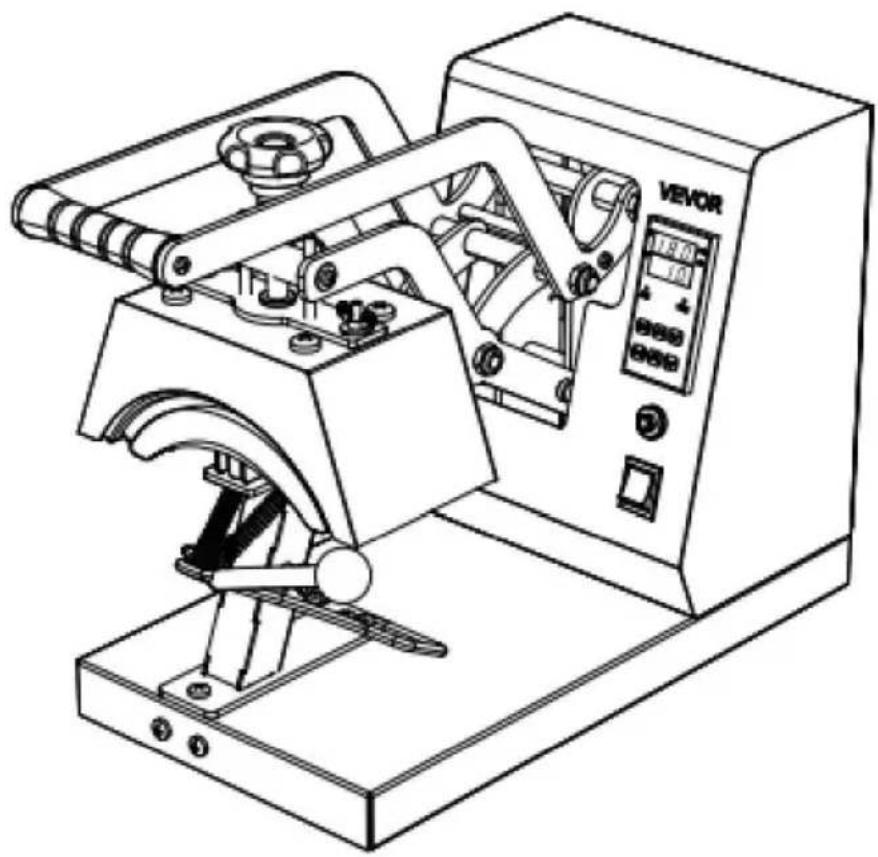
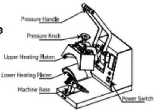
Introduction of Heat Press Machine 04
Internal Parts 04
Assembly and Disassembly of the Machine 05
Switch Between Fahrenheit and Celsius 05
Operation of the Device 06
Accessory Replacement 07
Application Range 08
Analysis of Common Faults 09
SAFETY INSTRUCTION
When using electrical appliances, basic safety precautions should always be followed including the following:

Warning-To reduce the risk of injury, user must read instructions manual
carefully and save these instruction.
 | This symbol, placed before a safety comment, indicates a kind of precaution, warning, or danger. Ignoring this warning may lead to an accident. To reduce the risk of injury, fire, or electrocution, please always follow the recommendation shown below. |
 | This product is subject to the provision of European Directive 2012/19/EC. The symbol showing a wheelie bin crossed through indicates that the product requires separate refuse collection in the European Union. This applies to the product and all accessories marked with this symbol. Products marked as such may not be discarded with normal domestic waste, but must be taken to a collection point for recycling electrical and electronic devices |
 | This device complies with Part 15 of the FCC Rules.Operation is subject to the following two conditions:(1)This device may not cause harmful interference, and (2)this device must accept any interference received,including interference that may cause undesired operation. |

Warning:
- Warnings must be followed carefully to avoid body injury, Improper-use may result in electric shock, fire, personal injury and other damage;
1) Keep unplug when moving the machine.
2) keep unplug when installing accessories.
3) Place on a flat and stable platform and operate under ventilated conditions.
4) Wear special protective equipment when operating the machine
5) Do not use this machine in a hazardous-location.
6) Do not use when the machine is not working properly.
7) Do not disassembly and repair this machine.
8) Do not use an unsuitable AC outlet.
9) Do not touch the heating plate when the machine heating
10) Do not use in humid environment or contact with water. Do not infiltrate liquid in the machine to prevent fire or electric shock caused by short circuit.
11) Do not use the power supply that does not meet the rated voltage, The power supply that does not meet the specified voltage may cause fire or electric shock.
12) Ensure that the machine is grounded so as not to cause harm to body.
13) Do not touch the rotating rod or bearing part with your fingers during use in case of injuries.
14) If the machine is not in use for a long time, please unplug the power cord from the socket.
15) Do not use the machine during thunderstorms or lighting to avoid damage to the machine.
16) Place the machine smoothly on the flame-retardant table and keep away from inflammable and explosive items.
17) If the machine smokes, emits peculiar smell, becomes noisy and other abnormal conditions, please stop using.
18) This appliance can be used by children aged from 8 years and above and persons with reduced physical, sensory or mental capabilities or lack of experience and knowledge if they have been given supervision or instruction concerning use of the appliance in a safe way and understand the hazards involved. Children shall not play with the appliance. Cleaning and user maintenance shall not be made by children without supervision
2, Type Y attachment: If the supply cord is damaged, it must be replaced by the manufacturer, its service agent or similarly qualified persons in order to avoid a hazard.
3, In order to avoid a hazard due to inadvertent resetting of the thermal cutout, this appliance must not be supplied through an external switching device, such as a timer, or connected to a circuit that is regularly switched on and off by the utility.
INTRODUCTION OF HEAT PRESS MACHINE
| Mode | TLM2310-4S |
| Temperature Range | 0-570°F/0-299°C |
| Timer Range | 0-999s |
| Rated voltage/frequency | 120V~ 50/60Hz 580W For US users |
| 220-240V~ 50/60Hz 555W For European users | |
| Package Size | 22×12.2×16 in / 56×31×40.5 cm |
| Product Weight | GW 13.7kg 30.2lbs | NW 12.3kg 27.1 lbs |

natural_image
Technical line drawing of a mechanical device with no visible text or symbols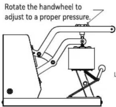
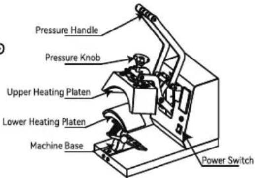
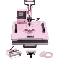
INTERNAL PARTS
A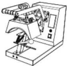 | B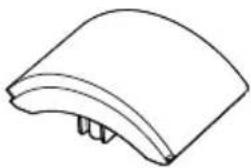 170x98mm (6.7x3.86 in) 170x98mm (6.7x3.86 in) | C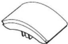 151x76mm (6x3 in) 151x76mm (6x3 in) |
D 170x69mm (6.7x2.7 in) 170x69mm (6.7x2.7 in) | E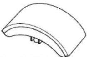 206x90mm (8.1x3.5 in) 206x90mm (8.1x3.5 in) | F Instruction manual Instruction manual |
Note: The cap press base has been installed in Machine A before delivery.
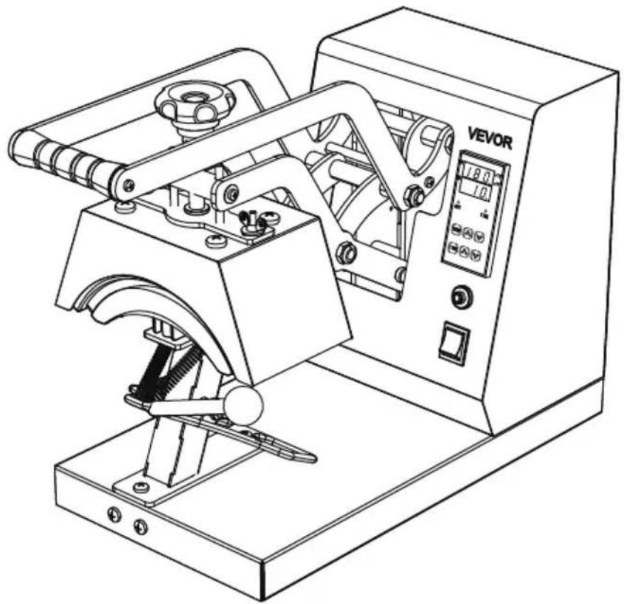
ASSEMBLY AND DISASSEMBLY OF THE MACHINE
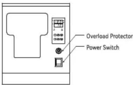
a. Connect the power supply
- Connect the plug to the power supply according to the voltage marked on the equipment package. Turn on the main switch and the power indicator lights up.
Type Y Connection :
If the power cable is damaged, it must be replaced by the manufacturer, service agency or a similarly qualified organization to avoid danger.
b.Parameter Setting
Temperature setting: On the initial state, click the “TEMP” key, and the temperature indicator starts to blink. Press the “A” or “V” key to set the required working temperature, and click the “TEMP” key to return to the initial screen.
TIME setting: Click the “TIME” key on the initial interface, and the indicator will blink. Press the “☐” or “☐” key to set the required working time, and click the “TIME” key to return to the initial interface.
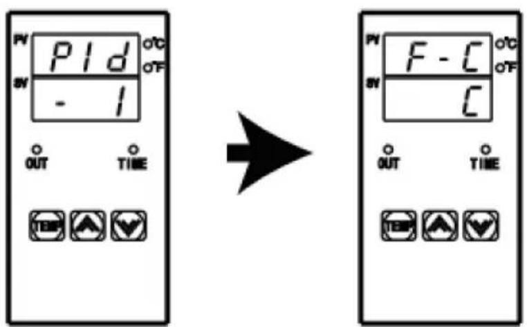
SWITCHING BETWEEN CELSIUS AND FAHRENHEIT
Long press the “☐” and “☑” key for 4 seconds at the same time to appear the interface as shown in the left picture, then click the “TEMP” key to appear the interface as shown in the second picture, then click “☐” to switch to Fahrenheit, and click “☑” to switch to Celsius. Finally, double-click “TEMP” to exit the setting mode and return to the initial state.
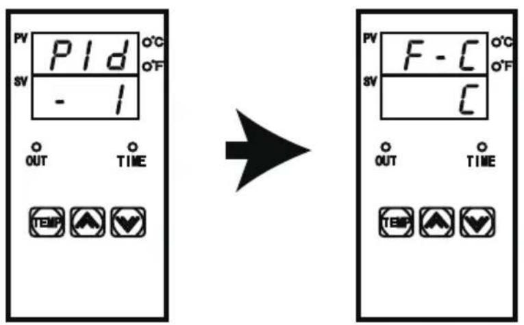
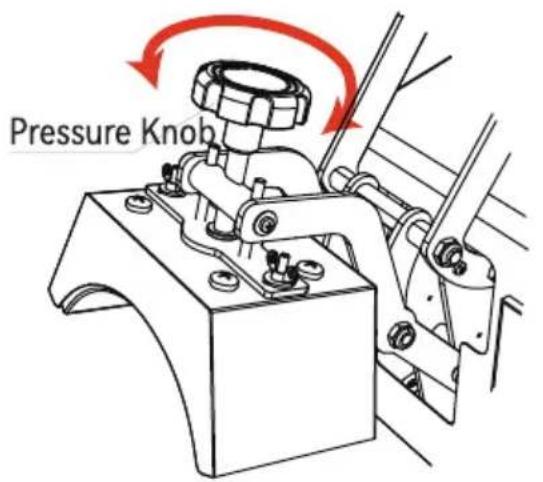
Fig 1
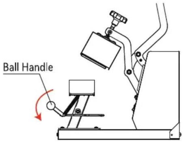
Fig 2
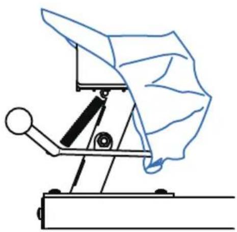
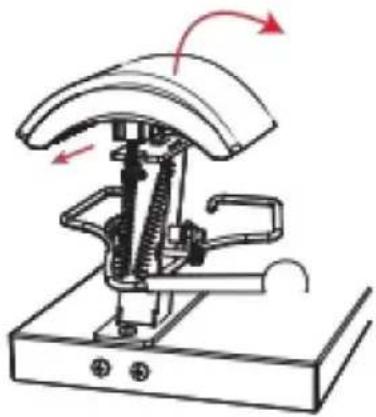
- Adjust the knob to the appropriate pressure. Turning the knob clockwise can increase the pressure of the equipment; Turning the knob counterclockwise can reduce the pressure of the device to the appropriate pressure.
- Press down the ball handle to open the cap press.
natural_image
Simple line drawing of a mechanical device with a cloth-like cover and lever mechanism (no text or symbols)Fig 3
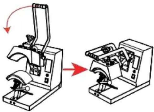
natural_image
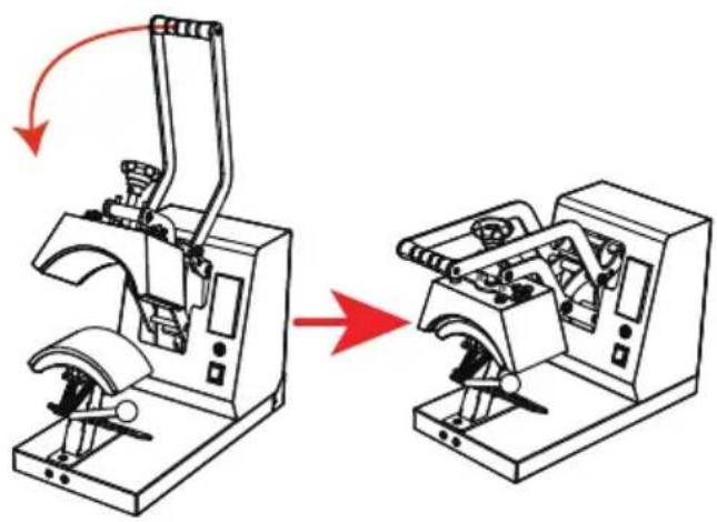
Diagram showing a mechanical device before and after assembly, with no visible text or symbolsFig 4
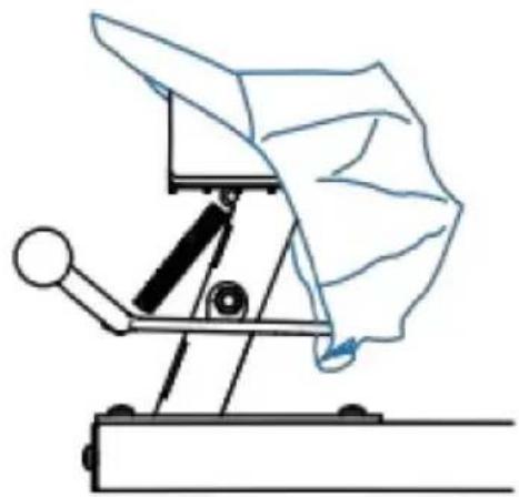
- Place the hat flat on the cap press, press down on the handle, and use the cap holder to smooth and fix the hat.
- When the machine reaches the set temperature, press the handle down to the bottom, and the timer will start counting. When the countdown is over, the machine will emit a beeping sound of "drip, drip, drip", at this time, lift the handle to complete the work.
ACCESSORY REPLACEMENT
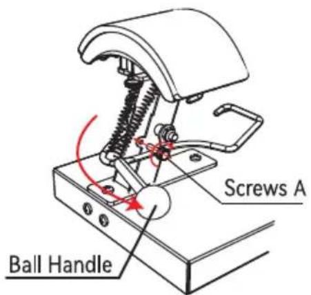
Fig 1
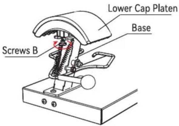
Fig 2
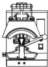
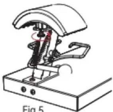
- Press down the Ball Handle and lock Screws A clockwise into the limit hole.
- Turn Screws B clockwise about 5-7 turns to loosen the Lower Cap Platen from the Base.
natural_image
Mechanical device diagram showing a press or actuator mechanism with red arrows indicating motion (no text or symbols present)Fig 3
natural_image
Mechanical device diagram showing a press or clamping mechanism with no visible text or symbolsFig 4
- Disconnect the Lower Cap Platen forward, and then remove this accessory upward.
- Install the Lower Cap Platen to be installed in Base from top to bottom and push back 1cm to snap into Mount.
natural_image
Technical line drawing of a mechanical device with spring and lever mechanism (no text or symbols)Fig 5
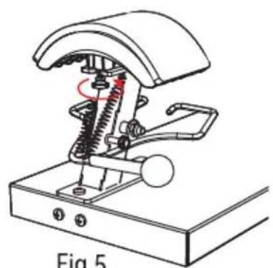
- Turn counterclockwise to lock Screws B.
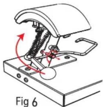
- With Screws A out of the restriction hole counterclockwise, lift up the Ball Handle and the accessory replacement is completed.
APPLICATION RANGE
| Example |  |  |  |
| Consumables | Dye Sublimation Paper | HTV | Vinyl |
| Temp | 180°C/356°F | 180°C/356°F | 170°C/338°F |
| Time | 60s | 7s | 15s |
| Common Faults | Fault Causes | Solution | |
| 1 | Unable to heat, but display works. | The heating platen or relay is damaged. | Contact the after-sales service to check whether the heating plate or relay is damaged. |
| 2 | Light color or faded image. | Insufficient heating time or temperature. | Adjust the temperature and/or increase the heating time. |
| 3 | Dark color or Fuzzy image. | Pressing time is too long or temperature is too high. | Adjust heating temperature and time. |
| 4 | Does not work after startup. | Whether the plug is in good contact. | Check that the plug is in good contact. |
| Whether the fuse is fused. | Check whether the fuse is fused. | ||
| 5 | The actual temperature exceeds the setting temperature. | Relay is disconnected. | Contact the after-sales service to replace the relay. |
VEVOR®
TOUGH TOOLS, HALF PRICE
Technical Support and E-Warranty Certificate
www.vevor.com/support
VEVOR®
TOUGH TOOLS, HALF PRICE
Technical Support and E-Warranty Certificate www.vevor.com/support
MACCHINA PER PRESSA A CALDO MANUALE D'USO
We continue to be committed to provide you tools with competitive price. "Save Half", "Half Price" or any other similar expressions used by us only represents an estimate of savings you might benefit from buying certain tools with us compared to the major top brands and does not necessarily mean to cover all categories of tools offered by us. You are kindly reminded to verify carefully when you are placing an order with us if you are actually saving half in comparison with the top major brands.
VEVOR®
HEAT PRESS MACHINE
USER MANUAL
TLM2310-4S
natural_image
Technical line drawing of a Vevor industrial machine with no visible text or symbolsNEED HELP? CONTACT US!
Have product questions? Need technical support? Please feel free to contact us:
elettronica www.vevor.com/support
This is the original instruction, please read all manual instructions carefully before operating. VEVOR reserves clear interpretation of our user manual. The appearance of the product shall be subject to the product you received. Please forgive us that we won't inform you again if there is any technology or software updates on our product.
CONTENUTO
natural_image
Pure mechanical diagram of a device without any text, numbers, or symbols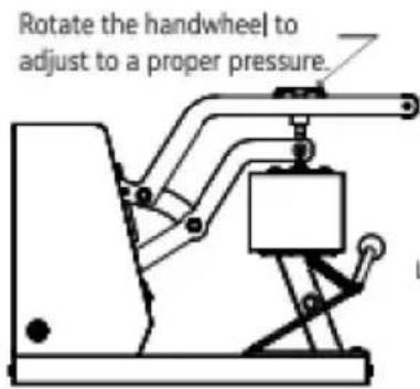
INTERNAL PARTS
A | B 170x98mm (6.7x3.86 in) 170x98mm (6.7x3.86 in) | C 151x76mm (6x3 in) 151x76mm (6x3 in) |
D 170x59mm (6.7x2.7 in) 170x59mm (6.7x2.7 in) | E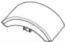 206x90mm (8.1x3.5 in) 206x90mm (8.1x3.5 in) | F Instruction manual Instruction manual |
Note: The cap press base has been installed in Machine A before delivery.
ASSEMBLY AND DISASSEMBLY OF THE MACHINE
a. Connect the power supply
- Connect the plug to the power supply according to the voltage marked on the equipment package. Turn on the main switch and the power indicator lights up.
Type Y Connection :
If the power cable is damaged, it must be replaced by the manufacturer, service agency or a similarly qualified organization to avoid danger.
b.Parameter Setting
Temperature setting: On the initial state, click the “TEMP” key, and the temperature indicator starts to blink. Press the “A” or “V” key to set the required working temperature, and click the “TEMP” key to return to the initial screen.
TIME setting: Click the “TIME” key on the initial interface, and the indicator will blink. Press the “A” or “V” key to set the required working time, and click the “TIME” key to return to the initial interface.
SWITCHING BETWEEN CELSIUS AND FAHRENHEIT
Long press the “☐” and “☑” key for 4 seconds at the same time to appear the interface as shown in the left picture, then click the “TEMP” key to appear the interface as shown in the second picture, then click “☐” to switch to Fahrenheit, and click “☑” to switch to Celsius. Finally, double-click “TEMP” to exit the setting mode and return to the initial state.

ADJUSTMENT AND USE OF EQUIPMENT

Fig 1

Fig 2
- Adjust the knob to the appropriate pressure. Turning the knob clockwise can increase the pressure of the equipment; Turning the knob counterclockwise can reduce the pressure of the device to the appropriate pressure.
- Press down the ball handle to open the cap press.

natural_image
Simple line drawing of a mechanical device with a cloth-like cover and lever mechanism (no text or symbols)Fig 3
natural_image
Diagram showing a mechanical device before and after assembly, with no visible text or symbolsFig 4
- Place the hat flat on the cap press, press down on the handle, and use the cap holder to smooth and fix the hat.
- When the machine reaches the set temperature, press the handle down to the bottom, and the timer will start counting. When the countdown is over, the machine will emit a beeping sound of "drip, drip, drip", at this time, lift the handle to complete the work.
ACCESSORY REPLACEMENT

Fig 1

Fig 2
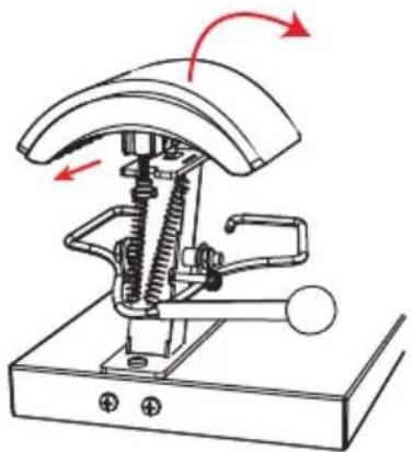
- Press down the Ball Handle and lock Screws A clockwise into the limit hole.
- Turn Screws B clockwise about 5-7 turns to loosen the Lower Cap Platen from the Base.

natural_image
Mechanical device with rotating arm and base mount (no text or symbols)Fig 3

natural_image
Mechanical device with curved top and base, showing internal components and directional arrows (no text or symbols)Fig 4
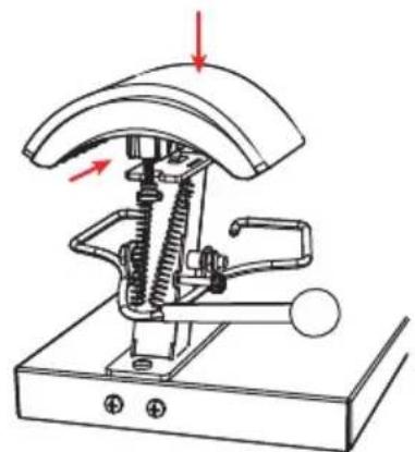
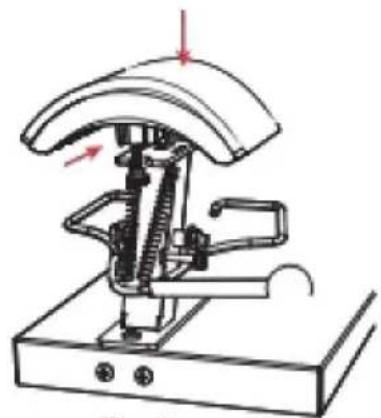
- Disconnect the Lower Cap Platen forward, and then remove this accessory upward.
- Install the Lower Cap Platen to be installed in Base from top to bottom and push back 1cm to snap into Mount.

natural_image
Technical line drawing of a mechanical device with no visible text or symbolsFig 5

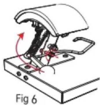
natural_image
Diagram of a mechanical device with rotating arm and base, labeled Fig 6 (no text or symbols on diagram itself)- Turn counterclockwise to lock Screws B.
- With Screws A out of the restriction hole counterclockwise, lift up the Ball Handle and the accessory replacement is completed.
Technical Support and E-Warranty Certificate
www.vevor.com/support
VEVOR®
TOUGH TOOLS, HALF PRICE
Technical Support and E-Warranty Certificate www.vevor.com/support
MASZYNA DO PRASY TERMICZNEJ INSTRUKCJA OBSŁUGI
We continue to be committed to provide you tools with competitive price. "Save Half", "Half Price" or any other similar expressions used by us only represents an estimate of savings you might benefit from buying certain tools with us compared to the major top brands and does not necessarily mean to cover all categories of tools offered by us. You are kindly reminded to verify carefully when you are placing an order with us if you are actually saving half in comparison with the top major brands.
VEVOR®
HEAT PRESS MACHINE
USER MANUAL
TLM2310-4S

natural_image
Technical line drawing of a Vevor industrial machine with no visible text or symbolsNEED HELP? CONTACT US!
Have product questions? Need technical support? Please feel free to contact us:
This is the original instruction, please read all manual instructions carefully before operating. VEVOR reserves clear interpretation of our user manual. The appearance of the product shall be subject to the product you received. Please forgive us that we won't inform you again if there is any technology or software updates on our product.
ZAWARTOŚĆ
natural_image
Pure mechanical diagram of a device without any text, numbers, or symbols

INTERNAL PARTS
| A | B170x98mm (6.7x3.86 in) | C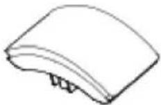 151x76mm (6x3 in) 151x76mm (6x3 in) |
| D170x59mm (6.7x2.7 in) | E206x90mm (8.1x3.5 in) | FInstruction manual |
Note: The cap press base has been installed in Machine A before delivery.
ASSEMBLY AND DISASSEMBLY OF THE MACHINE
a. Connect the power supply
- Connect the plug to the power supply according to the voltage marked on the equipment package. Turn on the main switch and the power indicator lights up.
Type Y Connection :
If the power cable is damaged, it must be replaced by the manufacturer, service agency or a similarly qualified organization to avoid danger.
b.Parameter Setting
Temperature setting: On the initial state, click the “TEMP” key, and the temperature indicator starts to blink. Press the “A” or “V” key to set the required working temperature, and click the “TEMP” key to return to the initial screen.
TIME setting: Click the “TIME” key on the initial interface, and the indicator will blink. Press the “A” or “V” key to set the required working time, and click the “TIME” key to return to the initial interface.
SWITCHING BETWEEN CELSIUS AND FAHRENHEIT
Long press the “☐” and “☑” key for 4 seconds at the same time to appear the interface as shown in the left picture, then click the “TEMP” key to appear the interface as shown in the second picture, then click “☐” to switch to Fahrenheit, and click “☑” to switch to Celsius. Finally, double-click “TEMP” to exit the setting mode and return to the initial state.

ADJUSTMENT AND USE OF EQUIPMENT

Fig 1
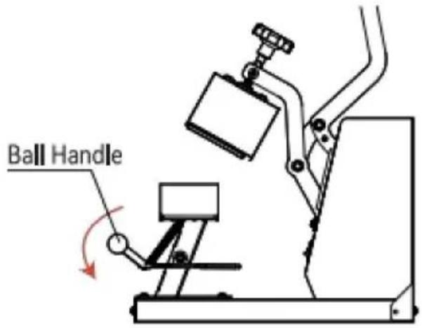
Fig 2
- Adjust the knob to the appropriate pressure. Turning the knob clockwise can increase the pressure of the equipment; Turning the knob counterclockwise can reduce the pressure of the device to the appropriate pressure.
- Press down the ball handle to open the cap press.

natural_image
Simple line drawing of a mechanical device with a cloth-like cover and lever mechanism (no text or symbols)Fig 3

natural_image
Diagram showing a mechanical device before and after assembly, with no visible text or symbolsFig 4
- Place the hat flat on the cap press, press down on the handle, and use the cap holder to smooth and fix the hat.
- When the machine reaches the set temperature, press the handle down to the bottom, and the timer will start counting. When the countdown is over, the machine will emit a beeping sound of "drip, drip, drip", at this time, lift the handle to complete the work.
ACCESSORY REPLACEMENT

Fig 1

Fig 2
- Press down the Ball Handle and lock Screws A clockwise into the limit hole.
- Turn Screws B clockwise about 5-7 turns to loosen the Lower Cap Platen from the Base.
natural_image
Mechanical device with rotating arm and base mount (no text or symbols)Fig 3

natural_image
Mechanical device with curved top and base components, no visible text or symbolsFig 4
- Disconnect the Lower Cap Platen forward, and then remove this accessory upward.
- Install the Lower Cap Platen to be installed in Base from top to bottom and push back 1cm to snap into Mount.
natural_image
Technical line drawing of a mechanical device with no visible text or symbolsFig 5

natural_image
Diagram of a mechanical device with rotating arm and base, labeled Fig 6 (no text or symbols on diagram itself)- Turn counterclockwise to lock Screws B.
- With Screws A out of the restriction hole counterclockwise, lift up the Ball Handle and the accessory replacement is completed.
ZAKRES ZASTOSOWANIA
Technical Support and E-Warranty Certificate
www.vevor.com/support
VEVOR®
TOUGH TOOLS, HALF PRICE
Technical Support and E-Warranty Certificate www.vevor.com/support
Wärmepressmaschine BENUTZERHANDBUCH
We continue to be committed to provide you tools with competitive price. "Save Half", "Half Price" or any other similar expressions used by us only represents an estimate of savings you might benefit from buying certain tools with us compared to the major top brands and does not necessarily mean to cover all categories of tools offered by us. You are kindly reminded to verify carefully when you are placing an order with us if you are actually saving half in comparison with the top major brands.
VEVOR®
HEAT PRESS MACHINE
USER MANUAL
TLM2310-4S

natural_image
Technical line drawing of a Vevor industrial machine with no visible text or symbolsNEED HELP? CONTACT US!
Have product questions? Need technical support? Please feel free to contact us:
www.vevor.com/support
This is the original instruction, please read all manual instructions carefully before operating. VEVOR reserves clear interpretation of our user manual. The appearance of the product shall be subject to the product you received. Please forgive us that we won't inform you again if there is any technology or software updates on our product.
INHALT
natural_image
Pure mechanical diagram of a device without any text, numbers, or symbols

INTERNAL PARTS
| A | B170x98mm (6.7x3.86 in) | C151x76mm (6x3 in) |
| D170x59mm (6.7x2.7 in) | E206x90mm (8.1x3.5 in) | FInstruction manual |
Note: The cap press base has been installed in Machine A before delivery.
ASSEMBLY AND DISASSEMBLY OF THE MACHINE
a. Connect the power supply
- Connect the plug to the power supply according to the voltage marked on the equipment package. Turn on the main switch and the power indicator lights up.
Type Y Connection :
If the power cable is damaged, it must be replaced by the manufacturer, service agency or a similarly qualified organization to avoid danger.
b.Parameter Setting
Temperature setting: On the initial state, click the “TEMP” key, and the temperature indicator starts to blink. Press the “A” or “V” key to set the required working temperature, and click the “TEMP” key to return to the initial screen.
TIME setting: Click the “TIME” key on the initial interface, and the indicator will blink. Press the “A” or “V” key to set the required working time, and click the “TIME” key to return to the initial interface.
SWITCHING BETWEEN CELSIUS AND FAHRENHEIT
Long press the “☐” and “☑” key for 4 seconds at the same time to appear the interface as shown in the left picture, then click the “TEMP” key to appear the interface as shown in the second picture, then click “☐” to switch to Fahrenheit, and click “☑” to switch to Celsius. Finally, double-click “TEMP” to exit the setting mode and return to the initial state.

ADJUSTMENT AND USE OF EQUIPMENT

Fig 1

Fig 2
- Adjust the knob to the appropriate pressure. Turning the knob clockwise can increase the pressure of the equipment; Turning the knob counterclockwise can reduce the pressure of the device to the appropriate pressure.
- Press down the ball handle to open the cap press.

natural_image
Simple line drawing of a mechanical device with a cloth-like cover and lever mechanism (no text or symbols)Fig 3

natural_image
Diagram showing a mechanical device before and after assembly, with no visible text or symbolsFig 4
- Place the hat flat on the cap press, press down on the handle, and use the cap holder to smooth and fix the hat.
- When the machine reaches the set temperature, press the handle down to the bottom, and the timer will start counting. When the countdown is over, the machine will emit a beeping sound of "drip, drip, drip", at this time, lift the handle to complete the work.
ACCESSORY REPLACEMENT

Fig 1

Fig 2
- Press down the Ball Handle and lock Screws A clockwise into the limit hole.
- Turn Screws B clockwise about 5-7 turns to loosen the Lower Cap Platen from the Base.

natural_image
Mechanical device with rotating arm and base mount (no text or symbols)Fig 3

natural_image
Mechanical device with curved top and base components, no visible text or symbolsFig 4
- Disconnect the Lower Cap Platen forward, and then remove this accessory upward.
- Install the Lower Cap Platen to be installed in Base from top to bottom and push back 1cm to snap into Mount.

natural_image
Technical line drawing of a mechanical device with no visible text or symbolsFig 5

natural_image
Diagram of a mechanical device with rotating arm and base, labeled Fig 6 (no text or symbols on diagram itself)- Turn counterclockwise to lock Screws B.
- With Screws A out of the restriction hole counterclockwise, lift up the Ball Handle and the accessory replacement is completed.
ANWENDUNGSBEREICH
Technical Support and E-Warranty Certificate
www.vevor.com/support
VEVOR®
TOUGH TOOLS, HALF PRICE
Technical Support and E-Warranty Certificate www.vevor.com/support
PRESSE A CHAUD
MANUEL D'UTILISATION
We continue to be committed to provide you tools with competitive price. "Save Half", "Half Price" or any other similar expressions used by us only represents an estimate of savings you might benefit from buying certain tools with us compared to the major top brands and does not necessarily mean to cover all categories of tools offered by us. You are kindly reminded to verify carefully when you are placing an order with us if you are actually saving half in comparison with the top major brands.
VEVOR®
HEAT PRESS MACHINE
USER MANUAL
TLM2310-4S

natural_image
Technical line drawing of a Vevor industrial machine with no visible text or symbolsNEED HELP? CONTACT US!
Have product questions? Need technical support? Please feel free to contact us:
This is the original instruction, please read all manual instructions carefully before operating. VEVOR reserves clear interpretation of our user manual. The appearance of the product shall be subject to the product you received. Please forgive us that we won't inform you again if there is any technology or software updates on our product.
CONTENU
natural_image
Pure mechanical diagram of a device without any text, numbers, or symbols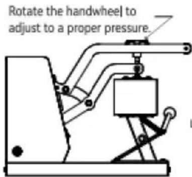

INTERNAL PARTS
| A | B170x98mm (6.7x3.86 in) | C151x76mm (6x3 in) |
| D170x59mm (6.7x2.7 in) | E206x90mm (8.1x3.5 in) | FInstruction manual |
Note: The cap press base has been installed in Machine A before delivery.
ASSEMBLY AND DISASSEMBLY OF THE MACHINE
a. Connect the power supply
- Connect the plug to the power supply according to the voltage marked on the equipment package. Turn on the main switch and the power indicator lights up.
Type Y Connection :
If the power cable is damaged, it must be replaced by the manufacturer, service agency or a similarly qualified organization to avoid danger.
b.Parameter Setting
Temperature setting: On the initial state, click the “TEMP” key, and the temperature indicator starts to blink. Press the “A” or “V” key to set the required working temperature, and click the “TEMP” key to return to the initial screen.
TIME setting: Click the “TIME” key on the initial interface, and the indicator will blink. Press the “A” or “V” key to set the required working time, and click the “TIME” key to return to the initial interface.
SWITCHING BETWEEN CELSIUS AND FAHRENHEIT
Long press the “☐” and “☑” key for 4 seconds at the same time to appear the interface as shown in the left picture, then click the “TEMP” key to appear the interface as shown in the second picture, then click “☐” to switch to Fahrenheit, and click “☑” to switch to Celsius. Finally, double-click “TEMP” to exit the setting mode and return to the initial state.

ADJUSTMENT AND USE OF EQUIPMENT

Fig 1

Fig 2
- Adjust the knob to the appropriate pressure. Turning the knob clockwise can increase the pressure of the equipment; Turning the knob counterclockwise can reduce the pressure of the device to the appropriate pressure.
- Press down the ball handle to open the cap press.

natural_image
Simple line drawing of a mechanical device with a cloth-like cover and lever mechanism (no text or symbols)Fig 3

natural_image
Diagram showing a mechanical device before and after assembly, with no visible text or symbolsFig 4
- Place the hat flat on the cap press, press down on the handle, and use the cap holder to smooth and fix the hat.
- When the machine reaches the set temperature, press the handle down to the bottom, and the timer will start counting. When the countdown is over, the machine will emit a beeping sound of "drip, drip, drip", at this time, lift the handle to complete the work.
ACCESSORY REPLACEMENT

Fig 1
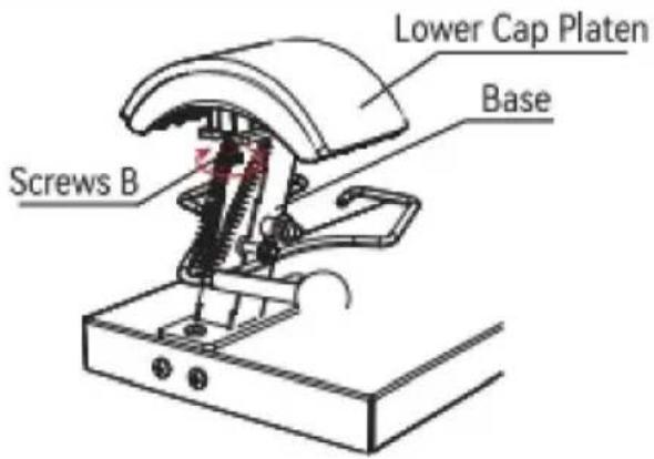
Fig 2
- Press down the Ball Handle and lock Screws A clockwise into the limit hole.
- Turn Screws B clockwise about 5-7 turns to loosen the Lower Cap Platen from the Base.

natural_image
Mechanical device with rotating arm and base mount (no text or symbols)Fig 3

natural_image
Mechanical device with curved top and base components, no visible text or symbolsFig 4
- Disconnect the Lower Cap Platen forward, and then remove this accessory upward.
- Install the Lower Cap Platen to be installed in Base from top to bottom and push back 1cm to snap into Mount.

natural_image
Technical line drawing of a mechanical device with no visible text or symbolsFig 5

natural_image
Diagram of a mechanical device with rotating arm and base, labeled Fig 6 (no text or symbols on diagram itself)- Turn counterclockwise to lock Screws B.
- With Screws A out of the restriction hole counterclockwise, lift up the Ball Handle and the accessory replacement is completed.
DOMAINE D'APPLICATION
| Exemple |  |  |  |
| consommables | Dye Sublimation Paper | HTV | vinyle |
| Température | 170 /338F180 /356F180 /356F | ||
| Temps | ### | 7S | 15S |
ANALYSE DES DÉFAUTS COURANTS
Technical Support and E-Warranty Certificate
www.vevor.com/support
VEVOR®
TOUGH TOOLS, HALF PRICE
Technical Support and E-Warranty Certificate www.vevor.com/support
WARMTEPERSMACHINE
GEBRUIKERSHANDLEIDING
We continue to be committed to provide you tools with competitive price. "Save Half", "Half Price" or any other similar expressions used by us only represents an estimate of savings you might benefit from buying certain tools with us compared to the major top brands and does not necessarily mean to cover all categories of tools offered by us. You are kindly reminded to verify carefully when you are placing an order with us if you are actually saving half in comparison with the top major brands.
VEVOR®
HEAT PRESS MACHINE
USER MANUAL
TLM2310-4S

natural_image
Technical line drawing of a Vevor industrial machine with no visible text or symbolsNEED HELP? CONTACT US!
Have product questions? Need technical support? Please feel free to contact us:
www.vevor.com/support
This is the original instruction, please read all manual instructions carefully before operating. VEVOR reserves clear interpretation of our user manual. The appearance of the product shall be subject to the product you received. Please forgive us that we won't inform you again if there is any technology or software updates on our product.
INHOUD
natural_image
Pure mechanical diagram of a device without any text, numbers, or symbols

INTERNAL PARTS
| A | B170x98mm (6.7x3.86 in) | C151x76mm (6x3 in) |
| D170x59mm (6.7x2.7 in) | E206x90mm (8.1x3.5 in) | FInstruction manual |
Note: The cap press base has been installed in Machine A before delivery.
ASSEMBLY AND DISASSEMBLY OF THE MACHINE
a. Connect the power supply
- Connect the plug to the power supply according to the voltage marked on the equipment package. Turn on the main switch and the power indicator lights up.
Type Y Connection :
If the power cable is damaged, it must be replaced by the manufacturer, service agency or a similarly qualified organization to avoid danger.
b.Parameter Setting
Temperature setting: On the initial state, click the “TEMP” key, and the temperature indicator starts to blink. Press the “A” or “V” key to set the required working temperature, and click the “TEMP” key to return to the initial screen.
TIME setting: Click the “TIME” key on the initial interface, and the indicator will blink. Press the “A” or “V” key to set the required working time, and click the “TIME” key to return to the initial interface.
SWITCHING BETWEEN CELSIUS AND FAHRENHEIT
Long press the “☐” and “☑” key for 4 seconds at the same time to appear the interface as shown in the left picture, then click the “TEMP” key to appear the interface as shown in the second picture, then click “☐” to switch to Fahrenheit, and click “☑” to switch to Celsius. Finally, double-click “TEMP” to exit the setting mode and return to the initial state.
ADJUSTMENT AND USE OF EQUIPMENT

Fig 1

Fig 2
- Adjust the knob to the appropriate pressure. Turning the knob clockwise can increase the pressure of the equipment; Turning the knob counterclockwise can reduce the pressure of the device to the appropriate pressure.
- Press down the ball handle to open the cap press.

natural_image
Simple line drawing of a mechanical device with a cloth-like cover and lever mechanism (no text or symbols)Fig 3

natural_image
Diagram showing a mechanical device before and after assembly, with no visible text or symbolsFig 4
- Place the hat flat on the cap press, press down on the handle, and use the cap holder to smooth and fix the hat.
- When the machine reaches the set temperature, press the handle down to the bottom, and the timer will start counting. When the countdown is over, the machine will emit a beeping sound of "drip, drip, drip", at this time, lift the handle to complete the work.
ACCESSORY REPLACEMENT

Fig 1

Fig 2
- Press down the Ball Handle and lock Screws A clockwise into the limit hole.
- Turn Screws B clockwise about 5-7 turns to loosen the Lower Cap Platen from the Base.

natural_image
Mechanical device with rotating arm and base mount (no text or symbols)Fig 3

natural_image
Mechanical device with curved top and base, showing internal components and directional arrows (no text or symbols)Fig 4
- Disconnect the Lower Cap Platen forward, and then remove this accessory upward.
- Install the Lower Cap Platen to be installed in Base from top to bottom and push back 1cm to snap into Mount.

natural_image
Technical line drawing of a mechanical device with no visible text or symbolsFig 5

natural_image
Diagram of a mechanical device with rotating arm and base, labeled Fig 6 (no text or symbols on diagram itself)- Turn counterclockwise to lock Screws B.
- With Screws A out of the restriction hole counterclockwise, lift up the Ball Handle and the accessory replacement is completed.
TOEPASSINGSBEREIK
Technical Support and E-Warranty Certificate
www.vevor.com/support
VEVOR®
TOUGH TOOLS, HALF PRICE
Technical Support and E-Warranty Certificate www.vevor.com/support
VÄRMEPRESSMASKIN ANVÄNDARMANUAL
We continue to be committed to provide you tools with competitive price. "Save Half", "Half Price" or any other similar expressions used by us only represents an estimate of savings you might benefit from buying certain tools with us compared to the major top brands and does not necessarily mean to cover all categories of tools offered by us. You are kindly reminded to verify carefully when you are placing an order with us if you are actually saving half in comparison with the top major brands.
VEVOR®
HEAT PRESS MACHINE
USER MANUAL
TLM2310-4S

natural_image
Technical line drawing of a Vevor industrial machine with no visible text or symbolsNEED HELP? CONTACT US!
Have product questions? Need technical support? Please feel free to contact us:
www.vevor.com/support
This is the original instruction, please read all manual instructions carefully before operating. VEVOR reserves clear interpretation of our user manual. The appearance of the product shall be subject to the product you received. Please forgive us that we won't inform you again if there is any technology or software updates on our product.
INNEHÅLL
natural_image
Pure mechanical diagram of a device without any text, numbers, or symbols

INTERNAL PARTS
| A | B170x98mm (6.7x3.86 in) | C151x76mm (6x3 in) |
| D170x59mm (6.7x2.7 in) | E206x90mm (8.1x3.5 in) | FInstruction manual |
Note: The cap press base has been installed in Machine A before delivery.
ASSEMBLY AND DISASSEMBLY OF THE MACHINE
a. Connect the power supply
- Connect the plug to the power supply according to the voltage marked on the equipment package. Turn on the main switch and the power indicator lights up.
Type Y Connection :
If the power cable is damaged, it must be replaced by the manufacturer, service agency or a similarly qualified organization to avoid danger.
b.Parameter Setting
Temperature setting: On the initial state, click the “TEMP” key, and the temperature indicator starts to blink. Press the “A” or “V” key to set the required working temperature, and click the “TEMP” key to return to the initial screen.
TIME setting: Click the “TIME” key on the initial interface, and the indicator will blink. Press the “A” or “V” key to set the required working time, and click the “TIME” key to return to the initial interface.
SWITCHING BETWEEN CELSIUS AND FAHRENHEIT
Long press the “☐” and “☑” key for 4 seconds at the same time to appear the interface as shown in the left picture, then click the “TEMP” key to appear the interface as shown in the second picture, then click “☐” to switch to Fahrenheit, and click “☑” to switch to Celsius. Finally, double-click “TEMP” to exit the setting mode and return to the initial state.

ADJUSTMENT AND USE OF EQUIPMENT
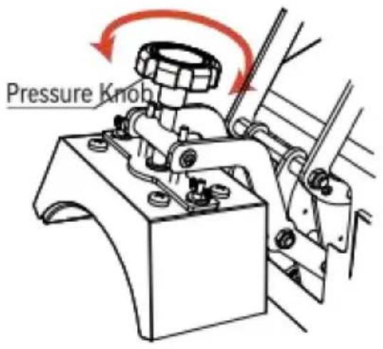
Fig 1

Fig 2
- Adjust the knob to the appropriate pressure. Turning the knob clockwise can increase the pressure of the equipment; Turning the knob counterclockwise can reduce the pressure of the device to the appropriate pressure.
- Press down the ball handle to open the cap press.
natural_image
Simple line drawing of a mechanical device with a cloth-like cover and lever mechanism (no text or symbols)Fig 3

natural_image
Diagram showing a mechanical device before and after assembly, with no visible text or symbolsFig 4
- Place the hat flat on the cap press, press down on the handle, and use the cap holder to smooth and fix the hat.
- When the machine reaches the set temperature, press the handle down to the bottom, and the timer will start counting. When the countdown is over, the machine will emit a beeping sound of "drip, drip, drip", at this time, lift the handle to complete the work.
ACCESSORY REPLACEMENT
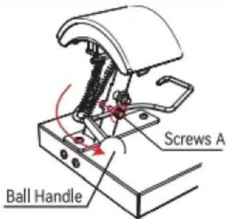
Fig 1

Fig 2
- Press down the Ball Handle and lock Screws A clockwise into the limit hole.
- Turn Screws B clockwise about 5-7 turns to loosen the Lower Cap Platen from the Base.

natural_image
Mechanical device with rotating arm and base mount (no text or symbols)Fig 3

natural_image
Mechanical device with curved top and base components, no visible text or symbolsFig 4
- Disconnect the Lower Cap Platen forward, and then remove this accessory upward.
- Install the Lower Cap Platen to be installed in Base from top to bottom and push back 1cm to snap into Mount.

natural_image
Technical line drawing of a mechanical device with no visible text or symbolsFig 5
natural_image
Diagram of a mechanical device with rotating arm and base, labeled Fig 6 (no text or symbols on diagram itself)- Turn counterclockwise to lock Screws B.
- With Screws A out of the restriction hole counterclockwise, lift up the Ball Handle and the accessory replacement is completed.
ANVÄNDNINGSOMRÅDE
| Exempel | | | |
| förbrukningsvaror | Dye Sublimation Paper | HTV | vinyl |
| Temp | 170 /338F180 /356 F180 /356 | ||
| Tid | 60S | 7S | 15S |
ANALYS AV VANLIGA FEL
Technical Support and E-Warranty Certificate
www.vevor.com/support
VEVOR®
TOUGH TOOLS, HALF PRICE
Technical Support and E-Warranty Certificate www.vevor.com/support
MÁQUINA DE PRENSA TÉRMICA MANUAL DEL USUARIO
We continue to be committed to provide you tools with competitive price. "Save Half", "Half Price" or any other similar expressions used by us only represents an estimate of savings you might benefit from buying certain tools with us compared to the major top brands and does not necessarily mean to cover all categories of tools offered by us. You are kindly reminded to verify carefully when you are placing an order with us if you are actually saving half in comparison with the top major brands.
VEVOR®
HEAT PRESS MACHINE
USER MANUAL
TLM2310-4S

natural_image
Technical line drawing of a Vevor industrial machine with no visible text or symbolsNEED HELP? CONTACT US!
Have product questions? Need technical support? Please feel free to contact us:
This is the original instruction, please read all manual instructions carefully before operating. VEVOR reserves clear interpretation of our user manual. The appearance of the product shall be subject to the product you received. Please forgive us that we won't inform you again if there is any technology or software updates on our product.
CONTENIDO
natural_image
Pure mechanical diagram of a device without any text, numbers, or symbols

INTERNAL PARTS
| A | B170x98mm (6.7x3.86 in) | C151x76mm (6x3 in) |
| D170x59mm (6.7x2.7 in) | E206x90mm (8.1x3.5 in) | FInstruction manual |
Note: The cap press base has been installed in Machine A before delivery.
ASSEMBLY AND DISASSEMBLY OF THE MACHINE
a. Connect the power supply
- Connect the plug to the power supply according to the voltage marked on the equipment package. Turn on the main switch and the power indicator lights up.
Type Y Connection :
If the power cable is damaged, it must be replaced by the manufacturer, service agency or a similarly qualified organization to avoid danger.
b.Parameter Setting
Temperature setting: On the initial state, click the “TEMP” key, and the temperature indicator starts to blink. Press the “A” or “V” key to set the required working temperature, and click the “TEMP” key to return to the initial screen.
TIME setting: Click the “TIME” key on the initial interface, and the indicator will blink. Press the “A” or “V” key to set the required working time, and click the “TIME” key to return to the initial interface.
SWITCHING BETWEEN CELSIUS AND FAHRENHEIT
Long press the “☐” and “☑” key for 4 seconds at the same time to appear the interface as shown in the left picture, then click the “TEMP” key to appear the interface as shown in the second picture, then click “☐” to switch to Fahrenheit, and click “☑” to switch to Celsius. Finally, double-click “TEMP” to exit the setting mode and return to the initial state.

ADJUSTMENT AND USE OF EQUIPMENT

Fig 1

Fig 2
- Adjust the knob to the appropriate pressure. Turning the knob clockwise can increase the pressure of the equipment; Turning the knob counterclockwise can reduce the pressure of the device to the appropriate pressure.
- Press down the ball handle to open the cap press.

natural_image
Simple line drawing of a mechanical device with a cloth-like cover and lever mechanism (no text or symbols)Fig 3

natural_image
Diagram showing a mechanical device before and after assembly, with no visible text or symbolsFig 4
- Place the hat flat on the cap press, press down on the handle, and use the cap holder to smooth and fix the hat.
- When the machine reaches the set temperature, press the handle down to the bottom, and the timer will start counting. When the countdown is over, the machine will emit a beeping sound of "drip, drip, drip", at this time, lift the handle to complete the work.
ACCESSORY REPLACEMENT

Fig 1

Fig 2
- Press down the Ball Handle and lock Screws A clockwise into the limit hole.
- Turn Screws B clockwise about 5-7 turns to loosen the Lower Cap Platen from the Base.

natural_image
Mechanical device with rotating arm and base mount (no text or symbols)Fig 3
natural_image
Mechanical device with curved top and base components, no visible text or symbolsFig 4
- Disconnect the Lower Cap Platen forward, and then remove this accessory upward.
- Install the Lower Cap Platen to be installed in Base from top to bottom and push back 1cm to snap into Mount.

natural_image
Technical line drawing of a mechanical device with no visible text or symbolsFig 5

natural_image
Diagram of a mechanical device with rotating arm and base, labeled Fig 6 (no text or symbols on diagram itself)- Turn counterclockwise to lock Screws B.
- With Screws A out of the restriction hole counterclockwise, lift up the Ball Handle and the accessory replacement is completed.
RANGO DE APLICACIÓN
| Ejemplo | |  |  |
| consumibles | Dye Sublimation Paper | vinilo | |
| Temperatura | 180 /356 F 170 | 338 F180 /356 F | |
| Tiempo | Años 60 | 7S | 15S |
ANÁLISIS DE FALLAS COMUNES
Technical Support and E-Warranty Certificate
www.vevor.com/support