WL1000GV - Wood lathe Vevor - Free user manual and instructions
Find the device manual for free WL1000GV Vevor in PDF.

| Product type | Wood lathe |
| Brand | Vevor |
| Model | WL1000GV |
| Package dimensions (L×W×H) | 1490 × 410 × 572 mm |
| Net / gross weight | 63 kg / 83.76 kg |
| Power supply | 230 V / 50 Hz or 110 V / 60 Hz |
| Motor power | 750 W |
| Spindle speed range (50 Hz) | 680 – 2,520 rpm ± 10% |
| Spindle speed range (60 Hz) | 700 – 2,600 rpm ± 10% |
| Max. turning diameter | ∅ 350 mm |
| Distance between centers | 960 mm |
| Spindle taper / tailstock taper | MT1 / MT1 |
| Spindle thread | M18 |
| Tailstock travel | 80 mm |
| Main functions | Wood turning, copying with template, continuous speed variation, digital display, work light |
| Safety | On/off switch, recommended hearing and eye protection, mandatory grounding, emergency stop |
| Maintenance | Lubrication every 100 h, cleaning after each use, belt check at 50 h |
| Spare parts | Full list provided in manual, including spindle, pulleys, bearings, tool rest |
| Warranty | 1 year (excluding misuse) |
| Certifications | FCC (Part 15), WEEE directive (2012/19/EU) |
Frequently Asked Questions - WL1000GV Vevor
User questions about WL1000GV Vevor
0 question about this device. Answer the ones you know or ask your own.
Ask a new question about this device
Download the instructions for your Wood lathe in PDF format for free! Find your manual WL1000GV - Vevor and take your electronic device back in hand. On this page are published all the documents necessary for the use of your device. WL1000GV by Vevor.
USER MANUAL WL1000GV Vevor
Technical Support and E-Warranty Certificate www.vevor.com/support
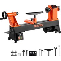
WOOD LATHE
INSTRUCTION MANUAL
MODEL: WL-1000GV
We continue to be committed to provide you tools with competitive price. "Save Half", "Half Price" or any other similar expressions used by us only repressor estimate of savings you might benefit from buying certain tools with us compared to top brands and does not necessarily mean to cover all categories of tools offered by are kindly reminded to verify carefully when you are placing an order with us if yo actually saving half in comparison with the top major brands.
VEVOR®
TOUGH TOOLS, HALF PRICE
WOOD LATHE
MODEL:WL-1000GV

natural_image
Industrial machine with adjustable arms and a black base plate (no visible text or symbols)NEED HELP? CONTACT US!
Have product questions? Need technical support? Please feel free contact us:
Technical Support and E-Warranty Certificate www.vevor.com/support
This is the original instruction, please read all manual instructions carefully before operating. VEVOR reserves a clear interpretation of user manual. The appearance of the product shall be subject to the product you received. Please forgive us that we won't inform you there are any technology or software updates on our product.
The information contained in this handbook is intended as a guide to the operation of these machines and does not form part of any contract. The data it contains has been obtained from the machine manufacturer and from other sources. We strive to ensure the accuracy of this information and try to verify each item and each data, but we cannot guarantee the accuracy of the information, which means that the equipment supply may differ in detail from the description of the instructions. Furthermore, development of the machine may mean that the equipment supplied may differ in detail from the descriptions herein. The responsibility therefore lie with the user to satisfy himself that the equipment or process described is suitable for the purpose intended.
QUALITY ASSURANCE
We will make every effort to ensure the quality of our products, and we promise to consumers that we will guarantee our products for one year, except for machine damage caused by improper operation of customers, and accidents resulting therefrom, or abnormal wear and damage caused by lack of maintenance.
In order to fulfill the warranty commitment, the product or part with quality problems, please return to us for verification, postage prepaid. Goods send back should be accompanied by a note of the date of purchase and a written explanation of the quality of the product. After our inspection and confirmation, we will repair or replace their products, or refund the payment. If we fail to provide repair or replacement in a timely manner, we shall be the costs arising from the repair or replacement of the products; If the damage is not due to the quality of the product, but due to the user's improper operation or other reasons, the cost shall be borne by the customer.
Our company reserves the right to make changes to this specification and product specifications. We will make continuous efforts to improve the quality of our products.
All rights reserved. Reproduction or reproduction is not allowed without permission.
SAFETY WARNING
| Symbol | Symbol Description |
 | Warning - To reduce the risk of injury, user must read instructions manual carefully. |
 | This symbol, placed before a safety comment, indicates a kind of precaution, warning, or danger. Ignoring this warning may lead to accident. To reduce the risk of injury, fire, or electrocution, please always follow the recommendation shown below. |
  | Do not overload the machineProvide good stability and keep balance all timesAvoid abnormal working postures! Make sure you stand squarely a keep balance at all times.Always stay focused when working. Reduce distortion sources in y working environment. The operation of the machine when being tir as well as under the influence of alcohol, drugs or concentration influencing medicaments is forbidden.Do not climb onto the machine!The machine must be operated only by trained persons (knowledge and understanding of this manual), which have no limitations of m skills compared with conventional workers.Do not allow other people, particularly children, to touch the mach the cable. Keep them away from your work area.Make your workshop childproof.Make sure there is nobody present in the dangerous area. The minimum safety distance is 2mWear suitable work clotDanger!Risk of personal injury or environmental damage! Risk of electric shock! Risk of personal injury by electric shock! |
| ~ | Alternating current |
 | Never grab into the running machine!Remove chips and workpiece parts only if the machine is standingNever stop workpieces with the hand during run out!Never take measurements on a rotating workpiece! |
 | Do not wear safety gloves! |
 | Warning- Be sure to wear ear protectors when using this product. |
 | Warning- Be sure to wear eye protectors when using this product. |
 | Warning- Be sure to wear dust masks when using this product. |
 | Wear suitable work clothes! Do not wear loose clothing or jewelry they might get caught in moving parts and cause severe accidentsWear a hair net if you have long hair.Loose objects can become entangled and cause serious injuries! |
  | Never leave the machine running unattended! Before leaving the working area switch the machine off and wait until the machine still Always disconnect the machine prior to any actions performed at machine.Avoid unintentional startingDo not use the machine with damaged switchThe plug of an electrical tool must strictly correspond to the socke not use any adapters together with earthed electric toolsEach time you work with an electrically operated machine, caution advised! There is a risk of electric shock, fire, cutting injury; Protect the machine from dampness (causing a short circuit) Use power tools and machines never in the vicinity of flammable and gases (danger of explosion) Check the cable regularly for damage Do not use the cable to carry the machine or to fix the work pie Protect the cable from heat, oil and sharp edges Avoid body contact with earthed |
 | Before start working remove any nails and other foreign bodies from the workpiece Keep any machine that is not being used out of reach of children |
 | This product is of protection class III. |
 | FCC statement: This device complies with Part 15 of the FCC Rules. Operation is subject to the following two conditions:(1)This device may not cause harmful interference, and (2)this device must accept any interference received, including interference that may cause undesired operation |
 | Disposal information: This product is subject to the provision of European Directive 2012/19/EC. The symbol showing a wheelie bin crossed through indicates that the product requires separate refuse collection in the European Union. This applies to the product and all accessories marked with this symbol. Products marked as such may not be discarded with normal domestic waste, but must be taken to a collection point for recycling electrical and electronic devices |

WARNING: Read all safety warnings, instructions, illustrations and specifications provided with this machine. Failure to follow all instructions listed below may result in electric shock, fire and/or serious injury.
Save all warnings and instructions for future reference.
- The machine tool should be used by experienced personnel. If you are not familiar with the operation process of the lathe, do not use the machine tool at will. Use the instructions before operating.
- Before starting the machine tool, the safety cover should be in the corr position.
- Before starting the machine tool, please check whether the tool rest wrench and chuck key are removed.
- Prevent the machine from starting accidentally. Turn off the motor power before clamping the workpiece or tool.
- Don't force cut. Cutting according to the set cutting speed, cutting depth and feed speed.
- Use the right tools. Use the correct tool or workpiece for machining.
- Keep the tool sharp and clean to ensure normal and safe operation. Lubricate and replace accessories regularly.
- Before adjusting or repairing the machine, be sure to disconnect the power supply.
- Please check the safety performance of the machine before starting it. Check the performance of all moving parts. All parts must be installed correctly. Damaged parts must be repaired promptly.
- When the machine is running, the operator shall not leave.
- Keep the working place clean, dirty working environment is easy to help to accidents.
- Do not use the machine in dangerous environment.
Do not work in damp places. Ensure that electrical components are protected from moisture. Keep good lighting. - Children are prohibited from entering the work site, and non-operating personnel should keep a safe distance from the work area.
-
To keep children out of the work area. The door should be locked with leaving the workshop.
-
Dress appropriately. Don't wear loose clothing, gloves, ties, rings, bracelets, jewelry, etc. To be on the safe side, For the sake of safe wearing non-slip shoes. If you have long hair, please wear a work h
- Wear protective glasses when operating.
- Pay attention to where you stand and keep your balance at all times
- Do not place your hands near the moving parts of the machine.
- Do not perform any setting operations while the machine is running.
- Read and understand all warning signs posted on the machine.
- This manual is intended only to familiarize customers with the operation of the machine and is not a training manual.
- Please obey these warnings or serious injury may result.
- The machine will produce some harmful chemicals in the work of dust sawing, grinding and drilling produced by grinding. To reduce the hard of these chemicals, please work in a well-ventilated place and wear safety devices. Such as particulate filter masks.
Remaining risk factors

WARNING
- It is important to ensure that each machine has rema risks.
- In the execution of all work (even the simplest) greatest attention is required. A safe working depends on you
Even if the machine is used as required it is still impossible to eliminate certain residual risk factors totally. The following hazards may arise in connection with the machine's construction and design:
- Risk of injury to the hands / fingers by the rotating workpioece during operation.
-
Risk of injury due to sharp edges of the workpiece, especially in non-fixed with a suitable tool / device workpiece.
-
Risk of injury: hair and loose clothing, etc. can be captured and wound up! Safety regulations must be observed with regard to clothing.
● Risk of injury due to contacting with live electrical components. - Risk of injury due to dust emissions, treated with harmful agents workpieces
● Risk of injury to the eye by flying debris, even with safety goggles. - Risk of injury to the hearing by prolonged labor without hearing protection.
Kickback is a sudden reaction. This causes the ejection of the tool to the direction of the operator.
These risk factors can be minimized through obeying all security and operation instructions, proper machine maintenance, proficient and appropriate operation by persons with technical knowledge and experience.
TECHNICAL PARAMETER
| Voltage | 230 V / 50 Hz | 110 V / 60 Hz |
| Motor power | 750 W | |
| Motor No-load Speed (50Hz) | 1490 r/min | |
| Motor No-load Speed (60Hz) | 1790 r/min | |
| Spindle speeds (50Hz) | 680-2520r/min ±10% | |
| Spindle speeds (60Hz) | 700-2600r/min ±10% | |
| max. turning diameter | ∅ 350 mm | |
| spindle taper | MT1 | |
| Spindle thread | M18 | |
| Distance between centers | 960mm | |
| Tailostock spindle travel | 80 mm | |
| Taper in Tail stock Spindle | MT1 | |
| Weight | N.W: 63Kg; G.W: 83.76Kg | |
| Package Size | 1490*410*572mm | |
The general information given in this specification is not binding.
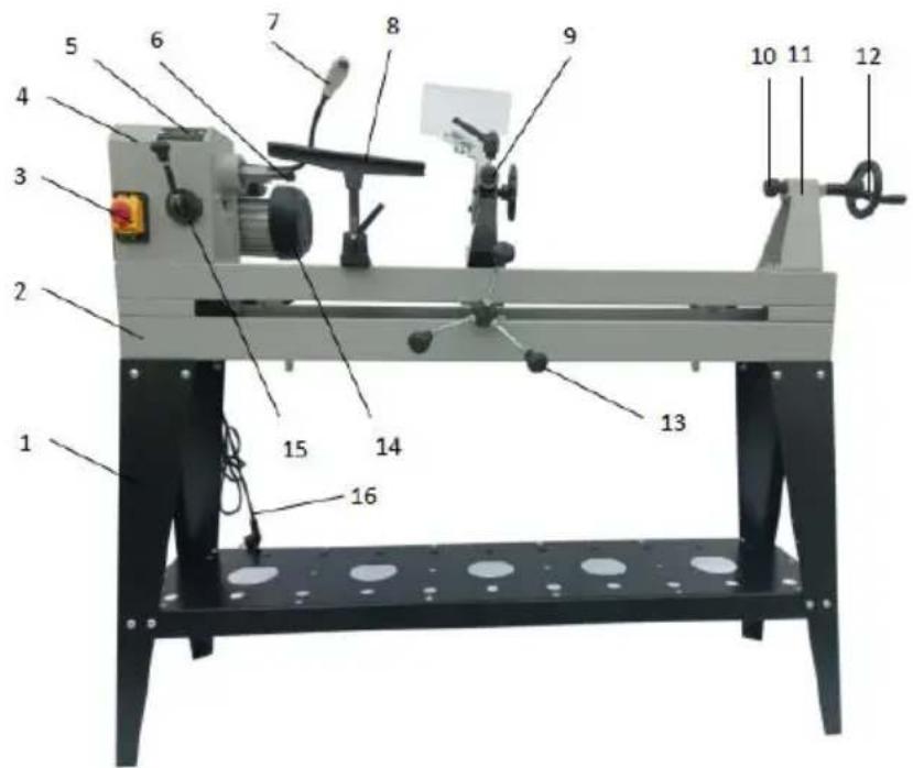
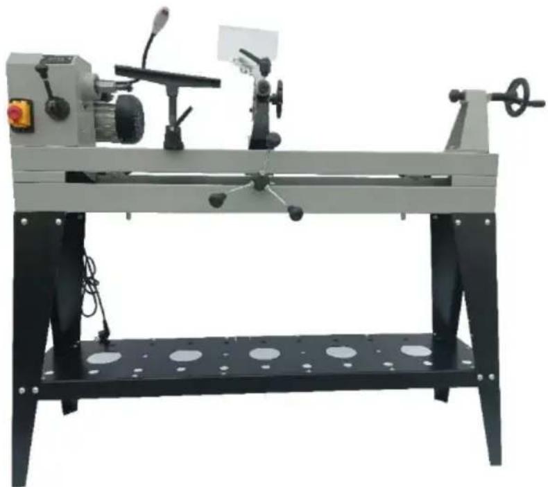
Know Your Wood Lathe: (Fig. 1)
| PART NO. | DESCRIPTION | QTY |
| 1 | Stand | 1 |
| 2 | Machine Bed | 1 |
| 3 | Switch | 1 |
| 4 | Head stock | 1 |
| 5 | Digital Indicator | 1 |
| 6 | Spur center | 1 |
| 7 | Light | 1 |
| 8 | Tool rest | 1 |
| 9 | Copying Device | 1 |
| 10 | Living center | 1 |
| 11 | Tail stock | 1 |
| 12 | Hand wheel | 1 |
| 13 | Digital Indicator | 1 |
| 14 | Speed controller | 1 |
| 15 | Power cord | 1 |
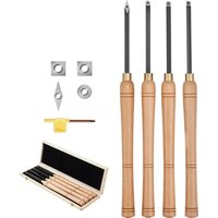
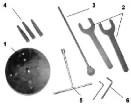
Standard accessories
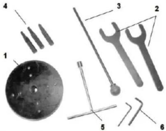
| PART NO. | DESCRIPTION | QTY |
| 1 | Face Plate | 1 |
| 2 | Wrench | 2 |
| 3 | Rod injection | 1 |
| 4 | Lathe tool rest | 3 |
| 5 | T-wrench | 1 |
| 6 | Allen Wrench SW 3, SW 4 | 2 |
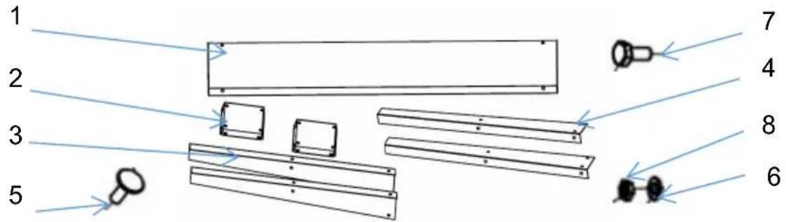
Stand accessories
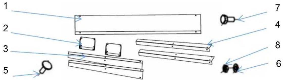
| PART NO. | DESCRIPTION | QTY |
| 1 | Tool rack | 1 |
| 2 | Stand upper cover | 2 |
| 3 | Front stand (right) | 2 |
| 4 | Front stand (left) | 2 |
| 5 | Cup head square neck bolt M8x12 | 24 |
| 6 | Washe 8 | 32 |
| 7 | Bolt M8X16 | 8 |
| 8 | Nut M8 | 32 |
The machine must only be used for its intended purpose! Any other use deemed to be a case of misuse.
To use the machine properly you must also observe and follow all safety regulations, the assembly instructions, operating and maintenance instructions lay down in this manual.
All people who use and service the machine have to be acquainted with this manual and must be informed about the machine's potential hazards. It is also imperative to observe the accident prevention regulations in force in your area.
The same applies for the general rules of occupational health and safety. The machine is used for:
Turning wood.
Any manipulation of the machine or its parts is a misuse, in this its sales partners cannot be made liable for ANY direct or indirect damage.
Even when the machine is used as prescribed it is still impossible to eliminate certain residual risk factors.
| WARNING | |
| Use the machine never with defective or without mounted gThe removal or modification of the safety components may result in damage to equipment and serious injury!HIGHEST RISK OF INJURY! |
Ambient conditions
The machine may be operated:
| Humidity | Max. 70% |
| Temperature | +5°C to +40°C (+41°F to +104°F) |
The machine shall not be operated outdoors or in wet or damp areas. The machine shall not be operated in areas exposed to increased fire or explosion hazard.
Prohibited use
The operation of the machine outside the stated technical limits described in this manual is forbidden.
Operation of the machine function without emergency stop button or impeller box with open doors is prohibited.
The use of the machine not according with the required dimensions is forbidden.
The use of the machine not being suitable for the use of the machine and not being certified is forbidden.
Any manipulation of the machine and parts is forbidden.
The use of the machine for any purposes other than described in this user-manual is forbidden.
The unattended operation on the machine during the working process is forbidden!
It is not allowed to leave the immediate work area during the work is being performed.
UNPACKING AND CLEANING
- Remove the woodworking lathe from the box
- Check all the accessories of the machine tool according to the packing list.
- Choose a location for the lathe that is dray, has good lighting and has enough room to be able to service the lathe on all four sides.
- To avoid twisting the bed, the lathe's location must be absolutely flat level. Bolt the lathe to the stand (if used).
- Clean all rust protected surfaces using a mild commercial solvent, kerosene or diesel fuel. Do not use paint thinner, gasoline or lacquer thinner. These will damage painted surfaces. Cover all cleaned surfaces with a light film of 20W machine oil.
Preparatory activities
Delivery content
Please check the product contents immediately after receipt for any eventual transport damage or missing parts. Claims from transport damage or missing parts must be placed immediately after initial machine receipt and unpacking before putting the machine into operation. Please understand that later claims cannot be accepted anymore.
Workplace requirements
The workplace has to fulfill the requirements.
The ground has to be even, in level and hard. It must be suitable at least weight it with double weight per square meter than the machines net weight.
The chosen workplace must have access to a suitable electric supply net hat complies with the machines requirements.
Transport
The machine can be transported in package with a forklift.
The machine is very heavy. The machine shall be lifted from crate with suitable lifting device only that is certified to be able to carry the machine load.

WARNING
The lifting and transportation of the machine must only be car out by qualified staff and must be carried out with appropriate equipment.
Note that lifting equipment used (crane, forklift, sling, etc.) must be in perfect condition.
To maneuver the machine in the packaging can also a pallet jack or a forklift be used.
Preparation of the surface
Uncoated metal machine parts have been insulated with a greasy layer to inhibit corrosion.
This layer has to be removed. You can use standard solvents that do no damage the machine surface.
 | NOTICE |
| ● Do not use solvents based on nitrite, aggressive solvents libreak cleaners or scrubbing agents!● These damage the machine surface. |
Power supply
 | ATTENTION |
| When working with non-grounded machines:Severe injury or even death may arise though electrocution!Therefore: The machine must be operated at a grounded po socket |
The connection of the machine to the electric power supply and the following checks have to be carried out by a respectively trained electricia only.
a. The electronic connection of the machine is designated for operation with a grounded power socket!
b. The mains supply must be secured with 16A:
c. If the connector plug doesn't fit or if it is defect, only qualified electricians may modify or re-new it!
d. The grounding wire should be held in green-yellow.
e. A damaged cable has to be exchanged immediately!
f. Check, whether the feeding voltage and the Hz comply to the required values of the machine. A deviation of feeding voltage of ±5% is allowed.
g. After connecting, check the right running direction!
h. Make sure that a possible extension cord is in good condition and suitable for the transmission of power. An undersized cord reduces the transmission of power and heats up.
Assembly
| Prepare parts and install the stand as shown in right pictures.Assemble the stand according to the figure. Take care that screws are not tightened at the same time. Thus it is easier to position mounting ho and fix the screws. | 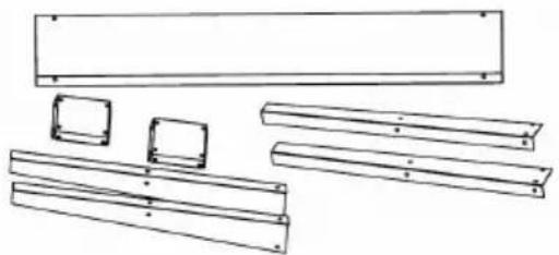 |
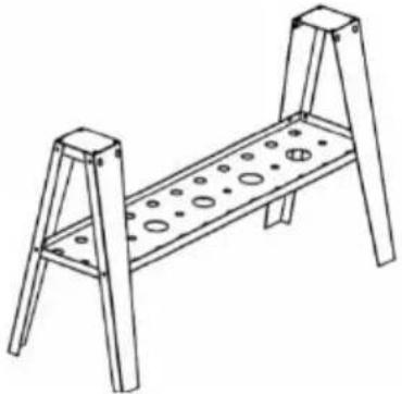 | |
| Position the head stock over the top plate and align the holes in the bed with the holes in tope plate.Set the lathe on the stand by tightening the boltAssemble the stand according to the figure. Take care that screws are not tightened at the same time. Thus it is easier to position mounting ho and fix the screws. | 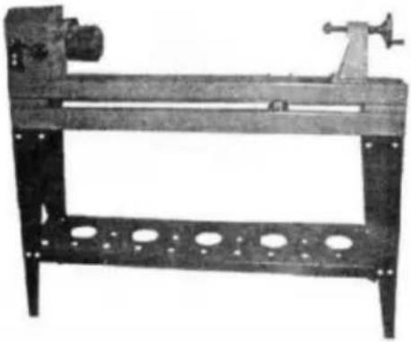 |
| ● On principle short-fibred harder wood stored in dry place is more suitable than long-fibred sof fresh wood.● Wood from fruit and leafy trees and walnut tre are very suitable.Prepare the wood preferably saw cutting for the thickness later required (possibly also by splitting). It should be stored without sun radiation in a dry and● Properly ventilated room.● Approximate rule for wood drying: for the thickness of 1 cm = 1 year.● Thus one can avoid wood cracking by far. | PREPARATION |
| ● Unmachined pieces or wood to be turned mus be balance centred between carrying side (machine side) and the side of collateral run (tailstock) to avoid accidents as a result of possible tearing the workpiece off during machining! Pay attention using roundwood or timber coming in parallel direction if possible.● Determine the centre of your unmachined piec by drawing whilst determining the centre using pin or marking awl and using the ruler or cen angle (available as optional accessory)● Abb. 4 A + B: Centre location over the unmachined piece edges● Abb. 4 C: Centre location using the centring angle (available as an optional accessory)● Abb. 4 D: Centre fixation using a hammer and centre punch | 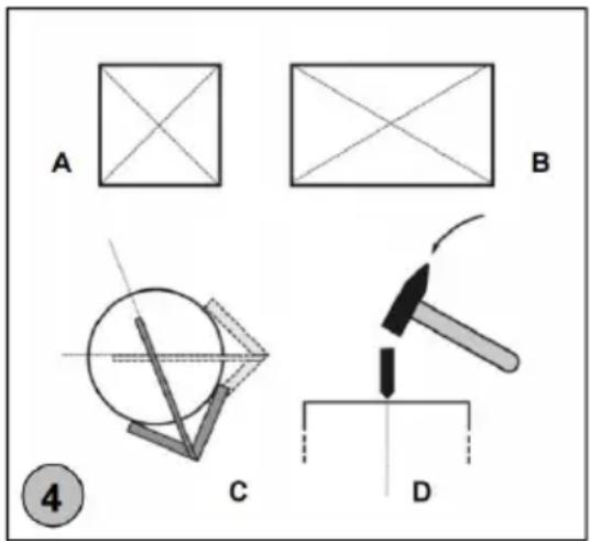 |
| ● Roughing: Thick and strong removal of workpiece material to form a rough contour (revolutions 800-1500 rev/min.).● Smoothing: Tiny, fine chip removal to produce fine contours (revolutions 1500-2000 rev /min.) | Basic terms |
| ● Grinding: Final working up the workpiece using abrasive rope or paper (revolutions 0-2000 ot./min.).● Polishing: working up the workpiece using a or fleece with allowance of polishing agents – pastes, oils, agents for wood treatment or greases (available as optional accessory. | |
| ● Assembled lathe with stand● Finally assembled lathe with clamped copying template | 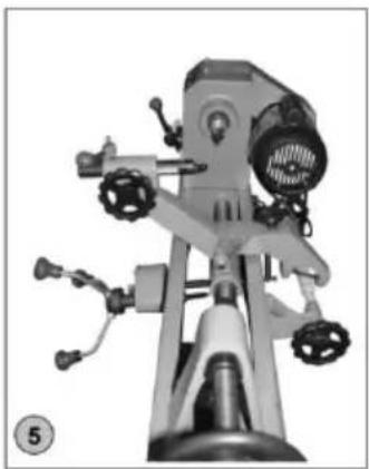 |
| ● COPYING ARM INSTALLATION● Insert the copying arm between both holding straps located at the slide and shift the joint pi (item 73) to the bearing opening. Tighten nuts both sides (Fig. 6)● ATTENTION: Do not tighten too firmly, the arm should stay movable. | 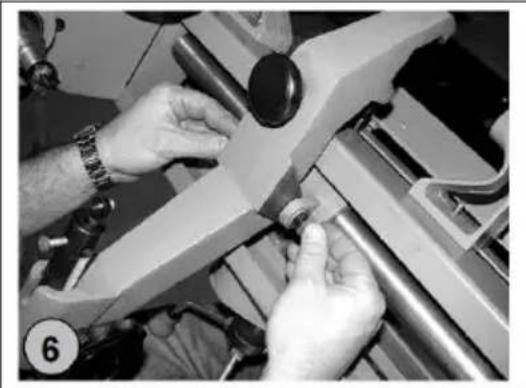 |
| ● SLIDING WHEEL INSTALLATION● Shifthe sliding wheel to the sled axis.● Securing is done using the Allen screw at the circumference of the sliding wheel (Fig. 7) | 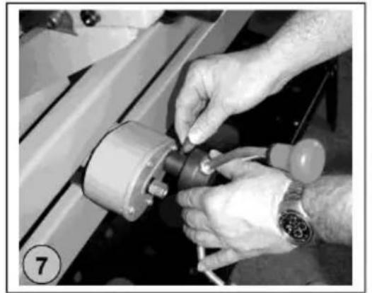 |
| Mount the supporting tool holder and base pla to the machine bed and tighten. (Fig. 8) | 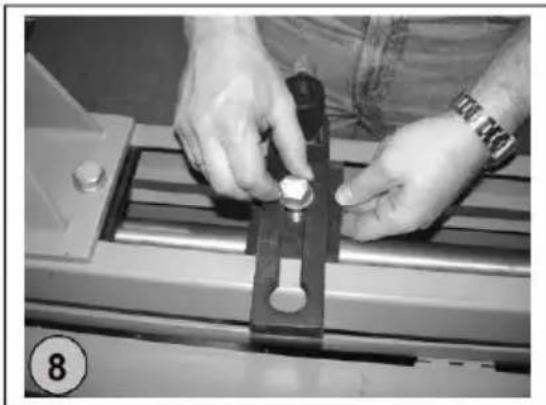 |
| Then the tool support is fixed by clamping bo the supporting carrier of the tool (Fig. 9). Plac the tool support as close to the workpiece as possible.The workpiece must not be in contact with the tool support during turning. Turn the workpiece by hand before you start the work to ensure runs freely. | 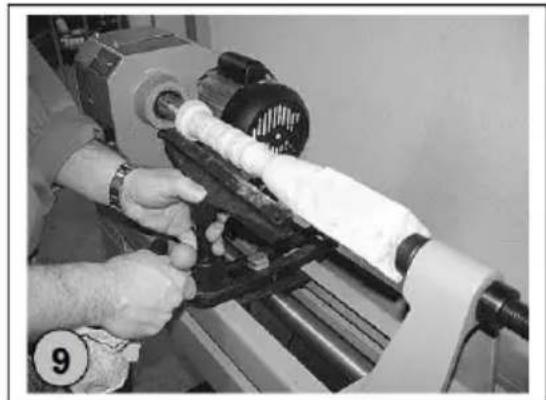 |
| REVOLUTION ADJUSTMENTThanks to the special gearbox with variable be pulleys the machine revolution can be adjusted continuously allowing exact analogue adjustmer of revolutions being indicated in digital form at gearbox.(Fig. 10) | 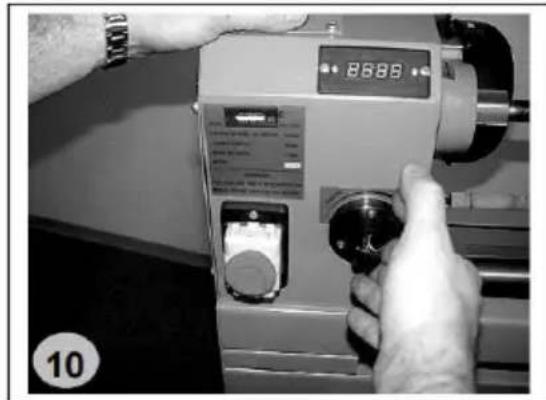 |
| Always lower the machine revolutions to the minimum value before its stopping; its starting again will be made much easier thus. | Attention! |
| Roughing and smoothing: lay the turning chisel - see the figure - down on the tool support ho it with both hands firmly and safely and take that chip removal takes place at the central a height and sufficient stressing angle is availab (see schematic drawing). Use only exactly sharpened and sharp turning tools. (Fig. 11). | 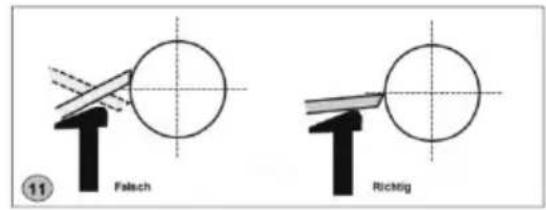 |
| To remove the carrying point direct the ejectin broach from the left side of the machine through spindle hole (Fig. 12) and strike the carrying strongly from the cone (this also holds for all clampable tools with conical grip MK2) | 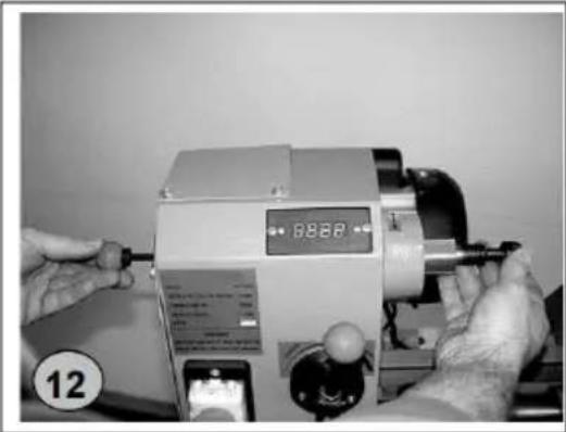 |
| To turn plates or bowls remove the carrying p (Fig. 13) and turn the face plate to the spindle thread. | 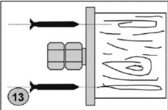 |
| For copying the copying arm must be installed between tailstock and carrying point. To place copying device between tailstock and carrying point or face plate the gripping screws on the tailstock must be dismounted (Fig. 14) and the tailstock must be removed. | 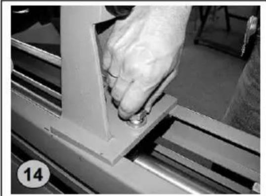 |
| Now the gripping plate should be split by loosening both screws (Fig. 15) | 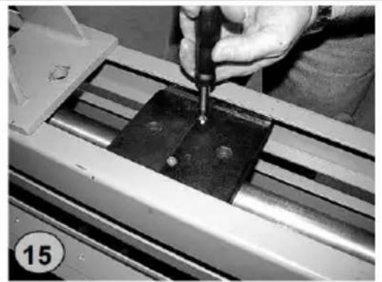 |
| Having this done the plates are to be remove (Fig. 16), again replaced behind the copying a and tailstock reinstalled. | 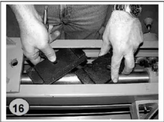 |
| Copied original will be clamped between centri points of copying grips. Now moving in (holding-down pressure of the copying arm) ca be adjusted using stressing screw (Fig. 17) | 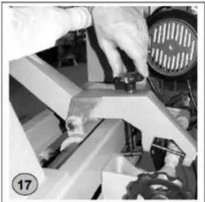 |
| Copying tool should be set to the largest diameter.The workpiece is then moved along the whole length of the copying pattern uniformly until archip removal occurs.Copying tools are adjusted by turning the han wheel and secured by clamping screw until required contour or required diameter is attaine (Fig. 18). |  |
| Copying templates can be made of various materials, veneered plywood is perfectly suitable The template is similar to the contour of the to be turned. (Fig. 19) | 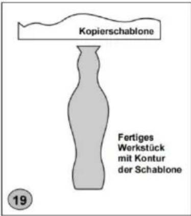 |
| To use the copying template as a pattern lift holding device up and secure between centring points of copying grips (Fig. 20). | 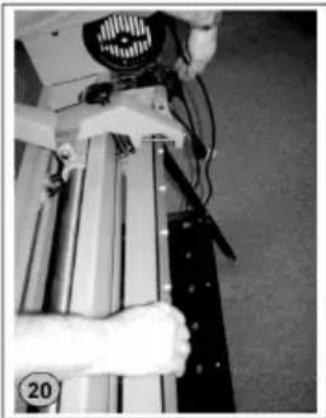 |
| Loosen clamping screws of the holding lath (F 21) to allow stretching the template.During turning the template is moved along as often as required contour is formed at the workpiece | 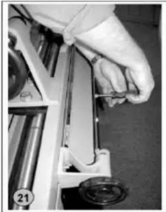 |

WARNING
● The leg set must be fastened to the supporting surface!
- Do not operate your wood lathe until it is completely assemble an adjusted according to the instruction!
OPERATION
Device to be operated in a perfect state only. Inspect the device visually every time it is to be
used. Check in particular the safety equipment, electrical controls, electric cables and screwed
connection for damage and if tightened properly. Replace any damaged parts before operating
the device.
 | WARNING |  |
| Perform all machine settings with the machine being disconnected from the power supply! |
Operation instructions
 | ATTENTION |
| Never switch the machine on while pressing the chisel against material! |
 | NOTICE |
| Before switching the machine on, make sure that the tool rest firmly tightenedRotate the clamped workpiece each time before turning by hand ensure that it runs freely and does not touch the rest tool!Thereby check also whether the workpiece is centred and tighten clamped!Make sure to guide and hold the chisel with both hands safe a tight during machining!Work only with well sharpened tools!Work large and unbalanced workpieces at low spindle speed onSpecifications regarding the maximum or minimum size of the workpiece must be observed!Workpieces with cracks may not be used!Only process selected woods without defects! |
Operation
On-Off-switch
Switch on: Push the green button ("I") for 2 seconds. The machine begins to run.
Switch off: Push the red button ("0").
The machine does not stop immediately! Stay as long at the machine, up the workpiece is completely stopped (Do not stop the workpiece by hand
Speed adjustment
The speed can be set infinitely variable by turning the speed control level
 | NOTICE | 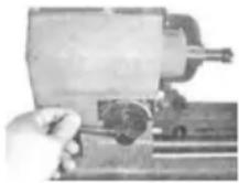 |
| You must move the lever to the lowest speed sett before turning the switchON/OFF, otherwise the motor may not start! |
Tool rest
 | NOTICE |
| The tool rest should be selected as close as possible to the workpiece!Height adjustment just below the centerline of the workpiece.Rotate the workpiece by hand and check that the workpiece can rotate freely before turning! |
MAINTENANCE
 | ATTENTION |  |
| Perform all maintenance machine settings with the machine being disconnected from the power supply!Serious injury due to unintentional or automatic activ of the machine! |
The machine does not require extensive maintenance. If malfunctions and defects occur, let it be serviced by trained persons only.
Before first operation as well as later on every 100 operation hours you should lubricate all connecting parts (if required, remove beforehand with brush all swarfs and dust).
Check regularly the condition of the security stickers. Replace them if required.
Check regularly the condition of the machine.
The good condition and perfect adjustment of the guiding rollers is essential for a smooth band guidance and a clean cut.
Store the machine in a closed, dry location.
NOTICE
Clean your machine regularly after every usage – it prolongs the machine lifespan and is a pre-requisite for a safe working environment.
Repair jobs shall be performed by respectively trained professional
Maintenance plan
After each workshift:
Clean the machine and its parts with a strong jet of compressed air from wood dust and other material remains. Moving parts can also be cleaned with a brush or a soft brush. Apply a thin layer of lubricating oil to all n parts of the machine.
After 50 hours of operation
Check the V-belts.
Determine for frayed belts cause. Check if uneven or rough surfaces and were built on the V-belt
pulleys. Replace frayed or stretched belts!
Cleaning
After each workshift the machine has to be cleaned. Remove chips etc. with a suitable tool. Do not remove them by hand (cutting injury!). Remo dust as well.
 | NOTICE |
| The usage of certain solutions containing ingredients damaging m surfaces as well as the use of scrubbing agents will damage the machine surface!Clean the machine surface with a wet cloth soaked in a mild so |
Disposal
Do not dispose the machine in residual waste. Contact your local authorities for information regarding the available disposal options. When you buy at your local deal for a replacement unit, the latter is obliged to exchange your old.
TROUBLE SHOOTING
BEFORE YOU START WORKING FOR THE ELIMINATION OF DEFECTS, DISCONNECT THE
MACHINE FROM THE POWER SUPPLY.
| Trouble | Possible cause | Solution |
| Machine does not start | Switch defective | Repair switch |
| Power supply is off | Repair power supply | |
| Fuse is defective | Change fuse | |
| Circuit breaker is active | Push in the circuit button | |
| Strong vibration | Warped workpiece | Change material |
| Workpiece is wrong centered | Measure the center newly | |
| Loosen pulley | Tighten the pulley | |
| Outworn pulley | Change pulley | |
| Turning lathe is on uneven surface | Level the surface | |
| Loosen tail- or headstock | Tighten | |
| Too much speed | Adjust speed | |
| Bad turning result | bad sharpened chisel | Sharpen the chisel |
| Wrong chisel for this work | Select the right chisel | |
| Wrong adjustment of tool rest | Adjust the high and the distance of the tool rest |
MANY POTENTIAL SOURCES OF ERROR CAN BE CLEARED BY THE EXPERTLY
CONNECTION TO THE ELECTRICITY GRID.

NOTICE
Should you in necessary repairs not able to properly to perform you have not the prescribed training for it always attract a problem to fix the problem.
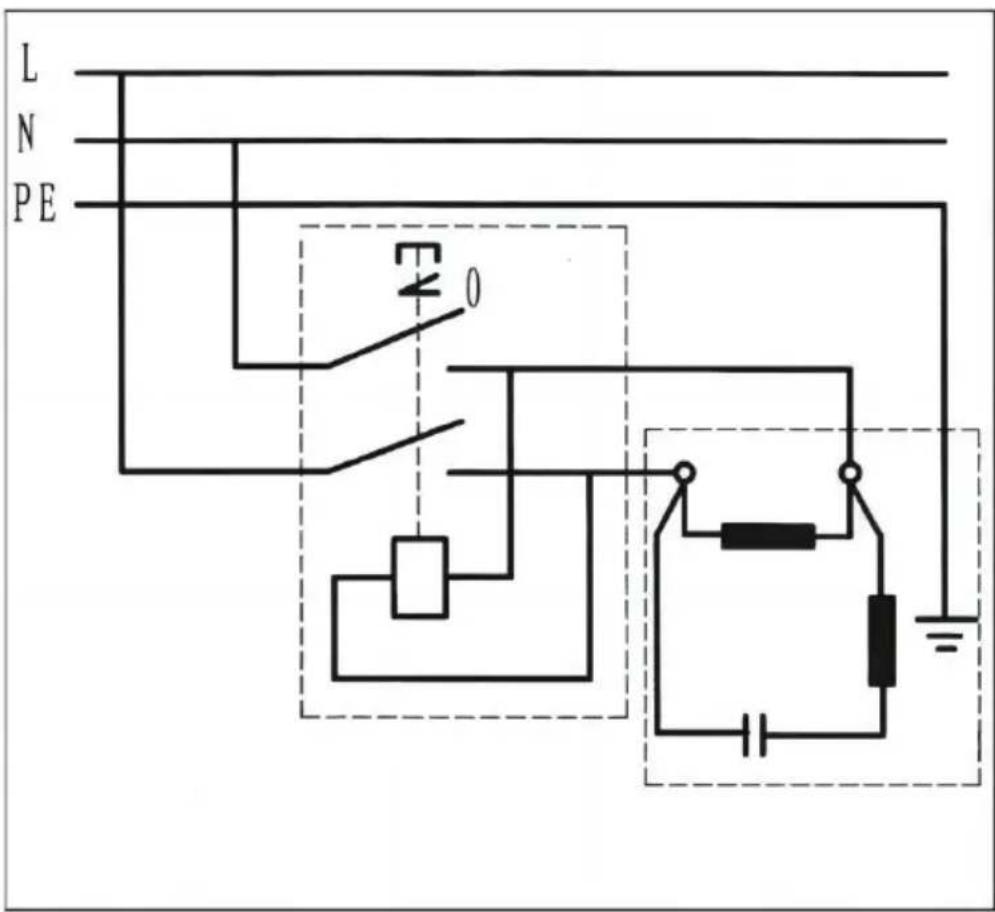
SCHALTPLAN / WIRING DIAGRAM
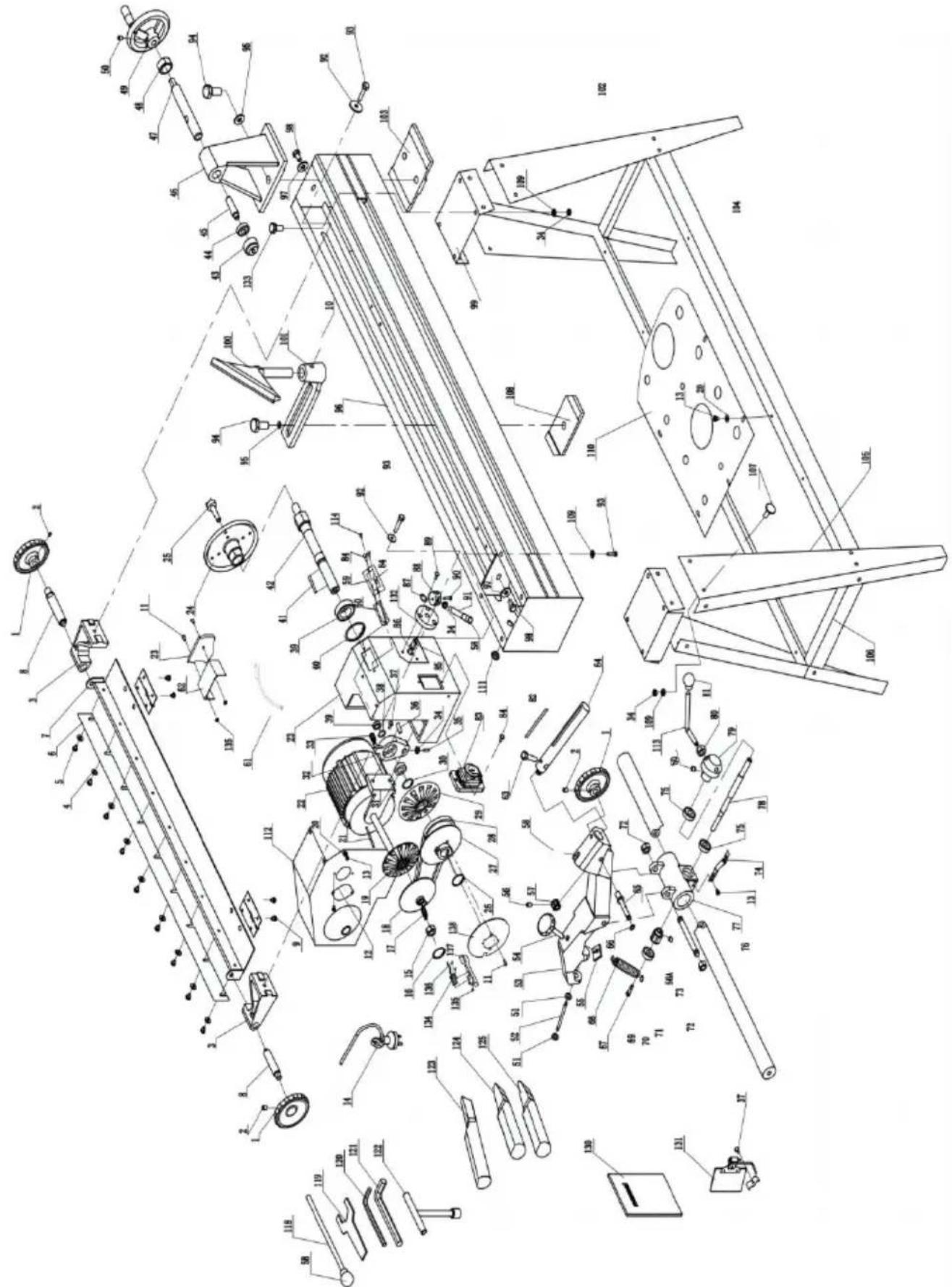
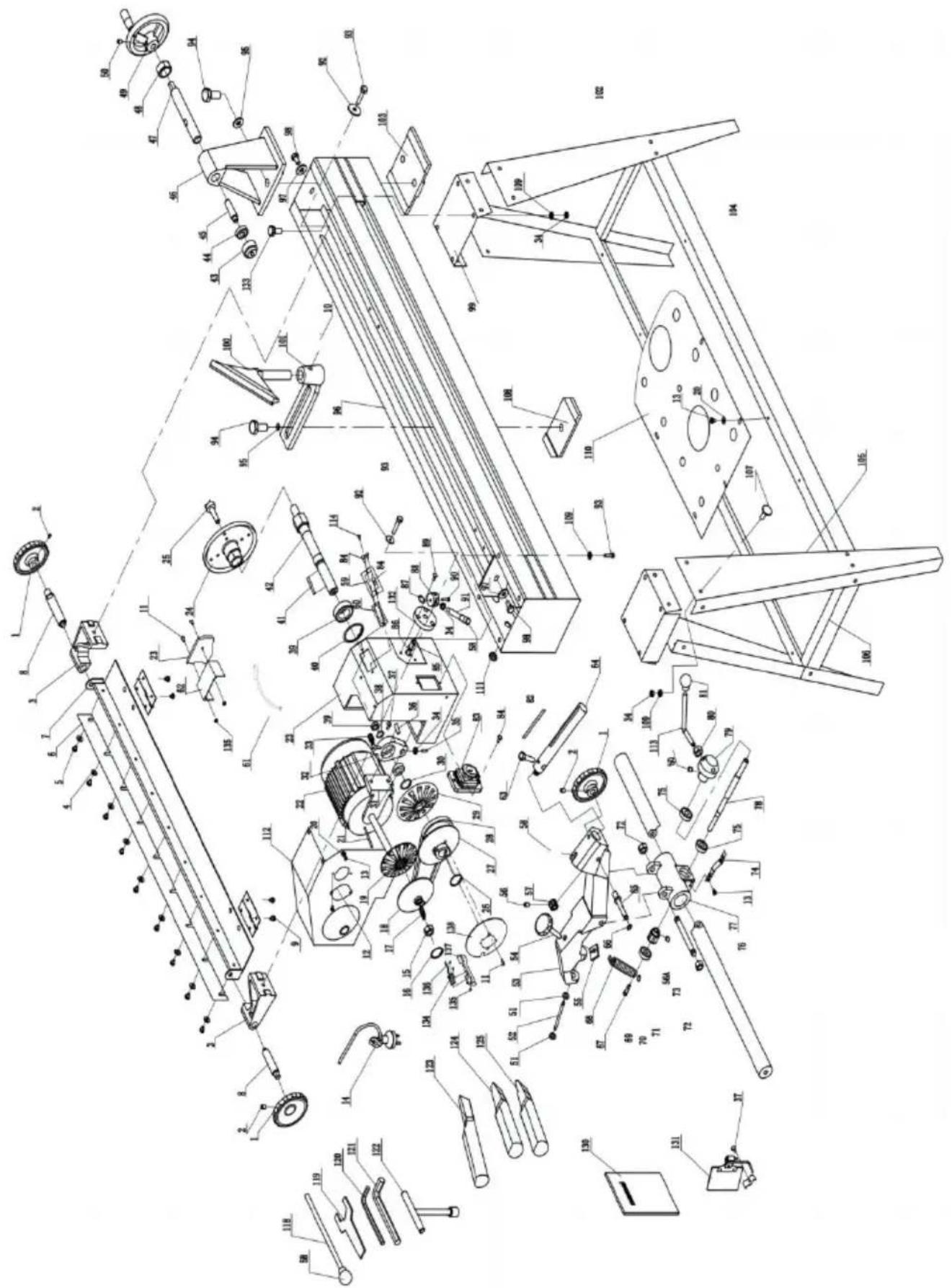
| Part List for Wood Lathe | ||||||||
| Item | Description | Q'ty | Item | Description | Q'ty | Item | Description | Q'ty |
| 1 | Hand wheel | 3 | 45 | Taper shank | 1 | 88 | Eccentric shaft | 1 |
| 2 | Screw M6X10 | 5 | 46 | Tail stock | 1 | 89 | Flat head screw M5X20 | 4 |
| 3 | Stand | 2 | 47 | Tail stock spindle M24 | 1 | 90 | Pin | 1 |
| 4 | Washer Φ6 | 9 | 48 | Nut | 1 | 91 | Rod | 1 |
| 5 | Screw M6X8 | 9 | 49 | Hand wheel | 1 | 92 | Washer Φ8 | 2 |
| 6 | Mould plate | 1 | 50 | Screw M8X8 | 2 | 93 | Bolt M8X25 | 2 |
| 7 | Mobile plate | 1 | 51 | Bearing 625-2Z | 2 | 94 | Bolt M16X35 | 3 |
| 8 | Leading screw M18 | 2 | 52 | Living roller pin | 1 | 95 | Washer Φ16 | 3 |
| 9 | Bolt M6X8 | 4 | 53 | Cutter mount | 1 | 96 | Bed | 1 |
| 10 | Lock the handle | 1 | 54 | Cutter feeder adjustment screw | 1 | 97 | Washer Φ10 | 2 |
| 11 | Screw M4X8 | 3 | 55 | Sleeve | 1 | 98 | Bolt M10X18 | 2 |
| 12 | Cap spindle end | 1 | 56 | Screw M5X6 | 1 | 99 | Stand upper cover | 2 |
| 13 | Screw M5X8 | 9 | 564 | Screw M6X8 | 1 | 100 | Tool rest | 1 |
| 14 | Power cord | 1 | 57 | Cutter rest gear | 1 | 101 | Tool rest holder | 1 |
| 15 | Sleeve | 1 | 58 | Lock the handle | 1 | 102 | Front stand(right) | 1 |
| 16 | Retaining ring 16 | 1 | 59 | Fixed panel for display screen | 1 | 103 | Fixing block | 1 |
| 17 | Spring | 1 | 60 | Speed display circuit board | 1 | 104 | Long cross support | 1 |
| 18 | Pulley motor(left) | 1 | 61 | Lights | 1 | 105 | Front stand(left) | 1 |
| 19 | Pulley motor(right) | 1 | 62 | Transformers | 1 | 106 | Short cross support | 1 |
| 20 | Washer Φ5 | 5 | 63 | Bolt M6X25 | 1 | 107 | Cup head square neck bolt M8X12 | 24 |
| 21 | Key | 1 | 64 | Rack | 1 | 108 | Fixing block | 1 |
| 22 | Motor | 1 | 65 | Cutter mount spindle | 1 | 109 | Washer Φ8 | 38 |
| 23 | Head stock | 1 | 66 | "C"ring 8 | 1 | 110 | Plate | 1 |
| 24 | Face plate | 1 | 67 | Screw | 1 | 111 | Strain relief M16X1.5 | 1 |
| 25 | Spur center | 1 | 68 | Spring | 1 | 112 | Belt guard | 1 |
| 26 | Retaining ring 24 | 1 | 69 | "C"ring 8 | 1 | 113 | Crank | 3 |
| 27 | Pulley spindle(left) | 1 | 70 | Bearing 80200 | 1 | 114 | Tapping screws ST2.2×6.5 | 2 |
| 28 | Belt Z560 | 1 | 71 | Gear | 1 | 118 | Hit rod | 1 |
| 29 | Pulley spindle(right) | 1 | 72 | Nut M12 | 1 | 119 | Spanner | 1 |
| 30 | Retaining ring 62 | 1 | 73 | Stud bolt | 1 | 120 | Wrench S3 | 1 |
| 31 | Bearing 6007-2Z | 1 | 74 | Brush rest | 2 | 121 | Wrench S4 | 1 |
| 32 | Bracket-shifting lever | 1 | 75 | Bearing 80201 | 2 | 122 | "T"wrench | 1 |
| 33 | Spring | 1 | 76 | sliding guide | 1 | 123 | Sharp tool | 1 |
| 34 | Nut M8 | 34 | 77 | 3-way milling | 1 | 124 | Head tool | 1 |
| 35 | Screw M8X25 | 1 | 78 | Gear-end pinion | 1 | 125 | Arctool | 1 |
| 36 | Shaft-pinion | 1 | 79 | Hub | 1 | 130 | Handbook | 1 |
| 37 | Hex HD screw M8X2 | 2 | 80 | Nut M10 | 3 | 131 | Goggle | 1 set |
| 38 | Retaining ring 25 | 1 | 81 | Knob | 3 | 132 | Fixing plate | 1 |
| 39 | Bearing 6205-2Z | 1 | 82 | Scale | 1 | 133 | Bolt M8X16 | 8 |
| 40 | Retaining ring 52 | 1 | 83 | Switch | 1 | 134 | Speed sensor | 1 |
| 41 | Spindle key | 1 | 84 | Screw M4X12 | 2 | 135 | Nut M4 | 2 |
| 42 | Spindle | 1 | 85 | Shaft-pinion | 1 | 136 | Screw M3X10 | 2 |
| 43 | Living center | 1 | 86 | Speed label | 1 | 137 | Probe support plate | 1 |
| 44 | Bearing 80201 | 1 | 87 | "C" ring 3 | 1 | 138 | Sensing Plate | 1 |
VEVOR®
TOUGH TOOLS, HALF PRICE
Technical Support and E-Warranty Certificate
www.vevor.com/support
VEVOR®
TOUGH TOOLS, HALF PRICE
MANUEL D'INSTRUCTIONS
MODÈLE: WL-1000GV
We continue to be committed to provide you tools with competitive price. "Save Half", "Half Price" or any other similar expressions used by us only represer estimate of savings you might benefit from buying certain tools with us compared to top brands and does not necessarily mean to cover all categories of tools offered by are kindly reminded to verify carefully when you are placing an order with us if yo actually saving half in comparison with the top major brands.
VEVOR®
TOUGH TOOLS, HALF PRICE
WOOD LATHE
MODÈLE : WL-1000GV

natural_image
Industrial machine with adjustable arms and a black base plate (no visible text or symbols)NEED HELP? CONTACT US!
Have product questions? Need technical support? Please feel free contact us:
Technical Support and E-Warranty Certificate www.vevor.com/support
This is the original instruction, please read all manual instructions carefully before operating. VEVOR reserves a clear interpretation of user manual. The appearance of the product shall be subject to the product you received. Please forgive us that we won't inform you there are any technology or software updates on our product.
Accessoires standards
UNPACKING AND CLEANING
AVERTISSEMENT
natural_image
Technical line drawing of mechanical components including rectangular and cylindrical parts (no text or symbols)EXPLOSIONSZEICHNUNG / EXPLOSION DRAWING
We continue to be committed to provide you tools with competitive price. "Save Half", "Half Price" or any other similar expressions used by us only represer estimate of savings you might benefit from buying certain tools with us compared to top brands and does not necessarily mean to cover all categories of tools offered by are kindly reminded to verify carefully when you are placing an order with us if yo actually saving half in comparison with the top major brands.
VEVOR®
TOUGH TOOLS, HALF PRICE
WOOD LATHE
MODELL: WL-1000GV

natural_image
Industrial machine with adjustable arms and a black base plate (no visible text or symbols)NEED HELP? CONTACT US!
Have product questions? Need technical support? Please feel free contact us:
Technical Support and E-Warranty Certificate www.vevor.com/support
This is the original instruction, please read all manual instructions carefully before operating. VEVOR reserves a clear interpretation of user manual. The appearance of the product shall be subject to the product you received. Please forgive us that we won't inform you there are any technology or software updates on our product.
WARNUNG
EXPLOSIONSZEICHNUNG / EXPLOSION DRAWING

www.vevor.com/support
VEVOR®
TOUGH TOOLS, HALF PRICE
We continue to be committed to provide you tools with competitive price. "Save Half", "Half Price" or any other similar expressions used by us only repressor estimate of savings you might benefit from buying certain tools with us compared to top brands and does not necessarily mean to cover all categories of tools offered by are kindly reminded to verify carefully when you are placing an order with us if yo actually saving half in comparison with the top major brands.
VEVOR®
TOUGH TOOLS, HALF PRICE
WOOD LATHE
MODELLO: WL-1000GV
natural_image
Industrial machine with adjustable arms and a black base plate (no visible text or symbols)NEED HELP? CONTACT US!
Have product questions? Need technical support? Please feel free contact us:
Technical Support and E-Warranty Certificate www.vevor.com/support
This is the original instruction, please read all manual instructions carefully before operating. VEVOR reserves a clear interpretation of user manual. The appearance of the product shall be subject to the product you received. Please forgive us that we won't inform you there are any technology or software updates on our product.
AVVERTIMENTO
UNPACKING AND CLEANING
natural_image
Technical line drawing of mechanical components including plates and brackets (no text or symbols)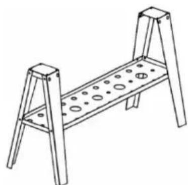
natural_image
Line drawing of a simple metal frame structure with two supports and a perforated base (no text or symbols)natural_image
Close-up of a person using a mechanical tool on a vehicle (no visible text or symbols)
AVVERTIMENTO
ATTENZIONE
www.vevor.com/support
VEVOR®
TOUGH TOOLS, HALF PRICE
We continue to be committed to provide you tools with competitive price. "Save Half", "Half Price" or any other similar expressions used by us only repressor estimate of savings you might benefit from buying certain tools with us compared to top brands and does not necessarily mean to cover all categories of tools offered by are kindly reminded to verify carefully when you are placing an order with us if you actually saving half in comparison with the top major brands.
VEVOR®
TOUGH TOOLS, HALF PRICE
WOOD LATHE
MODELO: WL-1000GV

natural_image
Industrial machine with adjustable arms and a black base plate (no visible text or symbols)NEED HELP? CONTACT US!
Have product questions? Need technical support? Please feel free contact us:
Technical Support and E-Warranty Certificate www.vevor.com/support
This is the original instruction, please read all manual instructions carefully before operating. VEVOR reserves a clear interpretation of user manual. The appearance of the product shall be subject to the product you received. Please forgive us that we won't inform you there are any technology or software updates on our product.
ADVERTENCIA
ADVERTENCIA
UNPACKING AND CLEANING
ADVERTENCIA
EXPLOSIONSZEICHNUNG / EXPLOSION DRAWING

www.vevor.com/support
VEVOR®
TOUGH TOOLS, HALF PRICE
We continue to be committed to provide you tools with competitive price. "Save Half", "Half Price" or any other similar expressions used by us only repressor estimate of savings you might benefit from buying certain tools with us compared to top brands and does not necessarily mean to cover all categories of tools offered by are kindly reminded to verify carefully when you are placing an order with us if you actually saving half in comparison with the top major brands.
VEVOR®
TOUGH TOOLS, HALF PRICE
WOOD LATHE
MODEL: WL-1000GV

natural_image
Industrial machine with adjustable arms and a black base plate (no visible text or symbols)NEED HELP? CONTACT US!
Have product questions? Need technical support? Please feel free contact us:
Technical Support and E-Warranty Certificate www.vevor.com/support
This is the original instruction, please read all manual instructions carefully before operating. VEVOR reserves a clear interpretation of user manual. The appearance of the product shall be subject to the product you received. Please forgive us that we won't inform you there are any technology or software updates on our product.
OSTRZEŻENIE
UNPACKING AND CLEANING
OSTRZEŻENIE
natural_image
Technical line drawing of mechanical components including rectangular and rectangular parts (no text or symbols)EXPLOSIONSZEICHNUNG / EXPLOSION DRAWING

www.vevor.com/support
VEVOR®
TOUGH TOOLS, HALF PRICE
Technisch Ondersteuning en E-garantiecertificaat www.vevor.com/support
HOUTDRAAIBANK
GEBRUIKSAANWIJZING
MODEL: WL-1000GV
We continue to be committed to provide you tools with competitive price. "Save Half", "Half Price" or any other similar expressions used by us only repressor estimate of savings you might benefit from buying certain tools with us compared to top brands and does not necessarily mean to cover all categories of tools offered by are kindly reminded to verify carefully when you are placing an order with us if yo actually saving half in comparison with the top major brands.
VEVOR®
TOUGH TOOLS, HALF PRICE
WOOD LATHE
MODEL: WL-1000GV

natural_image
Industrial machine with adjustable arms and a black base plate (no visible text or symbols)NEED HELP? CONTACT US!
Have product questions? Need technical support? Please feel free contact us:
Technical Support and E-Warranty Certificate www.vevor.com/support
This is the original instruction, please read all manual instructions carefully before operating. VEVOR reserves a clear interpretation of user manual. The appearance of the product shall be subject to the product you received. Please forgive us that we won't inform you there are any technology or software updates on our product.
Stellage accessoires
| ONDERDEELNR. | BESCHRIJVING | Hoeveelheid |
| 1 | Gereedschapsrek | 1 |
| 2 | Staand deksel | 2 |
| 3 | Voorstandaard (rechts) | 2 |
| 4 | Voorstandaard (links) | 2 |
| 5 | Kop vierkante kop bout M8x12 | 24 |
| 6 | Wassen 8 | 32 |
| 7 | Bout M8X16 | 8 |
| 8 | Moer M8 | 32 |
UNPACKING AND CLEANING
natural_image
Technical line drawing of mechanical components including plates and brackets (no text or symbols)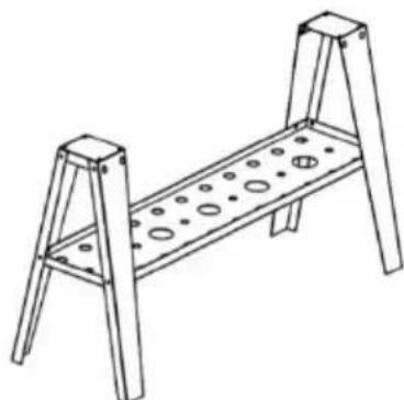
natural_image
Line drawing of a simple metal frame structure with two supports and a perforated base (no text or symbols)natural_image
Close-up of a person using a mechanical tool on a vehicle (no visible text or symbols)
WAARSCHUWING
AANDACHT
EXPLOSIONSZEICHNUNG / EXPLOSION DRAWING

www.vevor.com/support
VEVOR®
TOUGH TOOLS, HALF PRICE
We continue to be committed to provide you tools with competitive price. "Save Half", "Half Price" or any other similar expressions used by us only repressor estimate of savings you might benefit from buying certain tools with us compared to top brands and does not necessarily mean to cover all categories of tools offered by are kindly reminded to verify carefully when you are placing an order with us if yo actually saving half in comparison with the top major brands.
VEVOR®
TOUGH TOOLS, HALF PRICE
WOOD LATHE
MODELL: WL-1000GV

natural_image
Industrial machine with adjustable arms and a black base plate (no visible text or symbols)NEED HELP? CONTACT US!
Have product questions? Need technical support? Please feel free contact us:
Technical Support and E-Warranty Certificate www.vevor.com/support
This is the original instruction, please read all manual instructions carefully before operating. VEVOR reserves a clear interpretation of user manual. The appearance of the product shall be subject to the product you received. Please forgive us that we won't inform you there are any technology or software updates on our product.
WARNING
UNPACKING AND CLEANING
WARNING
EXPLOSIONSZEICHNUNG / EXPLOSION DRAWING

www.vevor.com/support