
DCE050 - Drill DEWALT - Free user manual and instructions
Find the device manual for free DCE050 DEWALT in PDF.

| Product Type | Cordless transfer pump |
| Brand | DeWalt |
| Model | DCE050 |
| Voltage | 18 V DC |
| Battery type | Li-Ion |
| Maximum flow rate | 38 L/min |
| Connections | Male BSPT 3/4" |
| IP rating | IPX4 (splash resistant) |
| Max. water temperature | 60 °C |
| Max. air temperature | 40 °C |
| Max. lift height | 7.5 m (suction), 13.7 m (discharge) |
| Runtime with 5 Ah battery | 1135 L |
| Sound power level | 86 dB(A) |
| Sound pressure level | 74 dB(A) |
| Weight (without battery) | 4 kg |
| Main features | Water transfer, self-priming, dry-run protection, status indicator light |
| Maintenance | Impeller cleaning and O-ring replacement if necessary |
| Safety | Thermal protection, automatic shutdown in case of overload, battery lock |
| Spare parts | O-ring (NA304884) and impeller (NA379414) available |
| Repairability | Repair by qualified personnel only, genuine parts recommended |
Frequently Asked Questions - DCE050 DEWALT
User questions about DCE050 DEWALT
0 question about this device. Answer the ones you know or ask your own.
Ask a new question about this device
Download the instructions for your Drill in PDF format for free! Find your manual DCE050 - DEWALT and take your electronic device back in hand. On this page are published all the documents necessary for the use of your device. DCE050 by DEWALT.
USER MANUAL DCE050 DEWALT
English (original instructions) 18
LEDNINGSFRI OVERF∅RINGSPUMPE
DCE050

Vice President of Engineering Europe
WARNING: Read all safety warnings, instructions, illustrations, and specifications in this manual, including the battery and charger sections provided in an original tool manual or the separate Batteries and Chargers manual. Manuals can be obtained by contacting
Customer Service (refer to the back page of this manual).
Technical Data
| DCE050 | ||
| Voltage V | DC | 18 |
| Type 1 | ||
| Battery type Li-Ion | ||
| Maximum flow rate L/min 38 | ||
| Fittings BSPT male | 3/4" | |
| IP classification | IPX4 | |
Application
| Maximum water temperature 60°C | ||
| Maximum air temperature 40°C | ||
| Maximum water lift height m 7.5 | ||
| Runtime with 5Ah battery pack L 1135 | ||
| Head height 17 L/min at 13.7m | ||
| Noise values (triax vector sum) according to 2006/42/EC, EN ISO 20361: | ||
| Sound power level | L_wAm | 86 dB |
| K (uncertainty for the given sound level) | K_mA | 2.5 dB |
| Sound pressure level | L_PA | 74 dB |
| K (uncertainty for the given sound level) | K_pA | 3.0 dB |
| Weight (without battery pack) kg | 4 kg | |
The vibration and/or noise emission level given in this information sheet has been measured in accordance with a standardised test and may be used to compare one tool with another. It may be used for a preliminary assessment of exposure.
WARNING: The declared vibration and/or noise emission level represents the main applications of the tool. However, if the tool is used for different applications, with different accessories or is poorly maintained, the vibration and/or noise emission may differ. This may significantly increase the exposure level over the total working period. An estimation of the level of exposure to vibration and/or noise should also take into account the times when the tool is switched off or when it is running but not actually doing the job. This may significantly reduce the exposure level over the total working period.
Identify additional safety measures to protect the operator from the effects of vibration and/or noise such as: maintain the tool and the accessories, keep the hands warm (relevant for vibration), organisation of work patterns.
EC-Declaration of Conformity Machinery Directive

Cordless Transfer Pump DCE050 Type 1
We, the manufacturer as stated below, declare that these products described under Technical Data are in compliance with: 2006/42/EC, EN 60335-1:2012 + A1:2019 + A2:2019 + A11:2014 + A13:2017 + A14:2019 + A15:2021 + A16:2023, EN IEC 60335-2-41:2021 + A11:2021, 2000/14/EC Annex V, category Annex I: item 56 L_WA (measured sound power level) 86 dB(A) L_WA (guaranteed sound power) 89 dB(A)
These products also comply with Directive 2014/30/EU and 2011/65/EU. For more information, please contact us at the following address or refer to the back of the manual. The undersigned is responsible for compilation of the technical file and makes this declaration on behalf of the manufacturer.

Markus Rompel
Vice President of Engineering Europe Stanley Black & Decker Deutschland GmbH DEWALT, Richard-Klinger-Straße 11, 65510 Idstein, Germany 31.10.2024

WARNING: To reduce the risk of injury, read the instruction manual.
Definitions: Safety Guidelines
The definitions below describe the level of severity for each signal word. Please read the manual and pay attention to these symbols.
▲ANGER: Indicates an imminently hazardous situation which, if not avoided, will result in death or serious injury.
WARNING: Indicates a potentially hazardous situation which, if not avoided, could result in death or serious injury.
CAUTION: Indicates a potentially hazardous situation which, if not avoided, may result in minor or moderate injury.
NOTICE: Indicates a practice not related to personal injury which, if not avoided, may result in property damage.
Denotes risk of electric shock.
A denotes risk of fire.
General Safety Warnings
WARNING: Read all safety warnings and all instructions.
Failure to follow the warnings and instructions may result in electric shock, fire and/or serious injury.
SAVE ALL WARNINGS AND INSTRUCTIONS FOR FUTURE REFERENCE
Work Area Safety
- Keep work area clean and well lit. Cluttered or dark areas invite accidents.
- Do not operate pump in explosive atmospheres, such as in the presence of flammable liquids, gases or dust. Pump creates sparks which may ignite the dust or fumes.
- Keep children and bystanders away while operating a pump. Distractions can cause you to lose control.
- When operating the pump, the pump must be placed on a stable surface. Since the vibration produced by the pump may cause it to "walk," do not operate on a high shelf or other surface. Operate at ground or bench level only.
Electrical Safety
- Avoid body contact with earthed or grounded surfaces such as pipes, radiators, ranges and refrigerators. There is an increased risk of electric shock if your body is earthed or grounded.
- Do not expose pump/external power supply to rain or wet conditions. Water entering a pump/external power supply will increase the risk of electric shock.
Personal Safety
- Stay alert, watch what you are doing and use common sense when operating a pump. Do not use a pump while you are tired or under the influence of drugs, alcohol or medication. A moment of inattention while operating a pump may result in serious personal injury.
• Always wear ear protection when operating the pump. - Safety goggles should be worn when using the pump in order to protect the eyes against any foreign bodies lifted by the flow of water.
- Dress properly. Do not wear loose clothing or jewellery. Keep your hair, clothing and gloves away from moving parts. Loose clothes, jewellery or long hair can be caught in moving parts.
- Do not open the body casing. There are no user serviceable parts inside.
Use and Care
- Do not use the pump if the switch does not turn it on and off. An pump that cannot be controlled with the switch is dangerous and must be repaired.
• Always use the handle when moving the pump. - Store idle pump out of the reach of children and do not allow persons unfamiliar with the pump or these instructions to operate the pump. Pumps are dangerous in the hands of untrained users.
- Maintain pumps. Check for misalignment or bending of pressurized parts, breakage of parts and any other condition that may affect the operation. If damaged, have the pump repaired before use. Many accidents are caused by poorly maintained pumps.
- For your own safety you must only use the accessories and additional units listed in the operating instructions or recommended or specified by the manufacturer. The use of accessories other than those recommended in the operating instructions or catalog may place your personal safety at risk.
Battery Use and Care
- Recharge only with the charger specified by the manufacturer. A charger that is suitable for one type of battery pack may create a risk of fire when used with another battery pack.
- Use pump only with specifically designated battery packs. Use of any other battery packs may create a risk of injury and fire.
- When battery pack is not in use, keep it away from other metal objects like paper clips, coins, keys, nails, screws or other small metal objects that can make a connection from one terminal to another. Shorting the battery terminals together may cause burns or a fire.
- Under abusive conditions, liquid may be ejected from the battery; avoid contact. If contact accidentally occurs, flush with water. If liquid contacts eyes, additionally seek medical help. Liquid ejected from the battery may cause irritation or burns.
Service
- Have your pump serviced by a qualified repair person using only identical replacement parts. This will ensure that the safety of the pump is maintained.
GENERAL SAFETY INSTRUCTIONS FOR BATTERY-POWERED APPLIANCES
WARNING: RISK OF INJECTION OR INJURY. Do not direct discharge stream at yourself or others.
- Prevent unintentional starting. Ensure the switch is in the off-position before connecting to battery pack, picking up or carrying the appliance. Carrying the appliance with your finger on the switch or energizing appliance that have the switch on invites accidents.
- Disconnect the battery pack from the appliance before making any adjustments, changing accessories, or storing appliance. Such preventive safety measures reduce the risk of starting the appliance accidentally.
- Recharge only with the charger specified by the manufacturer. A charger that is suitable for one type of battery pack may create a risk of fire when used with another battery pack.
- Use appliances only with specifically designated battery packs. Use of any other battery packs may create a risk of injury and fire.
- When battery pack is not in use, keep it away from other metal objects, like paper clips, coins, keys, nails, screws or other small metal objects, that can make a connection from one terminal to another. Shorting the battery terminals together may cause burns or a fire.
- Under abusive conditions, liquid may be ejected from the battery; avoid contact. If contact accidentally occurs, flush with water. If liquid contacts eyes, additionally seek medical help. Liquid ejected from the battery may cause irritation or burns.
- Do not use a battery pack or appliance that is damaged or modified. Damaged or modified batteries may exhibit unpredictable behavior resulting in fire, explosion or risk of injury.
- Do not expose a battery pack or appliance to fire or excessive temperature. Exposure to fire or temperature above 130^ C may cause explosion.
- Have servicing performed by a qualified repair person using only identical replacement parts. This will ensure that the safety of the product is maintained.
- Do not modify or attempt to repair the appliance or the battery pack except as indicated in these instructions for use and care.
Service
- Never service damaged battery packs. Service of battery packs should only be performed by the manufacturer or authorized service providers.
Residual Risks
In spite of the application of the relevant safety regulations and the implementation of safety devices, certain residual risks cannot be avoided. These are:
- Impairment of hearing.
- Risk of personal injury due to flying particles.
- Risk of burns due to accessories becoming hot during operation.
- Risk of personal injury due to prolonged use.
Battery Type
These battery packs may be used:
| Battery (kg) Battery (kg) | |
| DCB546 1.08 DCB185 0.35 | |
| DCB547/G 1.46 DCB187 0.54 | |
| DCB548 1.46 DCB188 0.95 | |
| DCB549 2.12 DCB189 0.54 | |
| DCB181 0.35 DCBP034/G 0.32 | |
| DCB182 0.61 DCBP518/G 0.75 | |
| DCB183/B/G 0.40 DCB1880 0.98 | |
| DCB184/B/G 0.62 DCBP318 0.50 |
Refer to the battery/charger manual for more information.
Markings on Pump
The following pictograms are shown on the pump:

Read instruction manual before use.

Wear ear protection.

Wear eye protection.

Crushing of hand.
IPX4
The construction of the pump has been tested to be safe when exposed to rain for a short periods of time. Follow the instructions provided in the manual.
Date Code Position (Fig. B)
The production date code 6 consists of a 4-digit year followed by a 2-digit week and is extended by a 2-digit factory code.
Description (Fig. A)
WARNING: Never modify the power tool or any part of it. Damage or personal injury could result.
1 Main handle
2 Main housing
3 Horizontal feet
4 Vertical feet
5 On/Off button
6 Battery port cover
7 Battery port cover release button
8 Impeller cover
9 Impeller cover screws
10 Hose connection caps
11 Hose inlet connection
12 Hose outlet connection
13 Male quick connect hose adaptor (2x)
Intended Use
The DCE050 transfer pump is designed for applications such as transferring water from water heaters, tanks, etc. This pump is not weatherproof and is not intended to be used outdoors or inside showers, saunas or other potentially wet or overly humid locations. This pump is not intended to be connected to the water mains.
WARNING: Pumped water is not potable water and is not safe for human or animal consumption.
WARNING: Do not pump any flammable or hazardous liquids or chemicals. Pump only clear water or clear water/glycol mixture, 60% water and 40% glycol.
WARNING: Do not submerge the DCE050 in water or any liquid at any time.
DO NOT use under wet conditions or in presence of flammable liquids or gases.
• Always disconnect the appliance from the supply before assembling, disassembling or cleaning.
• Children shall not play with the appliance.
- This appliance can be used by persons with reduced physical, sensory or mental capabilities or lack of experience and knowledge if they have been given supervision or instruction concerning use of the appliance in a safe way and understand the hazards involved.
- Cleaning and user maintenance shall not be carried out by children.
• This appliance shall not be used by children.
• This appliance is designed to be used in commercial areas.
- This appliance shall not be left outside during freezing weather conditions.
ASSEMBLY AND ADJUSTMENTS
WARNING: To reduce the risk of serious personal injury, turn tool off and disconnect battery pack before making any adjustments or removing/installing attachments or accessories. An accidental start-up can cause injury.
WARNING: Use only DEWALT batteries and chargers.
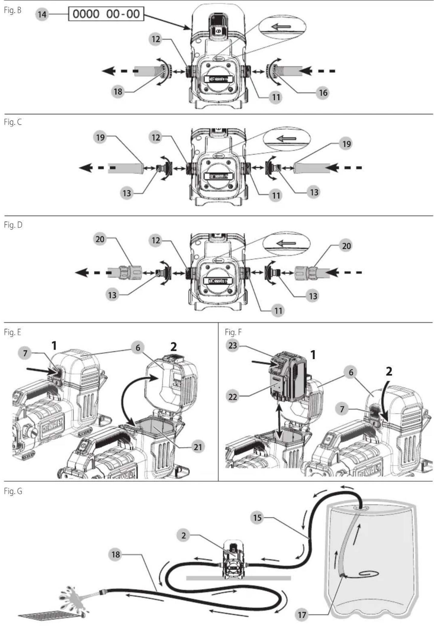
Connecting Inlet and Outlet Hoses (Fig. A–D)
WARNING: To reduce the risk of serious personal injury, turn unit off and remove the battery pack before making any adjustments or removing/installing attachments or accessories. An accidental start-up can cause injury.
WARNING: Do not reverse inlet and outlet connections. Do not allow back flow to the pump.
CAUTION: A heavy duty hose should be used for the inlet hose to prevent the hose from collapsing.
The DCE050 uses hoses with a 3/4" BSPT female fitting.
NOTE: For best results, use a short length, large diameter hoses (not included). Longer or smaller diameter hoses may affect performance and flow rate.
- Remove the two hose connection caps 10.
- For best results, apply thread sealing tape (not included) onto the hose inlet connection 11 to help create an air tight connection.
Using hoses with a 3/4" BSPT female fittings
- Thread the suction hose connection 16 clockwise onto the hose inlet connection 11. Tighten the suction hose connection 16 to the hose inlet connection 11.
NOTE: Ensure the flow of water matches the direction of flow arrow on the main housing.
-
Use a hose with a 3/4" BSPT female fitting for an outlet hose 18. Tighten the outlet hose connection 12 clockwise to the hose outlet connection 12.
-
Ensure that all hose connections are tight.
NOTE: Small leaks from the hose inlet connection will greatly reduce suction and the efficiency of the pump, and may prevent priming.
- Always disconnect the hoses after usage.
Using the optional male quick connect hose adapters
-
To connect the male quick connect hose adapters 13 to the hose inlet connection 11 and hose outlet connection 12, place the threaded end of the male quick connect hose adapter 13 onto the hose connections 11, 12.
-
Thread the connect hose adapters 13 clockwise onto the hose connections 11, 12 and tighten by hand.
NOTE: Avoid cross threading when installing the male quick connect hose adapter 13.
NOTE: Small leaks from the hose inlet connection will greatly reduce suction and the efficiency of the pump, and may prevent priming.
Push fit (Fig. C)
- With the quick connect hose adapters installed, push the hose opening 19 (not included) over the male quick connect hose adaptors 13 until secured in place.
NOTE: Ensure the flow of water matches the direction of flow arrow on the main housing.
- Always disconnect the hoses after usage.
Quick connect (Fig. D)
- With the quick connect hose adapters installed, a hose with a quick connect hose 20 (not included) can now be attached to the male quick connect hose adaptors 13. Push the quick connect hose 20 onto the male quick connect hose adaptors 13 until it clicks into place.
NOTE: Ensure the flow of water matches the direction of flow arrow on the main housing.
- Always disconnect the hoses after usage.
Installing and Removing the Battery Pack (Fig. E, F)
NOTE: For best results, make sure your battery pack is fully charged. To Install the Battery Pack
-
Press the battery port cover release button 7 and then lift up the battery port cover 6 to expose the battery port 21.
-
Align the battery pack 22 with the rails inside the battery port 21 and slide the battery pack in until the battery pack is firmly seated in the battery port 21. Ensure that the battery pack 22 does not disengage.
WARNING: Do not put your hand between the battery port cover 6 and battery port 21. If the self-closing cover is not held back your hand/finger could get crushed.
- Close the battery port cover 6. Ensure the battery port cover release button 7 is fully latched into position before starting the DCE050.
To Remove the Battery Pack
-
Press the battery port cover release button 7 and then lift up the battery port cover 6 to expose the battery pack 22.
-
Press the battery release button 23 on the battery pack 22 and firmly pull the battery pack out of battery port 21.
OPERATION
Instructions for Use
WARNING: Always observe the safety instructions and applicable regulations.
WARNING: To reduce the risk of serious personal injury, turn tool off and disconnect battery pack before making any adjustments or removing/installing attachments or accessories.
An accidental start-up can cause injury.
LED Indicator Guide
The DCE050 is equipped with a LED indicator on the on/off button 5. The section provides a list of possible LED patterns, and the causes.

NO LED
Unit is powered off. The LED indicator is constantly off.

GREEN LED
Unit is powered on. The LED indicator is constantly green.
BLINKING GREEN LED
Unit is powered on. The LED indicator is blinking green. Battery charge is low. Remove the battery and charge it.
BLINKING RED LED
Unit is powered on. The LED indicator is blinking red. The motor or battery is overloaded during operation or has reached a high temperature. Allow the DCE050 and the battery to cool down.
OPERATION (Fig. A–G)
WARNING: To reduce the risk of serious personal injury, turn unit off and remove the battery pack before making any adjustments or removing/installing attachments or accessories. An accidental start-up can cause injury.
CAUTION: Place the transfer pump in a dry location only.
CAUTION: Keep the pump inlet clean and free of any foreign objects and debris. Inspect the pump inlet, and potentially the outlet, at beginning of each use.
AUTION: After usage, wear gloves prior to removing hose fittings. Fittings may be warm.
WARNING: Pumped water is not potable water and is not safe for human or animal consumption.
WARNING: Never operate the pump without having a hose connected to both inlet and outlet connections.
The DCE050 is equipped with a thermal sensor which avoids overheating the pump. If the pump stops working and the LED indicator is blinking red (refer to LED Indicator Guide), allow the DCE050 to cool down before operating again. There is an increased likelihood of thermal shutdown when trasfering hot water.
-
Arrange the inlet and outlet hoses to ensure that there are no kinks or sharp bends.
-
Remove the two hose connection caps 10.
- Attach the inlet and outlet hoses to the transfer pump as described in the Connecting Inlet and Outlet Hoses section.
- Place the feet 3 or 4 on a dry, flat and stable surface.
- Place the inlet 17 of the suction hose 15 below the water surface.
- Secure the free ends of both hoses 17, 18 so they will not move unexpectedly when the water transfer begins.
- Install a battery pack 22 as described in the Installing and Removing the Battery Pack section.
- Press the on/off button 5 to power on the transfer pump.
- Allow at least ten seconds to purge the system of air. If the pump doesn't prime and is still drawing air after ten seconds press the on/off button 5 to turn the pump off.
AUTION: DO NOT allow the pump to run dry. Damage to the pump could occur. To help prevent pump damage, a dry pump will shut off automatically within 60 seconds. Turn the pump off and then back on to reset it.
10. The pump should be no more than 4.5 m above the inlet water source. The maximum discharge height is 13.7 m above the pump.
NOTE: If anything but clear water is accidentally pumped, flush the pump with clear water and/or a water/glycol mix (up to 60% water and 40% glycol) for at least thirty seconds.
- To stop pumping, press the on/off button 5.
- When finished pumping, remove the inlet and outlet hoses and pour any excess water from the pump.
- Remove any remaining water from the pump, run the empty pump for no more than five seconds.
- Install the two hose connection caps 10 to ensure debris does not enter the pump while in storage.
CAUTION: Freezing temperatures can cause remaining water in the pump to freeze and could damage the pump.
MAINTENANCE
Your power tool has been designed to operate over a long period of time with a minimum of maintenance. Continuous satisfactory operation depends upon proper tool care and regular cleaning.
WARNING: To reduce the risk of serious personal injury, turn tool off and disconnect battery pack before making any adjustments or removing/installing attachments or accessories. An accidental start-up can cause injury.
The charger and battery pack are not serviceable.
Please refer to the back page of this manual for service centre contact information, or visit www.2helpU.com.
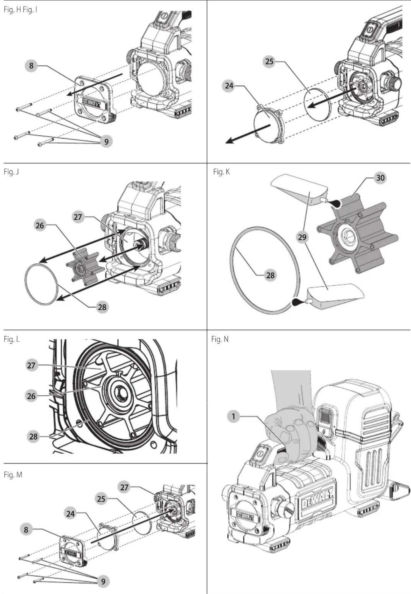
Impeller (Fig. H–M)
WARNING: To reduce the risk of serious personal injury, turn unit off and remove the battery pack before making any adjustments or removing/installing attachments or accessories. An accidental start-up can cause injury.
MUTION: Inspect the impeller for wear before each use. Clear or replace the impeller if it appears blocked or damaged.
AUTION: Always disconnect the appliance from the supply before assembling, disassembling or cleaning.
- Using a crosshead screwdriver (not supplied), remove the four impeller cover screws 9 from the impeller cover 8 by rotating them counterclockwise.
-
Lift the impeller cover from the pump housing.
-
Lift out the impeller window 24.
- Lift out the round impeller spacer 25.
- Pull the impeller 26 out from the pump housing 27.
- Pull the impeller o-ring 28 out from the pump housing.
- Inspect impeller o-ring 28 and impeller 26 for wear and damage. If there is any evidence of wear or damage, replace the impeller or gasket with:
DEWALT impeller gasket NA304884.
DEWALT impeller NA379414.
- Rinse off debris from the impeller o-ring 28 and impeller 26 with clean water and a soft brush.
- Apply a small amount (0.2-0.3 ml) of silicone grease 29 (not included) to the impeller blades 30 and the impeller o-ring 28 and then install into the pump housing 27 as shown in Fig. K, M.
- Install the round impeller spacer 25, the impeller window 24 and then the impeller cover 8 over the impeller. Insert the four impeller cover screws 9 into the impeller cover 8.
- Using a crosshead screwdriver (not supplied) tighten the four cover screws 9 clockwise until snug.
NOTE: Hand-tighten impeller cover screws. Do not use power tools or overtighten.
WARNING: Only switch the pump on if all four screws are sufficiently tightened.
Lubrication (Fig. K)
Your DCE050 when servicing them, the impeller blades 30 and the impeller o-ring requires a small amount of silicone grease.
Cleaning
WARNING: Electrical shock and mechanical hazard.
Disconnect the electrical appliance from the power source before cleaning.
WARNING: To ensure safe and efficient operation, always keep the electrical appliance and the ventilation slots clean.
WARNING: Never use solvents or other harsh chemicals for cleaning the non-metallic parts of the tool. These chemicals may weaken the materials used in these parts. Use a cloth dampened only with water and mild soap. Never let any liquid get inside the tool; never immerse any part of the tool into a liquid.
AUTION: Always disconnect the appliance from the supply before assembling, disassembling or cleaning.
Ventilation slots can be cleaned using a dry, soft non-metallic brush and/or a suitable vacuum cleaner. Do not use water or any cleaning solutions. Wear approved eye protection and an approved dust mask.
Transportation (Fig. N)
AUTION: To prevent accidental starting, always transport your tool with the batteries removed!
Storage (Fig. N)
AUTION: Always store your tool with the batteries removed! Store the tool and batteries in a cool and dry place.
CAUTION: Never store with liquid inside the pump.
CAUTION: Pump shall not be left outside during freezing weather conditions.
- Carry the DCE050 pump using the main handle 1 as shown in Fig. N.
- Store in a dry, covered location above freezing temperature.
STORE InDOORs.
To store the DCE050 pump:
- Remove the battery pack.
- Remove the inlet and outlet hoses from the pump.
- Pour out any excess water from the pump.
- Run the pump for no more than five seconds to clear out any remaining water. Freezing temperatures can cause remaining water in the pump to freeze and could damage the pump.
- Install the two hose connection caps 10.
Accessories
WARNING: Since accessories, other than those offered by DEWALT, have not been tested with this product, use of such accessories with this tool could be hazardous. To reduce the risk of injury, use only DEWALT accessories recommended for this product.
Protecting the Environment


Products/batteries are recyclable, but if marked with the crossed-out bin, they must not be disposed of with normal household waste.
Run the batteries down completely and separate them, and separate any light sources from the product if possible. It is the user's responsibility to delete personal data from the product. Then take the waste to an official waste collection centre or a participating retailer who will often accept it free of charge. Packaging should be discarded based on the marked material code. Operating and safety instructions should only be discarded once the applicable product is no longer in use. Please check with your local community/municipality for waste management guidance. For further information, visit www.2helpU.com and scan the above QR code.
TROUBLESHOOTING
WARNING: Risk of unsafe operation. Remove the battery before servicing and discharge any residual fluid. PROBLEM CaUsE CORRECTION
| Motor does not start. | Battery pack not installed properly. Check battery pack installation. | |
| Battery pack not charged. Check battery pack charging requirements. | ||
| On/off switch is in the OFF position. Press the on/off switch to the ON position. | ||
| Pump does not reach high pressure. Impeller cover is not sealed/tight. Ensure impeller glass is seated correctly.Ensure impeller gasket is seated correctly.Hand tighten the four impeller cover screws. | ||
| Pump turns off. | Not enough inlet water supply. | Adjust the intake line stays fully covered with liquid. Check hose for leaks and kinks. |
| Pump is sucking air. Check that hoses and fittings are air tight. Turn the pump OFF and then back on. | ||
| Water inlet clogged. To unclog, rinse off with clean water. | ||
| Impeller is locked in place. Blow out or remove debris. | ||
| Battery pack not charged. Check battery pack charging requirements. | ||
| Hose connection leaks. | Loose fittings. | Tighten fittings. |
| Missing/worn rubber washer. | Replace washer in hose adapter. | |
| Pump does not self prime. | Loose fittings. | Tighten fittings. |
| Line intake is not fully submerged. | Adjust the line intake so that it stays fully covered with liquid.Allow more time for pump to prime. | |
| Pump is excessively noisy. | Pump is sucking air. Check that hoses and fittings are air tight. | |
| Water leaks from pump. | Loose fittings. | Check that all fittings are tight. |
| Water seals are damaged or worn. | Contact DEWALT local dealer or authorized service center. | |
| Motor buzzes but fails to run. | Impeller is locked in place. | Inspect/replace with new impeller. See Impeller section. |
| Pump was not used for long periods. | Inspect/replace impeller or contact DEWALT local dealer or authorized service center. | |
Vice President of Engineering Europe
WAARSCHUWING: Lees alle
WAARSCHUWING: RISICO OP INJECTERING OF LETSEL.
Vice President of Engineering Europe
Vice President of Engineering Europe