AS88 - Hand blender Midas - Free user manual and instructions
Find the device manual for free AS88 Midas in PDF.

User questions about AS88 Midas
0 question about this device. Answer the ones you know or ask your own.
Ask a new question about this device
Download the instructions for your Hand blender in PDF format for free! Find your manual AS88 - Midas and take your electronic device back in hand. On this page are published all the documents necessary for the use of your device. AS88 by Midas.
USER MANUAL AS88 Midas
Dual HyperMAC to 8 Port Dual Redundant AES50 Converter
2 AS99Quick Start Guide 3
EN
ES
EN Safety Instructions
Please read these safety instructions carefully and pay
close attention to any warning symbols displayed
on the product and their related safety information
Terminals marked with this symbol carry electrical current of sufficient magnitude to constitute risk of electric shock. Use only high-quality professional speaker cables with TS or twist-locking plugs pre-installed. All other installation or modification should be performed only by qualified personnel.
This symbol, wherever it appears, alerts you to the presence of unirradiated dangerous voltage inside the enclosure voltage that may be sufficient to constitute a risk of shock.
This symbol, wherever it appears, alerts you to important operating and maintenance instructions. Please read full manual.
Caution To reduce the risk of electric shock, do not remove the top cover (or the rear section). No user serviceable parts inside. Refer servicing to qualified personnel.
Caution To reduce the risk of fire or electric shock, do not expose this appliance to rain and moisture. The apparatus shall not be exposed to dripping or splashing liquids and no objects filled with liquids, such as vases, shall be placed on the apparatus.
Caution These service instructions are for use by qualified service personnel only. To reduce the risk of electric shock do not perform any servicing other than that contained in the operation instructions. Repairs have to be performed by qualified service personnel.
Warning Please refer to the information on the exterior of bottom enclosure for electrical and safety information before installing or operating the device.
Warning To prevent possible hearing damage, do not listen at high volume levels for long periods. As a guide to setting the volume level, check that you can still hear your own voice, when speaking normally while listening with the headphones.
-
Read and keep these instructions. Need all warnings and follow all instructions.
-
Do not use this apparatus near water (if applicable). Clean only with dry cloth.
-
Do not block ventilation openings (if applicable). Do not install in a confined space. Install only according to manufacturer's instructions.
-
Do not install near any heat sources such as radiators, heat registers, stoves or other apparatus (including amplifiers) that produce heat. Do not place naked flame sources, such as lighted candles, on the apparatus.
-
Do not defeat the safety purpose of the polarized or grounding type plug. A polarized plug has two blades with one wider than the other only for USA and Canada. A grounding-type plug has two blades and a third grounding proing. The wide blade or the third proing are provided for your safety. If the provided plug does not fit into your outlet, consult an electrician for replacement of the obsolete outlet.
-
(if applicable) Protect the power cord from being walked on or pinched particularly as plugs, convenience receptacles, and the point where they exit from the apparatus.
-
Use only attachments and accessories recommended by the manufacturer.
-
Use only specified carts,

stands, tripods, brackets, or tables specified by the manufacturer, or sold with the apparatus (if applicable). When a n when moving the nation to avoid injury
-
Unplug during storms, or if not in use for a long period.
-
Refer all servicing to qualified service personnel. Servicing is required when the apparatus has been damaged in any way, such as power supply cord or plug is damaged, liquid has been spilled or objects have fallen into the apparatus, the apparatus has been exposed to rain or moisture, does not operate normally, or has been dropped.
-
(If applicable) The apparatus with protective earthing terminal shall be connected to a MAIRS socket outlet with a protective earthing connection.
-
(If applicable) Where the MAINS plug or an appliance coupler is used as the disconnect device, the disconnect device shall remain readily operable.
-
Internal/External Voltage Selectors (if applicable): Internal or external voltage selector switches, if any, should only be reset and re-equipped with proper plug or alternative voltage by a qualified service technician. Do not attempt to alter this yourself.
-
Class II Wiring (if applicable): To reduce the risk of electric shock, the external wiring connected to the terminals with "Class II Wiring" requires Class II wiring installed by an instructed person or the use of ready-made leads or cards.
-
Operating temperature range 5^ to 45^ C ( 41^ to 113^ F).
LEGAL DISCLAIMER
The information contained in this Quick Start Guide and accompanying manual is provided for general guidance only. While every effort has been made to ensure the accuracy and reliability of the content at the time of publication, Music Tribe Global Brands Ltd. ("Music Tribe") makes no representations or warranties, express or implied, as to the completeness, accuracy, or suitability of the information, descriptions, illustrations, or technical specifications herein.
Music Tribe accepts no liability for any direct, indirect, incidental, or consequential loss or damage arising from reliance on the information contained in this document, including but not limited to loss of data, income, profits, or business opportunities. Use of the product remains the sole responsibility of the user.
Product features, design, specifications, and visual representations may be updated or modified without prior notice in the interest of continuous product improvement.
All third-party trademarks referenced in this guide are the property of their respective owners. Midias, Klark Teknik, Lab Gruppen, Lake, Tannoy, Turbosund, TC Electronic, TC Holicon, Behringer, Bugera, Aston Microphones, and Coolaudio are trademarks or registered trademarks of Music Tribe Global Brands Ltd. © 2025 Music Tribe Global Brands Ltd. All rights reserved. No part of this document may be reproduced, transmitted, or used in any form or by any means without prior written permission from Music Tribe.
LIMITED WARRANTY
For the terms, conditions, and limitations applicable to your product, including coverage, exclusions, and the duration of the limited warranty, please refer to the complete Music Tribe Limited Warranty Policy, available online at community.musictribe.com/support Please retain your proof of purchase, as it may be required for warranty service.
BESCHRÄNKTE GARANTIE
- If applicable! As with all small batteries, the batteries used with this product should be kept away from small children who still put things in their mouths. If they are swallowed, promptly call your local poison control center for treatment information.
• If applicable! Always remove battery if consumed or if product is to be left unused for a long time
• (If applicable) Do not mix old and new batteries, different brands or types of batteries, such as alkaline, carbon-zinc, or rechargeable batteries. (If one more batteries used)
- [If applicable] Clean the battery contacts and also these of the device prior to battery installation
• [II applicable] Replacement of a battery with an incorrect type that can defeat a saleguard! Replace only with the same or equivalent type
• [If applicable] Replace all batteries of a set at the same time, ensure the batteries are installed correctly with the regard to polarity (+ and -)
- Disposal of a battery into line or a hot oven, or mechanically crushing or cutting of a battery, that can result in an explosion
• Leaving a battery in an extremely high temperature surrounding environment that can result in an explosion or the leak of flammable liquid or gas.
- 6 battery subjected to extremely low air pressure that may result in an explosion or the leakage of flammable liquid or gas.
- Attention should be drawn to the environmental aspects of battery disposal. Do RDT disburse batteries in household trash or irrigated
- Batteries (battery pack or batteries installed) shall not be exposed to excessive heat such as sunshine, fire or the life
WARNING
- INGESTION HAZARDS: This product contains a button roll or can battery. - DEATH or serious injury can occur if inspected
A. S. A. B. C. D. E. F. G. H. I. J. K. L. M. N. O. P. Q. R. S. T. U. V. W. X. Y. Z. A.
Internal clinical visits 1/8/13/2005
Seek immediate medical attention if a battery is suspected to be usual or inserted inside any part of the body


Advertencia
Thank you for purchasing the AS88 HyperMAC to 8 Port Dual Redundant AES50 Converter.
Features
- Dual redundant HyperMAC to 8 redundant AES50 SMAC converter
• Up to 192 bidirectional channels at 96 kHz - Dual redundant auto-ranging universal switch mode power supply
- Compact and rugged design
- 2u rackmountable
- Clocked from AES50 or HyperMAC ports
- Connection redundancy status available from connected console indicating cable state
- Industry standard connectors used for AES50 ports and copper snake connection
- Industry standard Dual fibre connectors used for optical fibre snake connection
About this QSG/manual
This is the operation manual for the AS88. This manual is intended to help get your unit installed and in operation as quickly as possible by giving you unpacking, installation, connection, setting up and operating instructions.
AS88 Getting started
EN Step 2: Getting started
Unpacking
Carefully unpack your AS88 unit. Then, inspect the unit carefully for any signs of damage that may have occurred during transit and notify the courier immediately if you discover any. Check the contents of your AS88 equipment package. If there are any parts missing, incorrect or faulty, please contact your local distributor or Midas support.
Inside this box, you should find the following items:
• AS88
- 2 x IEC power cables
- Quick Start Guide
Please retain the original packing in case you should need to return the equipment to the manufacturer or supplier, or transport or ship the unit later.
Installation
Before installing and operating this equipment, make sure it is correctly connected to the protective earth conductor of the mains voltage supply socket outlet through each mains lead. Ideally a cool area is preferred, away from power distribution equipment or other potential sources of interference. Do not install the equipment in places of poor ventilation. Do not install this equipment in a location subjected to excessive heat, dust or mechanical vibration.
Allow for adequate ventilation around the equipment, making sure that its fans and vents are not obstructed. Whenever possible, keep the equipment out of direct sunlight.
Power
The internal power supplies are of the switch mode type that automatically senses the incoming mains voltage and will work where the nominal voltage is in the range 100 VAC to 240 VAC. The correct power leads for your country are supplied with the unit. The equipment should only be plugged into the mains outlets using the supplied leads. Make sure the plug fitted on the supplied mains cable is securely fitted to the mains IEC connector on the unit. When fitting or removing a plug, always hold the plug itself and never use the cable, as this may damage it. Never insert or remove an electric plug with wet hands.
Connecting up
The AS88 unit uses the following leads and connectors:
HyperMAC Connections:
RJ45 copper or Multimode optical fiber
AES50 Connections:
RJ45 Copper
Power Connection:
Standard IEC C13 cables.
HyperMAC and AES50
HyperMAC is a proprietary system for distributing digital audio. Its features include 192 channel bi-directional feeds at 96 kHz sampling rate which can be sent over copper Cat Se;
or 50,125 μm optical fiber.
AESSO is an Industry standard digital audio connection protocol which allows 24 channel bidirectional data flow at 95 kHz.
The Midas knowledge base contains more information about suitable cables; and is updated when specs change: https://community.musictribe.com/kba/article/KA-09432/Midas
18 A689
Quick Star Guide
19
AS88 Controls
EN Step 3: Controls

text_image
Diagram of an electronic device rear panel with labeled components and internal components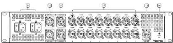
text_image
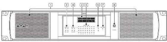
Diagram of a multi-chamber industrial control panel with labeled ports and connectionsFront Panel
-
Ventilation grills - keep clear of obstruction.
-
Display – shows the AS-88's IP address, the status of the AES50 ports, clock status, sample rate and optical type in use.
-
Snake X status LEDs – show the status of the connected snake; and whether copper cable or optical fibre is in use.
-
Snake Y status LEDs — show the status of the connected snake; and whether copper cable or optical fibre is in use.
-
AESSO audio status LEDs — show the status of each AESSO port. X & Y status LEDs show if a connection is present per AESSO Port.
-
PSU 1 & 2 LEDS - shows if power is present on the rear panel IEC inputs [9].
-
Ethernet control status LED - Shows the current activity on the ETHERNET CONTROL port (13).
-
Power on indicator, which lights in blue when power is present. The AES50 LEDs show status as follows:
- Green lit – link is made and in standby mode.
- Green pulsing - link is active and selected.
- Green off - link is down.
- Red lit – link is down or there is a link error.
- Red flashing - attempting to synchronize clock through this port.
- Red off - link is made, no connection errors.
The HyperMAC LEDs show status as follows:
- Green lit – link is made and in standby mode.
- Green pulsing – link is active and selected.
- Green flashing – link is down but cable is connected.
- Green off - link is down.
- Red In - link is down or there is a link error.
- Red flashing – attempting to sync to an external clock source.
- Red off - link is made, no connection errors.
Rear Panel
-
Dual redundant IEC power sockets and on/off switches.
-
Dual redundant HyperMAC optical I/O ports.
-
Dual redundant HyperMAC copper I/O ports.
-
AES50 U/O ports, 8 on X feed and B on Y feed.
-
Ethernet socket for connection to control PC.
-
Factory reset button.
Note that for dual redundancy to work correctly optical and copper should not be mixed on X and Y. Use two optical or two copper only.
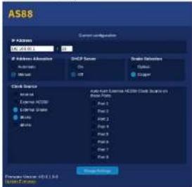
Software Control/Setup
text_image
AS88 P-Case SMCP Server SMD Server Grid Server Cloud Server External AS88 External Space Windows MSA Auto-log Server AS88 (Cloud Server) Windows Port 2 Port 3 Port 1 Port 4 Port 5 Port 6 System Server System Server System Server System Server System ServerThe AS88 is software configurable via its onboard webpage. To access this connect a PC or Mac to the Ethernet Control port [13], set a suitable IP address and subnet mask for your computer's ethernet interface, then open your web browser to access the AS88 configuration page. The window illustrated above will open and allow you to:
- Set the IP address of the 4588. This should be 192.168.80.1 for snake 1 connection; 192.168.81.1 for snake 2.
- Set whether IP address allocation is manual or automatic. If Automatic is selected then you will not be able to type an address into the first field. For HD use the address should always be set to manual.
- Select whether DHCP server is on or off. For HD use this should always be set to off.
- Select whether the snake in use is copper or optical fibre. For HD use the snake settings will be automatically changed by the console configuration.
- Select the master clock source. If AES50 is selected you also have the option to auto-hunt for a clock on any selected AES50 port. For HD use the snake settings will be automatically changed by the console configuration.
- Set the sample rate to 96 kHz.
The current firmware version is also displayed; and can be updated from this page or the device updater direct from the console if necessary.
20
Quick Star Guide 21
AS88 Usage Examples
EN Step 4: Usage Examples
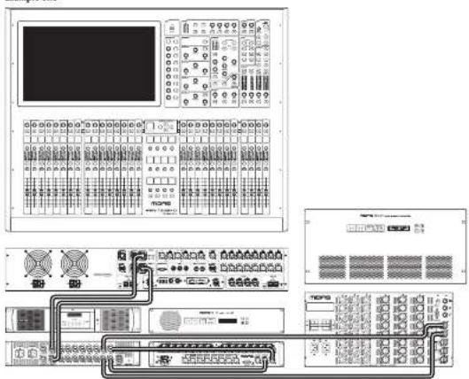
Example One
text_image
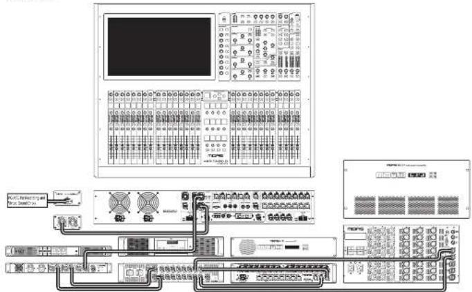
Technical diagram of a control panel with labeled components and connected interfaces for system monitoring or data processing.In this example a Heritage D console is linked to the AES81 via dual redundant copper snake connections. Two detailed AES50 outputs then feed a DL153 Audio 1Q unit, which in this instance could be used to convert the AES50 digital feed from the Heritage D to analog for PA use; and a DL231 Audio Input Splitter, which might be used as a stage box to pre-amplify and digitize up to 24 microphone and/or DI connection on stage as well as providing 48 V phantom power and analog outputs if required.
When connected to an HD Series console the snake connection should have an IP address of 192.158.80.1.
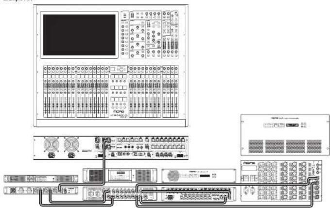
Example Two
text_image
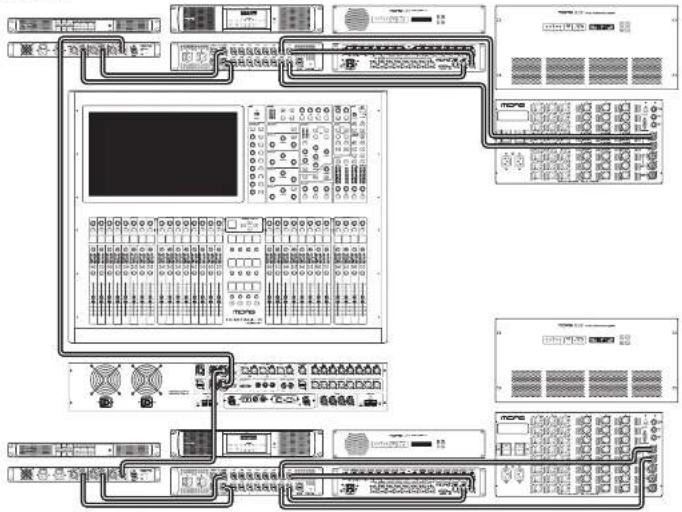
Technical diagram of a server rack system with labeled components and connectionsIn this example the Heritage D has a single copper snake connection to an AS80 Dual Redundant HyperIAC unit; which then makes a dual redundant copper connection to the AS88. As in example one the AS88 has two dualled WESSD outputs that feed a DL153 Audio 10 unit and a DL231 Audio System Input Splitter. When connected to an HD Series console the snake 1 connection should have an IP address of 192.168.80. I; and the snake 2 connection should have IP of 192.168.81.
EN
22 AS80Quick Start Guide 23
AS88 Usage Examples
Example Three
text_image
Technical diagram of a multi-panel electronic control system with labeled modules and connectionsThis example has the same connection chain as example two; with the addition of the second copper snake connection being linked to a Midas Cobalt which converts the audio to a USB C feed suitable for connection to a PC or Mac for recording and monitoring.
EN
Example Four
flowchart
graph TD
    A["输入设备"] --> B["模拟器"]
    B --> C["数据采集模块"]
    C --> D["监控面板"]
    D --> E["数据传输模块"]
    E --> F["数据存储模块"]
    F --> G["数据处理模块"]
    G --> H["数据输出模块"]
    H --> I["系统控制单元"]
    I --> J["数据采集与监控"]
    J --> K["数据存储与监控"]
    K --> L["数据处理与监控"]
    L --> M["数据输出与监控"]
    M --> N["系统控制单元"]
    N --> O["数据采集与监控"]
    O --> P["数据存储与监控"]
    P --> Q["数据处理与监控"]
    Q --> R["数据输出与监控"]
In this example the entire chain used in example two is dualled, with each component except the Heritage D being duplicated. Set the IP addresses as in example 2.
24 AS89Quick Start Guide 25
AS88 Introducción
text_image
Diagram of a multi-chamber industrial control panel with labeled ports and connectionsPanel Frontal
text_image
Ejemplo Dos I/O I/O I/O I/O I/O I/O I/O I/O I/O I/O I/O I/O I/O I/O I/O I/O I/O I/O I/O I/O I/O I/O I/O I/O I/O I/O I/O I/O I/O I/O I/O I/O I/O I/Otext_image
Technical diagram of a multi-panel electronic control system with labeled modules and connectionsflowchart
graph TD
    A["Programs"] --> B["Control Panel 1"]
    A --> C["Control Panel 2"]
    A --> D["Control Panel 3"]
    A --> E["Control Panel 4"]
    A --> F["Control Panel 5"]
    A --> G["Control Panel 6"]
    A --> H["Control Panel 7"]
    A --> I["Control Panel 8"]
    A --> J["Control Panel 9"]
    A --> K["Control Panel 10"]
    A --> L["Control Panel 11"]
    A --> M["Control Panel 12"]
    A --> N["Control Panel 13"]
    A --> O["Control Panel 14"]
    A --> P["Control Panel 15"]
    A --> Q["Control Panel 16"]
    A --> R["Control Panel 17"]
    A --> S["Control Panel 18"]
    A --> T["Control Panel 19"]
    A --> U["Control Panel 20"]
    A --> V["Control Panel 21"]
    A --> W["Control Panel 22"]
    A --> X["Control Panel 23"]
    A --> Y["Control Panel 24"]
    A --> Z["Control Panel 25"]
text_image
Diagram showing labeled components of a device panel with numbered indicators and internal display
text_image
Diagram of a multi-chamber industrial control panel with labeled ports and connectionsFrontplatte
text_image
AS88 Current configuration IF Network 0.0123.0.1 Network Address Network Network Server On On Show Settings Open Copy Data Server External Audio External Audio Work Work Auto-Text External Audio CLK Selection Base Path Base 1 Base 2 Base 3 Base 4 Base 5 Base 6 Base 7 Base 8 End Subnet Forward Work: No. 1, 2, 3, 4, 5, 6, 7, 8, 9, 10, 11, 12, 13, 14, 15, 16, 17, 18, 19, 20, 21, 22, 23, 24, 25, 26, 27, 28, 29, 30, 31, 32, 33, 34, 35, 36, 37, 38, 39, 40, 41, 42, 43, 44, 45, 46, 47, 48, 49, 50, 51, 52, 53, 54, 55, 56, 57, 58, 59, 60, 61, 62, 63, 64, 65, 66, 67, 68, 69, 70, 71, 72, 73, 74, 75, 76, 77, 78, 79, 80, 81, 82, 83, 84, 85, 86, 87, 88, 89, 90, 91, 92, 93, 94, 95, 96, 97, 98, 99, 100text_image
Technical diagram of a multi-panel electronic control system with labeled modules and connectionsCables standard IEC C13.
HyperMAC et AES50
text_image
Diagram of a device rear panel with numbered components and internal display panel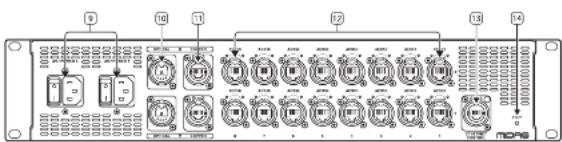
text_image
Diagram of a multi-chamber industrial control panel with labeled ports and indicator lightsPanneau Avant
text_image
AS88 Current configuration P System AS88.01 P Address Allocation Automatic Multi SMCP Server On Off Scale Detection Open Open Clock Service External AS550 External State Mobile Auto-Net External AS550 Clock Service Internal System Part 1 Part 2 Part 3 Part 4 Part 5 Part 6 Part 7 Part 8 Display Settings Forward Version: HDLL-1.0.0 Model: Modeltext_image
Example Deux NCPB6 NCPB6 NCPB6 NCPB6 NCPB6 NCPB6 NCPB6 NCPB6 NCPB6 NCPB6 NCPB6 NCPB6 NCPB6 NCPB6 NCPB6 NCPB6 NCPB6 NCPB6 NCPB6 NCPB6 NCPB1 NCPB1 NCPB1 NCPB1 NCPB1 NCPB1 NCPB1 NCPB1 NCPB1 NCPB1 NCPB1 NCPB1 NCPB1 NCPB1 NCPB1 NCPB1 NCPB1 NCPB1 NCPB1 NCPB1 NCPB2 NCPB2 NCPB2 NCPB2 NCPB2 NCPB2 NCPB2 NCPB2 NCPB2 NCPB2 NCPB2 NCPB2 NCPB2 NCPB2 NCPB2 NCPB2 NCPB2 NCPB2 NCPB2 NCPB2 NCPB3 NCPB3 NCPB3 NCPB3 NCPB3 NCPB3 NCPB3 NCPB3 NCPB3 NCPB3 NCPB3 NCPB3 NCPB3 NCPB3 NCPB3 NCPB3 NCPB3 NCPB3 NCPB3 NCPB4 NCPB4 NCPB4 NCPB4 NCPB4 NCPB4 NCPB4 NCPB4 NCPB4 NCPB4 NCPB4 NCPB4 NCPB4 NCPB4 NCPB4 NCPB4 NCPB4 NCPB5 NCPB5 NCPB5 NCPB5 NCPB5 NCPB5 NCPB5 NCPB5 NCPB5 NCPB5 NCPB5 NCPB5 NCPB5 NCPB5 NCPB5 NCPB5 NCPB5 NCPB5 NCPB5 NCPB5 NCPB6 NCPB6 NCPB6 NCPB6 NCPB6 NCPB6 NCPB6 NCPB6 NCPB6 NCPB6 NCPB6 NCPB6 NCPB6 NCPB6text_image
Technical diagram of a multi-panel electronic control system with labeled modules and connectionstext_image
Diagram of a device rear panel with labeled components and internal display panel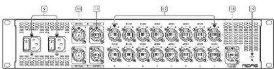
text_image
Diagram of a multi-chamber industrial control panel with labeled ports and indicator lightsPannello Frontale
text_image
AS8 F IP Address F IP Address Address SNCP Server Scale Selection Open Copper Check Server Internal External Server Control Server Water Other Selected Server (SIP) (Check Server) Base Party Part 1 Part 2 Part 3 Part 4 Part 5 Part 6 Part 7 Part 8 System System System Systemtext_image
Technical diagram of a multi-panel electronic control system with labeled modules and connectionsStandard IEC C13 kabels.
HyperMAC en AES50
NL Stap 3: Bediening
text_image
Diagram of a device rear panel with labeled components and internal layout, showing numbered slots and control buttons.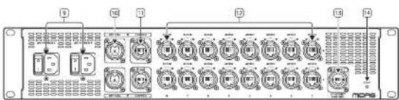
text_image
Diagram of a multi-chamber industrial control panel with labeled ports and connectionsVoorpaneel
text_image
Technical diagram of a multi-chamber electronic control module with labeled modules and connectionstext_image
Technical diagram of a power grid control system with labeled components and connectionstext_image
Technical diagram of a multi-panel electronic control system with labeled modules and connectionsStandardowe kable IEC C13.
HyperMAC i AES50
text_image
Diagram of a device rear panel with labeled components and internal layout, showing numbered slots and control buttons.
text_image
Diagram of a multi-chamber industrial control panel with labeled ports and connectionsPanel Przedni
text_image
Technical diagram of a network equipment rack with labeled components and connectionstext_image
Technical diagram of a PLC rack with labeled components including control panels, drive dials, and PLCstext_image
Technical diagram of a power grid control system with labeled components and connectionsflowchart
graph TD
    A["PLC Module"] --> B["Control Panel 1"]
    A --> C["Control Panel 2"]
    A --> D["Control Panel 3"]
    A --> E["Control Panel 4"]
    A --> F["Control Panel 5"]
    A --> G["Control Panel 6"]
    A --> H["Control Panel 7"]
    A --> I["Control Panel 8"]
    A --> J["Control Panel 9"]
    A --> K["Control Panel 10"]
    A --> L["Control Panel 11"]
    A --> M["Control Panel 12"]
    A --> N["Control Panel 13"]
    A --> O["Control Panel 14"]
    A --> P["Control Panel 15"]
    A --> Q["Control Panel 16"]
    A --> R["Control Panel 17"]
    A --> S["Control Panel 18"]
    A --> T["Control Panel 19"]
    A --> U["Control Panel 20"]
    A --> V["Control Panel 21"]
    A --> W["Control Panel 22"]
    A --> X["Control Panel 23"]
    A --> Y["Control Panel 24"]
    A --> Z["Control Panel 25"]
text_image
Diagram of a device rear panel with numbered components and internal display panel, likely for electronics or control system labeling.
text_image
Diagram of a multi-chamber industrial control panel with labeled ports and indicator lightsPainel Frontal
text_image
AS88 Current configuration P System AS88.01 P Address Allocation Address Address Mode SMCP Server Grid Selection Open Open Clock Service External AS550 External State External ATM Auto-Net External AS550 Clock Service Internal Part 1 Part 2 Part 3 Part 4 Part 5 Part 6 Part 7 Part 8 Storage Settings Forward Version: HDLL-1.0.0 Model: Modeltext_image
Technical diagram of a power grid control system with labeled components and connectionstext_image
Technical diagram of a multi-chamber industrial control panel with labeled modules and connectionstext_image
Technical diagram of a multi-panel electronic control system with labeled modules and connectionstext_image
Diagram of a device rear panel with numbered components and internal display panel, likely for electronics or control system labeling.
text_image
Diagram of a multi-chamber industrial control panel with labeled ports and indicator lightsFront Panel
text_image
Technical diagram of a network equipment rack with labeled components and connected cablestext_image
Technical diagram of a server rack system with labeled components and connectionstext_image
Technical diagram of a multi-panel electronic control system with labeled modules and connectionstext_image
Diagram showing labeled components of a device or module with numbered pins and internal display panel
text_image
Diagram of a multi-chamber electronic device with labeled ports and connectorsフロントパネル
text_image
Technical diagram of an electronic control panel with labeled modules and wiring connectionstext_image
Technical diagram of a multi-chamber industrial control panel with labeled modules and connectionstext_image
Technical diagram of a multi-panel electronic control system with labeled modules and connectionstext_image
Diagram of a device rear panel with labeled ports and internal components, showing connections between ports 1 through 8.
text_image
Diagram of a multi-chamber electronic device with labeled ports and connectors前面板
- 通风格相,保持通风口清洁。
text_image
Technical diagram of a multi-chamber electronic control panel with labeled modules and connectionstext_image
Technical diagram of a multi-chamber industrial control panel with labeled modules and connectionstext_image
Technical diagram of a multi-panel electronic control system with labeled modules and connections| Architecture | |
| HyperMAC / AFSSO Converter 2 In / 16 Out (Dual redundancy) | |
| Channels 192 at 96 MHz | |
| Connectivity | |
| Power switches: 2 x socket on rear panel | |
| Power Inlets: 2 x IEC C13 on rear panel | |
| Power Indicator Blue LED on front panel | |
| Inputs | |
| Hyper MAC Optical 2 x standard connector on rear panel | |
| Hyper MAC Copper 2 x standard connector on rear panel | |
| Ethernet R45 connector on rear panel | |
| Outputs | |
| AFSSO 16 x IEC5 socket on rear panel | |
| Controls | |
| Factory Reset Pumbation on rear panel | |
| Display | |
| 2 x 20 character | |
| LEDs | |
| Snake X status: 2 x green / 2 x red | |
| Snake Y status: 2 x green / 2 x red | |
| PSU status: 2 x green / 2 x red | |
| AFSSO status | 16 x green / 16 x red |
| Ethernet status | 1 x green |
| Power Requirements | |
| Voltage | 120 - 240 V 50.765 Hz AG |
| Power consumption | 2 x 25 W maximum draw (Dual redundancy) |
| Physical | |
| Standard Operating Temperature | 3°C - 45°C (11°F - 113°F) |
| Dimensions: 14 x 14" x D; | 85 x 440 x 483 mm (3.46 x 12.32 x 19.01") |
| Weight | 6.59 kg (14.51 lb) |
技术参数
EN Other important information
ES
EN Important information
1. Product Registration
To ensure optimal service and support, we encourage you to register your Music Tribe product immediately after purchase at musictric.com. Registration allows us to provide faster and more efficient assistance in the event of a service request or warranty claim. It also ensures that you receive important product updates, safety notices, and documentation relevant to your product.
During registration, you will also have access to the full terms and conditions of our Limited Warranty.
Please note that warranty coverage and consumer rights may vary by country or jurisdiction. Refer to the terms applicable in your region at the time of registration or via our support portal.
IT
- Technical Support and Malfunctions If you experience a malfunction or secure assistance, and a Music Tribe Authorized Reseller is not available in your area, please refer to the list of Authorized Fulfillers available under the "Support" section at musictribe.com.
If your country is not listed, we recommend using our Online Support resources as a first step, which may help resolve your issue without the need for a return. For warranty-related matters, please ensure you submit an online warranty claim before returning the product. Unauthorized returns or unregistered claims may result in processing delays or denial of warranty coverage.
3. Unauthorized Repairs and Modifications
To preserve warranty coverage, do not open, disassemble, or attempt to repair the product yourself. Repairs or modifications performed by unauthorized persons or service centers will void the warranty and may compromise product safety or performance.
Before connecting your unit to a power source, ensure that the input voltage matches the rating indicated on your product. Incorrect voltage may cause permanent damage and void the warranty.
If the fuse requires replacement, only use fuses of the same type and rating. Use of incorrect fuses may create a fire or safety hazard and will invalidate all warranty protection.
- Proper Use and Environment Ensure that your Music Tribe product is used in accordance with the product manual and within the recommended operating conditions. Exposure to excessive moisture, dust, heat, or impact may result in malfunction and void the warranty.
ES
Other important information

Ważna informacja

Correct disposal of this product: This symbol indicates that this product must not be disposed of with household waste, according to the WEEE Directive (2012/19/EU) and your national law. This product should be taken to a collection center licensed for the recycling of waste electrical and electronic equipment (EEF). The mishandling of this type of waste could have a possible negative impact on the environment and human health due to potentially hazardous substances that are generally associated with EEF. At the same
time, your cooperation in the correct disposal of this product will contribute to the efficient use of natural resources. For more information about where you can take your waste equipment for recycling, please contact your local city office, or your household waste collection service.
Responsible Party Name: Empower Tribe Innovations
US Inc.
Address: 901 Grier Dr. Las Vegas, NV, 89119, USA
Email Address: legal@musictribe.com
AS88
This equipment has been tested and found to comply with the limits for a Class A digital device, pursuant to part 15 of the FCC Rules. These limits are designed to provide reasonable protection against harmful interference when the equipment is operated in a commercial environment. This equipment generates, uses, and can radiate radio frequency energy and, if not installed and used in accordance with the instruction manual, may cause harmful interference to radio communications. Operation of this equipment in a residential area is likely to cause harmful interference in which case the user will be required to correct the interference at his own expense.
This equipment complies with Part 15 of the FCC rules. Operation is subject to the following two conditions:
(1) this device may not cause harmful interference, and (2) this device must accept any interference received. Including interference that may cause undesired operation.
Warning: Operation of this equipment in a residential environment could cause radio interference.
Important Information: Changes or modifications to the equipment not expressly approved by Music Tribe can void the user's authority to use the equipment.
CE
Hereby, Music Tribe declares that this product is in compliance with Directive 2014/35/EU, Directive 2014/30/EU, Directive 2011/65/EU and Amendment 2015/863/EU, Directive 2012/19/EU, Regulation S19/2012 REACH SVHC and Directive 1907/2006/EC.
Full text of EU DoC is available at https://community.musictribe.com/
EU Representative: Empower Tribe Innovations DE GmbH Address: Otto-Brenner-Strasse 4a, 47877 Willich, Germany
UK Representative: Empower Tribe Innovations UK Ltd. Address: 5 Brindley Road Old Trafford, Manchester, United Kingdom, M16 SUN