HD96 - Hand blender Midas - Free user manual and instructions
Find the device manual for free HD96 Midas in PDF.

| Product type | Digital mixing console |
| Brand | Midas |
| Model | HD96-24 |
| Input channels | 144 (flexi simultaneous) |
| Output channels | 96 aux, 24 matrix, stereo bus, mono bus |
| Audio processing | 64-bit floating point |
| Sampling frequency | 96 kHz |
| A/D and D/A converter | 24-bit, 128-bit oversampling |
| Touchscreen | 21 inches, 1920 x 1080 pixels, 10-point multi-touch |
| Motorized faders | 28 (8+8+8+4) |
| Analog input/output connectivity | 8 XLR inputs, 8 XLR outputs |
| Digital connectivity | AES50 (4 ports), HyperMAC (2 fiber), Ultranet (2 ports) |
| Power supply | 2 x 100-240 V, 50/60 Hz, 2 x 650 W |
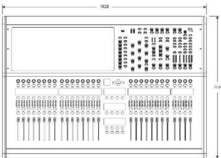
| Dimensions (without casters) | 352 x 1028 x 719 mm |
| Weight (without casters) | 43.2 kg |
| Weight (with casters) | 147 kg |
| Bluetooth | Version 4.0, range 30 m |
| Wi-Fi | Dual band 2.4/5 GHz |
| Warranty | 10 years Midas |
| Maintenance | Clean with a dry cloth; do not expose to moisture |
| Safety | Grounding mandatory; presence of dangerous button batteries |
| Possible extension | 2 CM-1 slots for additional cards |
Frequently Asked Questions - HD96 Midas
User questions about HD96 Midas
0 question about this device. Answer the ones you know or ask your own.
Ask a new question about this device
Download the instructions for your Hand blender in PDF format for free! Find your manual HD96 - Midas and take your electronic device back in hand. On this page are published all the documents necessary for the use of your device. HD96 by Midas.
USER MANUAL HD96 Midas
natural_image
Top-down schematic of a music instrument with control panels, stage, and audio equipment (no readable text or symbols)HD96-24-CC-TP
Live Digital Console Control Centre with 144 Input Channels, 120 Mix Buses, 96 kHz Sample Rate, 21" Touch Screen and Touring Grade Road Case
2 Quick Sari Gu de 3HD05-24C-IP
EN
ES
EN Important Safety Instructions

Terminals marked with this symbol carry electrical current of sufficient magnitude to constitute risk of electric shock. the only high quality professional speaker tables with 15" TS or twist-locking plugs pre installed. All other installation or modification should be performed only by qualified personnel.
This symbol, wherever it appears, alerts you to the presence of uninsulated dangerous voltage inside the enclosure - voltage that may be sufficient to constitute a risk of shock.
This symbol, wherever it appears, alerts you to important operating and maintenance instructions in the accompanying literature. Please read the manual.
Caution To reduce the risk of electric shock, do not remove the top cover (or the rear section). No user serviceable parts include. Refer servicing to qualified personnel.
Caution To reduce the risk of fire or electric shorts, do not expose this appliance to rain and moisture. The apparatus shall not be exposed to dripping or splashing liquids and no objects filled with liquids, such as wares, shall be plated on the apparatus.
Caution These service instructions are for use by qualified service personnel only. To reduce the risk of electric shock do not perform any servicing other than that contained in the operation instructions. Repairs have to be performed by qualified service personnel.
- Read these instructions.
- Keep these instructions.
- Here all warnings.
- Follow all instructions.
- Do not use this apparatus near water.
- Clean only with dry cloth.
- Do not block any ventilation openings, install in accordance with the manufacturer's instructions.
-
Do not install near any heat sources such as radiators, heat registers, stoves, or other apparatus including amplifiers that produce heat.
-
Do not defeat the safety purpose of the polarized or grounding-type plug. A polarized plug has two blades with one wider than the other. A grounding-type plug has two blades and a third grounding proing. The wide blade or the third proing are provided for your safety. If the provided plug does not fit into your outlet, consult an electrician for replacement of the obsolete outlet.
-
Protect the power card from being walked on or pinched particularly at plugs, convenience receptacles, and the point where they exit from the apparatus.
- Use only attachments/accessories specified by the manufacturer.

- Use only with the cart, stand, tripod, bracket, or table specified by the manufacturer, or sold with the apparatus. When a cart is used, use caution when moving the cart/apparatus combination to avoid
injury from tip-over
-
Unplug this apparatus during lightning storms or when unused for long periods of time.
-
Refer all servicing to qualified service personnel. Servicing is required when the apparatus has been damaged in any way, such as power supply cord or plug in damaged, liquid has been spilled or objects have fallen into the apparatus, the apparatus has been exposed to rain or moisture, does not operate normally, or has been dropped.
-
The apparatus shall be connected to a MANG socket outlet with a protective earthing connection.
-
Where the MAINS plug or an appliance coupler is used as the disconnect device, the disconnect device shall remain nearly operable.

- Correct disposal of this product: This symbol indicates that this product must not be disposed of with household waste, according to the WEE Directive (2012/19/BU) and
should be taken to a collection center licensed for the recycling of waste electrical and electronic equipment (ELEC). The misunderstanding of this type of waste could have a possible negative impact on the environment and human health due to potentially hazardous substances that are generally associated with ELEC, at the same time your cooperation in the correct disposal of this product will contribute to the efficient use of natural resources. For more information about where you can take your waste equipment for recycling, please contact your local city office, or your households waste collection service. 18. Do not install in a confined space, such as a book case is similar unit.
-
Do not place naked flame sources, such as lighted candles, on the apparatus.
-
Please keep the environmental aspects of battery disposal in mind. Batteries must be disposed-of at a battery collection point.
-
This apparatus may be used in tropical and moderate climates up to 45°C.
LEGAL DISCLAIMER
Music Tribe accepts no liability for any loss which may be suffered by any person who relies either wholly or in part upon any description, photograph, or statement contained herein. Technical specifications, appearances and other information are subject to change without notice. All trademarks are the property of their respective owners. Midas, Klark Telink, Lab Gruppen, Lake, Tammy, Turbosound, TC Electronic, TC Helicon, Behringer, Bugera, Aston Microphones and Coatings are trademarks or registered trademarks of Music Tribe Global Brands Ltd. © Music Tribe Global Brands Ltd. 2023 All rights reserved.
LIMITED WARRANTY
For the applicable warranty terms and conditions and additional information regarding Music Tribe's Limited Warranty, please see complete details online at community.musctribe.com/pages/support#warranty.

CAUTION Risk of fire or explosion if the battery is replaced by
an increased type
Replace only with the same or equivalent type. Disposal of a battery into fire, hot oven, mechanically crushing or cutting of a battery can result in an explosion: Leaving a battery in an extremely high temperature surrounding environment that can result in an explosion or the leakage of flammable liquid or gas, and A battery subjected to extremely low air pressure that may result in an explosion or the leakage of flammable liquid or gas.
Attention should be drawn to the environmental aspects of battery disposal.
WARNING Do not ingest the battery, Chemical Burn Hazard
This product contains a coin/button cell battery. If the coin/button cell battery is swallowed, it can cause severe internal burns in just 2 hours and can lead to death. Keep new and used batteries away from children. If you think batteries might have been swallowed or placed inside any part of the body, seek immediate medical attention.
ES
BESCHRÄNKTE GARANTIE
Sugine batteriet, risk for
kemise brineszola.
| About this manual |
| Training |
| HD96-24 user documentation |
| HD96-24 host software version |
| Warranty and registration |
| Service and support |
| Commonly Used Terms and Definitions |
Chapter 2: HD96-24 Overview
| Introducing the HD96-24 |
| Overview/Key features |
| Applications |
| System components |
| System busses |
| Mix matrix |
| Processing |
| Audio physical connections |
| Introduction to the mCloud Network |
| Reliability (redundancy) |
| HD96-24 software |
| GUI |
| System card expansion |
Chapter 3: Before You Start
| Principles of operation |
| Operating modes |
| Hints and tips |
| Saving your work |
| mCloud integration |
| mCloud support |
| User Journey |
| Setting up a user Profile |
Chapter 4: About the
Control Surface
| Overview of the control Surface |
| Control surface layout |
| Channel strip layout |
| Global assignable shortcuts |
| HOME button function |
| TAP button function |
| Front and rear panel connections |
| External interfaces and peripheral devices |
Chapter 5: System Setup
| Initial set-up procedure |
| Unpacking the equipment |
| Racking the I/O |
| Connection instructions |
| System components |
| Powering the system |
| Switching the control surface on/off |
| Setting up the ID of the unit(s) |
| Connection to the interne |
Chapter 6: Navigation
| Chapter 6: Surface Controls |
| Navigating via the surface detail area |
| Config |
| Equaliser |
| Dynamics |
| Phones |
| Talk |
| Solo |
| Monitor |
| Master |
Chapter 7: Technical Specification and Dimensions
HD96-24 Overview
Chapter 1: Introduction
Welcome to the HD96-24 Digital Mixing System. The HD96-24 is a transformation of the Midas live sound experience, designed for the modern day live sound engineer without compromise.
Designed from the ground up the HD96-24 system is the first step in a new way of mixing and Interacting with a Midas mixing console, while keeping the famous no-compromise sonic quality. New forward-thinking ideas including large touch screen control, modem multi-touch gesture control with separate widget style areas and the Midas mCloud system to help manage many duties of the HD96-24 system are just a few of the new concepts created to take mixing audio to a new level.
To obtain the best results please read this quick start guide (QSG) and enjoy the future of mixing with the HD96-24 System.
About This Guide
This OSG is designed to quickly familiarize the user with the console layout, show how to configure and set the system up and then show how to carry out basic functions needed to start mixing audio.
This document is aimed at professional engineers, such as front of house (FOII) and monitor (MOV) engineers, who will be using this equipment in a live sound environment. It is assumed that the reader has previous experience of using professional audio equipment.
For full details of the HD96-24 system please refer to the HD96-24 owner's manual, which can be found on our website at midasconsoles.com. Its highly advised that you read the full manual as many improvements will take place and some of the screenshots in this QSG may be out of date as the software rapidly improves. We are at the inception of this powerful new audio mixing system which will only grow and develop over time.
HD96-24 System Firmware Version
Our team of software engineers are constantly working to improve and expand the features of the HD96-24. It is crucial to have the latest firmware version installed on your system in order to achieve the best results from your console. Updates can be found in the Midas mCloud [cloud.midasconsoles.com], a new approach to track and store system updates or via the midasconsoles.com website.
HD96-24 Touchscreen
Warning: the HD96-24 should not be placed or operated in direct sunlight. If the screen is exposed to direct sunlight it may be come unresponsive and too hot to handle. Please ensure you have suitable cover for your console.
Warranty and Registration
Midas are world renowned for quality and reliability. This product come with the standard Midas 10-year warranty.
Registration of your console is achieved by using the Midas mCloud.
Service and Support
The HD96-24 is state of the art technology. We provide incredible levels of support and service available via the Midas mCloud or by our service team to give owners and users confidence in Midas products.
Commonly Used Terms and Definitions
Below are some of the terms used in this QSG. Knowing these terms and what they mean will make reading this document straight forward.
GUI - Graphic User Interface or Touchscreen.
Channel - Any Input, Output (Aur, Matrix).
Path - Any Input, Output, VCA or Master.
POPulation Group - A group of channels used to bring or recall paths to the surface.
Contributions - Any path that contributes to an output bus.
Touch - The action of pressing the touch screen to turn on or select a function.
Select - The same as Touch.
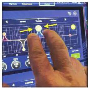
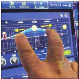
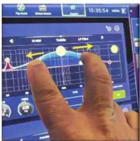
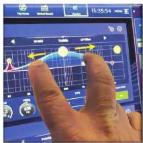
Pinch - Two fingers squeezed together, used to tighten or widen equalizer width (Q).
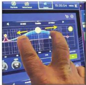
Swipe - Moving a page left to right or up and down by pressing, holding and moving in the required direction.
Press and Hold - Either a way to select all the paths on a current page for multiple editing or a way to engage a parameter function that may be critical if pressed in error, for example flattening the EQ is a press and hold function.
Widget - The name for a window or various windows displaying information on the GUI as part of a workflow.
Workflow - Visualizes the activities needed to mix audio.
Pot - A physical control used to adjust a level or value.
Chapter 2: HD96-24 Overview
Introducing the HD96-24 Digital Mixing System.
For decades Midas has been a driving force in the world of pro audio. Building on the incredible success of the X18 and PRO Series with their exemplary audio performance and road-proven rugged and reliable construction, the Midas PRO Series became the gold standard in concert touring and installed live sound. Offering the same outstanding sample-synchronised and phase coherent audio performance, interpolated control functions and intuitive navigation, the PRO2, PRO3, PRO6, PRO9 and later PRO-X Live Audio Systems have become one of the industry's main choices for live sound mixing.
Now the HDMI-24 pushes the boundaries further yet again with a 21" touchscreen for hands on instant access to all controls. Parameter adjustment becomes fast and easy with gesture touch interaction using the precise and accurate multi-touch display which allows up to 10 simultaneous touches. Featuring 144 Simultaneous field inputs and 123 (96 x Fixed Area = 24 x Matrix + 3 Output bases = 123) time-aligned, phase-coherent buzzes with no stealing of resources in channel or bus counts. True and consistent 95 kHz sampling frequency and 64 bit floating point processing provide exemplary quality audio processing, and the oversampled and interpolated digital signal processing algorithms, combined with the fully interpolated and touch sensitive user controls, result in the smooth continuous response and immediacy of working on an analogue console.
The HD96-24 features the rugged and road-proven Klark Teknik HyperMAC (HMAC) and SuperMAC (AES50-compliant) networking technologies with their ultra-low and deterministic latencies and robust error correction. Its powerful audio networking offers up to up to 624 inputs and 634 outputs at the 96kHz sample frequency depending on configuration.
HD96-24 Overview
The 24 VCA (Variable Control Association) and 24 POP (POPulation) groups, combined with the advanced touch screen navigation system, 26 leaders, assignable controls and innovative shortcut area allow simultaneous display and control of all the critical information required to craft an unprecedented mix experience.
Applications
The HD96-24 is the go-to-high-end Midas Digital Console System, akin to the 'Industry standard' Heritage 3000 and XLA. Although the HD96-24 is designed for the traditional touring live sound environment, it is also ideal for theaters, house of worship installations and broadcast. So, being a truly multi-functional console in the Midas tradition, the HD96-24 is suitable for many applications, such as
Live sound touring FOH or MOH duties.
Live sound theatre FOH or MOH duties.
Live sound house of worship FOH or MON duties.
System busses
The HD96-24 has comprehensive system busses to suit demanding applications, compromising of:
-
2 stereo solo busses, routable from all locations and allowing for dual operator.
-
3 master busses (1 Stereo 1 mono), routable from the miciline inputs (up to 144), and 96 aux busses.
-
24 matrix busses, routable from the micr-line inputs (up to 144), 96 aux busses and three stereo busses.
-
95 aux busses (either standard or flex-aux, routable from the micr-line inputs (up to 144) or flex) aux bus to aux bus for group or stem style processing.
All of the bus routings provide simultaneous and time aligned mixing of all the sources, which will be switchable for minimum latency requirements.
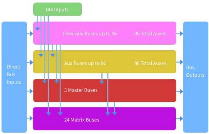
For monitor mixing, the master, matrix and aux busses can all be routed directly from the input channels, with independent level controls providing up to 123 monitor mix busses. Flexi-Aux busses allow group mixing of channels to be sent to Auxes, Matrices or the Masters, for example, mix and process all your drums via a Flexi Aux then send to an IEM Aux.
For traditional FOH sub group mixing, any (or all) of the aux busses can change to operate post-channel fader and pan (that is, aux gain fixed at unity).
Mix matrix
Fundamentally, the mix matrix defines the capability of the HDS6-24. Probably the best way to imagine the mix matrix is to think of an analogue console layout where inputs run vertically, and busses run horizontally. A mix matrix is usually defined as the number of busses and the quantity of simultaneously-mixable inputs there are per bus. The following diagrams illustrate the capability within the HDS6-24 system.
flowchart
graph TD
    A["Direct Bus Inputs"] --> B["24 Matrix Buses"]
    B --> C["3 Master Buses"]
    C --> D["Aux Buses up to 96"]
    D --> E["Aux Buses up to 96"]
    E --> F["Flexi-Aux Buses up to 96"]
    F --> G["144 Inputs"]
    G --> H["Bus Outputs"]
    H --> I["96 Total Auxes"]
    I --> J["96 Total Auxes"]
    J --> K["96 Total Auxes"]
    K --> L["96 Total Auxes"]
    L --> M["96 Total Auxes"]
    M --> N["96 Total Auxes"]
    N --> O["96 Total Auxes"]
    O --> P["96 Total Auxes"]
    P --> Q["96 Total Auxes"]
    Q --> R["96 Total Auxes"]
    R --> S["96 Total Auxes"]
    S --> T["96 Total Auxes"]
    T --> U["96 Total Auxes"]
    U --> V["96 Total Auxes"]
    V --> W["96 Total Auxes"]
    W --> X["96 Total Auxes"]
    X --> Y["96 Total Auxes"]
    Y --> Z["96 Total Auxes"]
    Z --> AA["96 Total Auxes"]
    AA --> AB["96 Total Auxes"]
    AB --> AC["96 Total Auxes"]
    AC --> AD["96 Total Auxes"]
    AD --> AE["96 Total Auxes"]
    AE --> AF["96 Total Auxes"]
    AF --> AG["96 Total Auxes"]
    AG --> AH["96 Total Auxes"]
    AH --> AI["96 Total Auxes"]
    AI --> AJ["96 Total Auxes"]
    AJ --> AK["96 Total Auxes"]
    AK --> AL["96 Total Auxes"]
    AL --> AM["96 Total Auxes"]
    AM --> AN["96 Total Auxes"]
    AN --> AO["96 Total Auxes"]
    AO --> AP["96 Total Auxes"]
    AP --> AQ["96 Total Auxes"]
    AQ --> AR["96 Total Auxes"]
    AR --> AS["96 Total Auxes"]
    AS --> AT["96 Total Auxes"]
    AT --> AU["96 Total Auxes"]
    AU --> AV["96 Total Auxes"]
    AV --> AW["96 Total Auxes"]
    AW --> AX["96 Total Auxes"]
    AX --> AY["96 Total Auxes"]
    AY --> AZ["96 Total Auxes"]
    AZ --> BA["96 Total Auxes"]
    BA --> BB["96 Total Auxes"]
    BB --> BC["96 Total Auxes"]
    BC --> BD["96 Total Auxes"]
    BD --> BE["96 Total Auxes"]
    BE --> BF["96 Total Auxes"]
    BF --> BG["96 Total Auxes"]
    BG --> BH["96 Total Auxes"]
    BH --> BI["96 Total Auxes"]
    BI --> BJ["96 Total Auxes"]
    BJ --> BK["96 Total Auxes"]
    BK --> BL["96 Total Auxes"]
    BL --> BM["96 Total Auxes"]
    BM --> BN["96 Total Auxes"]
    BN --> BO["96 Total Auxes"]
    BO --> BP["96 Total Auxes"]
    BP --> BQ["96 Total Auxes"]
    BQ --> BR["96 Total Auxes"]
    BR --> BS["96 Total Auxes"]
    BS --> BT["96 Total Auxes"]
    BT --> BU["96 Total Auxes"]
    BU --> BV["96 Total Auxes"]
    BV --> BW["96 Total Auxes"]
    BW --> BX["96 Total Auxes"]
    BX --> BY["96 Total Auxes"]
    BY --> BZ["96 Total Auxes"]
    BZ --> CA["96 Total Auxes"]
    CA --> CB["96 Total Auxes"]
    CB --> CC["96 Total Auxes"]
    CC --> CD["96 Total Auxes"]
    CD --> CE["96 Total Auxes"]
    CE --> CF["96 Total Auxes"]
    CF --> CG["96 Total Auxes"]
    CG --> CH["96 Total Auxes"]
    CH --> CI["96 Total Auxes"]
    CI --> CJ["96 Total Auxes"]
    CJ --> CK["96 Total Auxes"]
    CK --> CL["96 Total Auxes"]
    CL --> CM["96 Total Auxes"]
    CM --> CN["96 Total Auxes"]
    CN --> CO["96 Total Auxes"]
    CO --> CP["96 Total Auxes"]
    CP --> CQ["96 Total Auxes"]
    CQ --> CR["96 Total Auxes"]
    CR --> CS["96 Total Auxes"]
    CS --> CT["96 Total Auxes"]
    CT --> CU["96 Total Auxes"]
    CU --> CV["96 Total Auxes"]
    CV --> CW["96 Total Auxes"]
    CW --> CX["96 Total Auxes"]
    CX --> CY["96 Total Auxes"]
    CY --> CZ["96 Total Auxes"]
Network
The network of the HD96-24 utilises the physical connectivity of Ethernet (EtherCon® connectors and Cat SE/copper cable) but replaces its data protocol with AES50 protocol (implemented as SuperMAC) and the HyperMAC high-capacity system, which are more suited to high quality, low latency audio distribution. The use of the AES standard allows straightforward interfacing with any third-party hardware that also utilises this connection.
AES50 connections carry digital audio and control data bi-directionally down a single cable. Cut 5c cable is used for the 'local' connections and the dual digital 'snake' equivalent to a 384-channel analogue multi-core, 192 channels per snake connection between console and YO. The combination of audio, control, clock and third-party Ethernet data in a single network means that the hardware interfaces on a single B.45 connection.
All system connections can be duplicated for full dual redundancy.
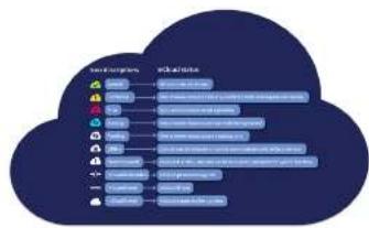
mCloud Network
The Midas mCloud network is a brand-new concept in file and system management. The HD96-24 has built in Wi-Fi capabilities which allow the surface to share its information over a Wi-Fi connection and any other network connections to the mCloud. Be reassured the connection is completely safe and great lengths have been taken to keep information secure.
The mCloud can be used to store your show files, preset files and all other types of data from the console. If you leave your USB stick with your vital settings at home, you can directly log into your mCloud account and load your show file straight to the HD96.24 without breaking a sweat.
New system updates can be downloaded directly to the surface ready for you to update when you're ready. A list of all previous software versions will be stored on the HD96-24 for peace of mind.
It also allows audio rental companies to keep a track of registrations, software versions, warranties and diagnostic logs. All the admin for running a busy hire company in one place.
Each user of the HD96-24 will be prompted to set up a user profile which also in turn configures your mCloud account. Visit cloud.midasunsoles.com to set up and use your account.
HD96-24 software
The operating system of the HD96-74 is Linux, which is an open-source, stable, proven operating system (OS). Linux is used in many mission-critical applications worldwide and has allowed Midas' software engineers to write a ground-up system that contains no 'hidden' or unused code. This has resulted in an efficient compact application, which is quick in operation, quick handling and comparatively easy to debug.
Graphic User Interface (GUI)
The HD96-24 has a 21" touch screen that provides a quick and intuitive workflow. Modern touch gestures such as pinch and smooth touch screen faders have been included to speed up work flow and let you concentrate on the mix. Not only does the GUI reflect what is happening on the control surface, but it also provides extra functionality via a top and side bar menu. These menus provide access to all the pages that you will require to set up, configure, manage and operate the entire control surface.
Gone are the days of only one touch on a screen at a time. Use both hands to manipulate up to 10 faders at a time if you so wish.
Pinch gesture showing EQ width adjustment.
Independent widget style areas are extensively used to display various different types of information at once, all fully customisable to suit your workflow.
System card expansion
The H095-24 has 2 x CM-1 slots built in for further audio expansion. Adding up to an additional 128 channels of I/O greatly increases networked capabilities. Virtual sound checks and recording have never been easier to set up and achieve with flexible options. Being able to support new and emerging protocols via its two industry-standard expansion slots gives the H095-24 a greatly extended shelf life.
HD96-24 Basic Operation
Chapter 3: Before You Start
Principles of operation
Control surface operation is based on the concept of colours and groups rather than 'layering' or 'paging', which is the case with most digital consides on the market today. With so many channels available it is far easier to remember them by their user-configured individual/group colour and name rather than their channel number. Tags can also be used to group channels together in order to speed up certain functions, for example, changing the colour of all the drum channels.
The control surface is populated with instantly recognisable controls that are logically distributed in major sections, so that all the controls you need to access most of the time are always on the control surface, while the remainder are only one action away. You can display all 120 meters, both on the control surface and the Gill via the Console View workflow, to give instant monitoring and metering feedback.
Operating modes
You can change certain aspects of the control centre operation by assigning different tasks to certain areas of the control surface.
Hints and tips
Checking the Console View screen frequently is a good idea. This provides at a glance an overview of the control surface's input/output status.
The Manchine (Multi Edit) page is a great place to set various inputs or outputs to user defined levels or settings e.g. for setting all faders to dB, setting all contributions into a particular aux to be Pre-fade, or routing a large number of paths to the Stereo bus. Details of how it works can be found in full HD96-24 manual.
User Journey
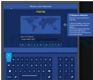
When the HDS6-24 is switched on for the first time you will be presented with the welcome screen, then the Country or Region selection page. In order to enjoy the full benefits of the mCloud system it is advised an internet wired or wireless network connection is available. You will then be guided through the various pages to set up and login into your mCloud account.
Setting up a User Profile
The HD96-24 incorporates a system of User Profiles for storing information about the console set-up and other User Info. Each person using the HD system can have their own profile which keeps all your show files and other useful information on the console and via the mCloud network if the HD system has an active internet connection.
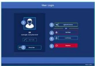
After the system has been registered and is turned on for the second time you will be asked to either log in or create and add a new profile.
-
Current selected profile.
-
Change user profile
-
Login to your mCloud account (all active files in your account will be available in Show Manager).
-
Safe Mode (the show database is not available in safe mode, but you can still mix).
-
Activates the lock screen.
-
Shutdown the console.
Saving your work
We recommend that you save your work regularly to the mCloud and a USB stick while carrying out the procedures included in this guide. Not only is this good practice during normal operation, but in this instance, it may save you from losing some set-ups that could prove useful later on.
Saving a show versus storing a scene
It is important to understand the differences between saving a show and storing a scene. Storing a scene saves the current settings of the system to the show file. Scene data is never updated unless you manually store a scene. The show file remains unsaved in RAM. Although the state of the control surface is copied every five seconds, it is not stored in a scene. Instead, it is placed in the WRAM (non-volatile random-access memory) of the control surface's memory, which is a type of RAM that doesn't lose its data when the power goes off. If the control surface loses power accidentally, these settings are loaded so that audio parameters are identical, thus avoiding audio level jumps.
Saving a show copies the show file onto the Internal solid-state disk of the control surface. This provides you with a 'permanent' copy, provided you shut down the system properly as detailed in the following section. You also have the option of saving your show to your Midas mCloud account. This gives extra security to your work and allows your show file to be restored to a console even if you have lost your USB stick.
Shutting down the control centre properly
When switching off the control surface, we recommend that you use the shutdown option in the GUI menu.

Hold Shutdown for a short time while the line traces around the outside of the button. The surface will then start the shutdown routine, the screens will go blank, the Macas logo will briefly be displayed, then the screen will go blank for a second time indicating the shutdown procedure has finished. Only once the system has been shutdown correctly is it safe to turn off the power switch. By using shutdown, the cached copy of the sheet data, which is maintained by the system, is automatically stored. Shutdown then uses the current show file, WIAM data and cache files to restore the control surface to exactly the same state as at power down; even to the point of loading the unsaved show and placing you at the correct scene, with non-stored scene data at the control surface.
If you don't use the Shutdown option the audio parameters are still restored, but the show and show status (saved/unsaved) cannot be restored automatically. You must manually reload the show, and any unsaved changes will be lost.
The Midas mCloud system
mCloud handles all show file storage at its basic level. Imagine leaving your USB stick at home but not worrying as once you sign into your mCloud account on the surface you can see all your shows in one convenient place.
Below is a status list to show how your files are synced or not.
Status if connected to the mCloud:
- Synced All versions of this show have been pushed to the mCloud; any newer mCloud versions have been spaced to the console.
• Pending One or more newer versions have been created on the console and will be synced shortly.
- Syncing Edits are being pushed to and/or pulled from the mCloud.
• Conflicted Edits have been made on both console and cloud awaiting user to select the correct current version.
- Error The sync service encountered a problem trying to sync this resource (e.g. due to an issue communication with the mCloud).
"Connected to mCloud" means the console can reach the mCloud server, the current user is mCloud-enabled and a valid password has been entered (or a valid token saved from a previous session).
Status if offline:
Synced Latest version of shows on the console have been synced to the mCloud. Newer mCloud versions will be unknown.
• Pending One or more newer versions have been created on the console and will be scheduled for sync next time the console is connected.
Syncing n/a
• Conflicted n/a
Error n/a
flowchart
graph TD
    A["Cloud Service Providers"] --> B["Google Cloud"]
    A --> C["Amazon Prime"]
    A --> D["Amazon Prime & Amazon Services"]
    A --> E["Google Cloud"]
    A --> F["Amazon Prime & Amazon Services"]
    A --> G["Amazon Prime & Amazon Services"]
    A --> H["Google Cloud"]
    A --> I["Amazon Prime & Amazon Services"]
    A --> J["Amazon Prime & Amazon Services"]
    A --> K["Google Cloud"]
    A --> L["Amazon Prime & Amazon Services"]
    A --> M["Amazon Prime & Amazon Services"]
HD96-24 Basic Operation
Chapter 4: About the Control Surface
The HD96-24 has been designed from the ground up to give the operator easy-to-use touchscreen controls along with familiar analogue style controls. This clever combining of working methods ensures any engineer can walk up to this console and instantly feel at home, but when required can delve deeper into the system to achieve complex routing and detailed sonic manipulation.
The surface is controlled on a robust Midsat steel frame chains to those to be established. Vidas analogue products. All of the surface is controlled from two processors. All associated power supplies, computer motherboards, VH-R router, Bluetooth, memory, graphics cards etc. are housed within the surface, which also contains a digital audio meter box that supports local 1/2 connectors on the rear panel. Substantial forced air-cooling is provided by a bulkhead and large (but slow moving) internal fans. The large capacitive touchscreen displays a large quantity of information and can be customised to match your workflow to make mixing a pleasure. Using modern day gestures from mobile phone and tablet technology such as pinch and swipe makes parameter manipulation even faster and more responsive with up to 10 simultaneous touch screens.
The HD96-24 system is designed to be easy to see for colour blind people. Great care has been taken to make the system visible to as many types of colour blind people as possible.
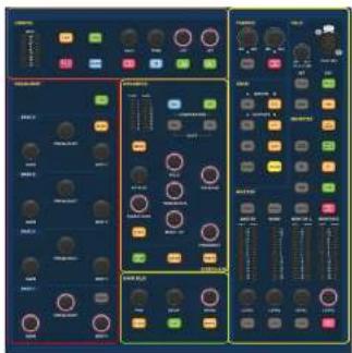
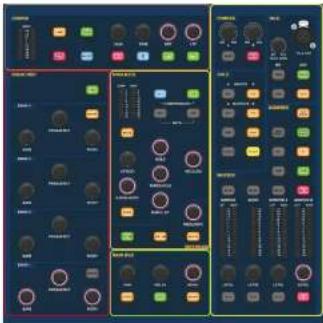
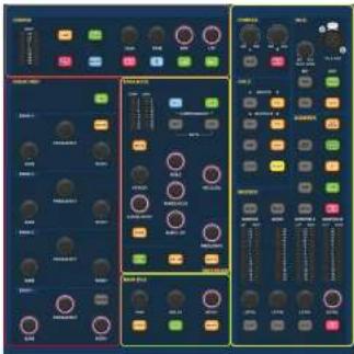
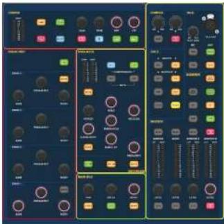
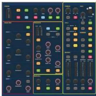
Control surface layout
The HD96-24 surface can be spilt in to 7 distinct areas making operation quick and precise with all controls close to hand. The areas are defined in the diagram below:
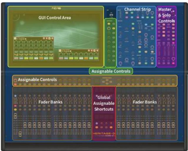
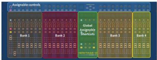
The HD36-24 has 4 fully assignable fader banks split into three banks of eight faders and one bank with four faders each with individual full colour ultra-bright LCD displays. Any section can be assigned to any function, be it inputs, outputs, POPs, VCA, Matrices or Masters. This concept allows the user to fully customise the surface to suit their mixing preferences.
The global assignable shortcuts area can be used to provide many simple and complex functions with macro style controls right at your fingertips. E.g. Pop group selection, triggering macros or automation recall.
The assignable controls above the faders and to the side of the GIII can be fully customised to suit your workflow. Functions can be changed quickly with the cursor arrow controls. For e.g. altering pan position, and control or gain changes.
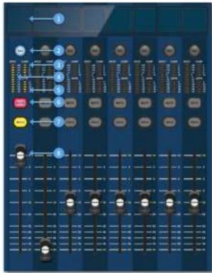
Channel strip layout
Each channel strip within a bank provides:
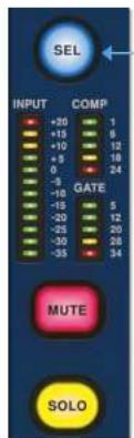
[1] LCD Display - A high-resolution display providing metering, channel information and flip status, and local parameter values.
Sel (Fader Channel Select) - This button selects the channel for a variety of operations, including adjusting parameters from the GUI and assigning to the channel detail area.
[1] COMP - Compressor gain reduction meter (GR).
INPUT - Input metering.
GATE - Gate gain attenuation meter (GA).
[6] MUTE - Press the MUTE button to mute (turn off) the channel.
☐ SOLO - Press SOLO to listen to the channel signal
LEVEL - The fader is touch sensitive providing gain control from to +10dB (or +6dB if contributing to an output bus).
HD96-24 Basic Operation
Global Assignable Shortcuts
The Global Assignable Shortouts area in the centre of the surface allows various functions to be placed within easy reach of the user. Twelve full colour LCD displays with selection buttons show a great deal of information and allow for complex operations to be recalled with one button press.
Home
The HOME key is located under the Shortcuts area. When pressed the HOME workflow is brought to the GUI.
Tap
The TAP button is used to set the tempo for effects assigned to the Global TAP tempo function. Commonly 8 taps are required for an accurate tempo,
Arrow Keys
These two keys tab through the various pages of the global assignable shortcuts pages which can be fully customised.

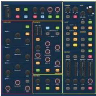
The familiar looking Channel Detail Area is used for hands on control with sections for Config, Equaliser, Dynamics, Phones, Talk, Solo, Monitor, Main Bus and Master. This area makes using the surface easy to use with a familiar analogue feel. The 4 x Change Over (C/O) buttons for Master, Mono, Monitor A and Monitor B assign the control to the fader below for quick control by fader level.
Front and rear panel connections
The surface has connector panels on both the front and rear. The front connector panel to the right of the GUI has an XLB socket and a USB socket for connecting a talk mic and USB device, respectively. For example, you can connect a USB memory stick for show file backup and transfer. Under the armrests at either side there are two 6.35 mm headphone sockets which link to Mon A and Mon B respectively.
Chapter 5: System Setup
Unpacking the equipment
After carefully unpacking the equipment, save all packing materials, as they will prove useful should it become necessary to transport the equipment later. Inspect the equipment carefully for any sign of damage incurred during transportation. It has undergone stringent quality control inspection and tests prior to packing and was in perfect condition when it left the factory. However, if the equipment shows any signs of damage, notify the transportation company without delay. Only you, the consignee, may institute a claim against the carrier for damage during transportation.
Racking the I/O
Please take note of the rack requirements as detailed below:
To ensure the correct installation and function of the outboard equipment, any rack has to meet the following general requirements:
Shock mounting (for non-installation environments)
The rack must provide adequate shock protection of the units it houses by incorporating appropriately designed shock protection methods. For example, a foam-suspended rack or a frame suspended on anti-vibration mounts.
Ventilation
The HD96-24 has air intake vents on each side of the console. Air is drawn in through the console side vents and exits via the two fans on the rear of the surface. It is vital none of these airways are blocked as overheating may occur if airflow is restricted.
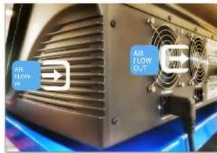
The Midas I/O units have been designed such that their internal ventilation airflow is drawn in through the front of the unit and expelled through the rear. To facilitate this, rack design must ensure that cool air can flow freely through the rack in the same direction, that is, in through the front of the rack and out through the rear. Situations where the air flows in a circular direction around and through a Midas I/O unit must be prevented. Midas recommends that racks with fully opening front and rear doors are used.
Caution
Never combine units in the same rack that have been designed for a ventilation air flow direction other than that designed for the MIDAS units. To avoid this, we recommend that any non-MIDAS units are housed separately.
Rack mount supports
Always secure the rear of the Midas I/O units to the rack via their rear rack mount support brackets. These brackets are fitted to every Midas I/O unit and are recommended for use in touring applications.
Handles on rack case
You must ensure that there are sufficient external handles fitted to the rack casing to enable the rack to be manoeuvred easily and safely, and by the number of personnel suitable for the task. Also, these handles must be fit for purpose.
Clearance at rear of units
Ensure an adequate clearance at the rear of the units to provide sufficient free space to enable the cables to achieve their minimum bend radius.
Securing the cables
We recommend that the cables at the rear of the units be tidied using lacing bars and cable ties. This should provide optimum access to the rear of the units for connecting other cables, switching the units on/off etc., and also to give maximum visibility of the units' LEDs for determining communication status, link status, condition of audio etc.
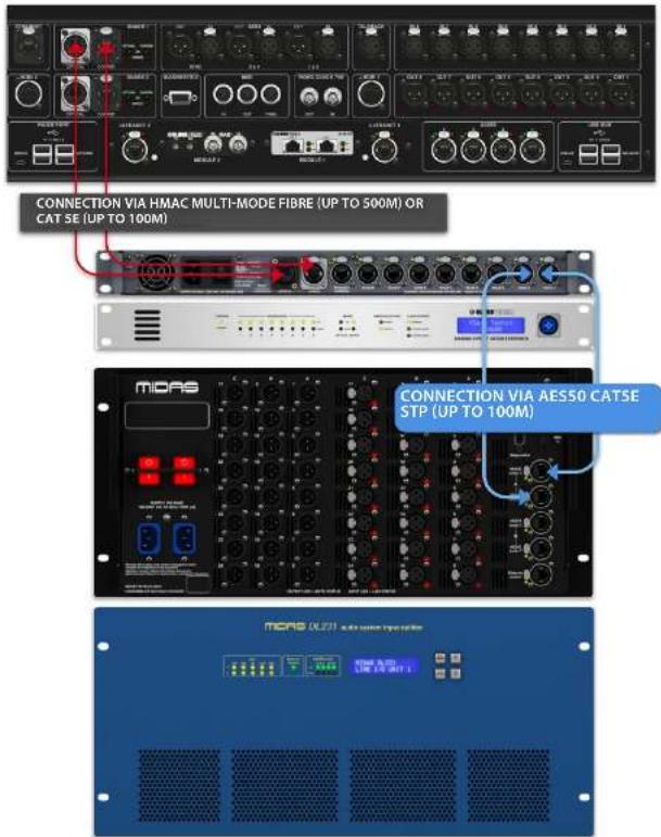
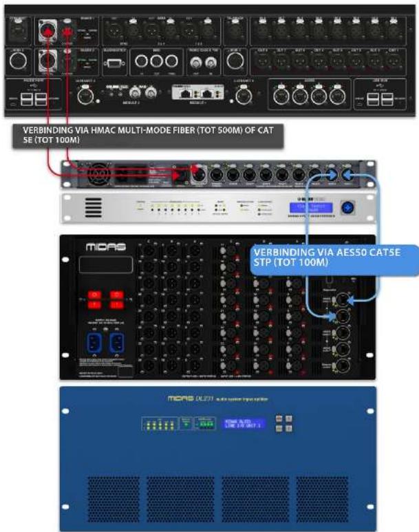
Connection instructions
There are currently two ways to connect the system equipment together.
-
HD96-24 surface to a Klark Teknik DN9680 via copper (up to 100 m) or with a multi-mode (MM) fibre optic snake (up to 500 m). Then Klark Teknik DN9680 to I/O box (for example, DL231) via CatSE (up to 100 m).
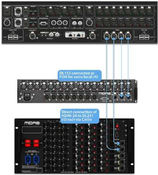
-
HD96-24 surface direct to I/O (for example, DL231) via CatSE (up to 100 m).
It is imperative only STP Cat5E Rated cables are used!
Length = 100M Point to point as per the Cate5E ethernet protocol - Please take into consideration any in line connections or links reduce the overall cable length.
AESSO CatSe STP vs UTP cables.
Music Tribe are standardising the use of Ethercon cables used for AES50 connections and state that customers must use Shielded Twisted Pair (STP) cable only with shielded R45 plugs and Ethercon shells.
STP cable has the added advantage of a foil or braided shield that guards the cable against electromagnetic interference. A good foil or braided shield and correctly connected shielded plugs and shells also helps protect against Electrostatic discharge (ESD) that can be the cause of dropouts on AES50 connections.
Occasionally shielded Ethercon cables will leave the shield disconnected on one end to help with ground loops, even though it has no benefit for AES50 connections. These connections should have continuity of the shield on both ends including the Ethercon shells. This will ensure the best possible protection against strong ESD impacts, such as handling discharges or even lightning strikes in the neighbourhood.
All AES/EBU connections must use good quality 110Ω AES/EBU cable to ensure correct operation.
HD96-24 Basic Operation
System components
Below is a list of currently compatible system I/O components with the
HD software. When I/O is connected to the HD96-24 system it will be necessary to be update to the latest HD I/O software. The updater is built into the console and guides you through the update process. Once updated, I/O boxes will still be compatible with Pro Series consoles.
Note: I/O boxes will need to be updated in order to work with the HD96-24 system. The I/O Box and Device updater can be found in the Update Manager page. With all your I/O connected press Sync I/O and follow the instructions. Updated I/O boxes are fully compatible with Pro Series consoles.
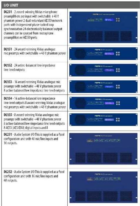
I/O UNIT
DL231 - 2 award-winning Midas microphone preamplifiers per input with switchable 148 V phantom power 2 dual redundant AES50 network ports with independent phase-locked loop synchronisation 24 electronically balanced output channels can be sourced from microphone preamplifiers or AES50 ports
DL151 - 24 award-winning Midas analogous mic preamps with switchable +48 V phantom power
DL152 - 24 active-balanced low impedance line-level outputs
DL153 - 16 award-winning Midas analogue mic preamps with switchable +48 V phantom power 8 active balanced low impedance line level outputs
DL154 - 16 active-balanced low impedance line-level outputs 8 award-winning Midas analogue mic preamps with switchable +48 V phantom power
DL155 - 8 award-winning Midas analogue mic preamps with switchable +48 V phantom power 8 active-balanced low-impedance line level outputs 8 AES3 (AES/EBU) digital inputs and 8
DL251 - Audio System I/O This is supplied as a fixed configuration unit with 48 microline inputs and 16 outputs.
DL252 - Audio System I/O This is supplied as a fixed configuration unit with 16 micr-line inputs and 48 outputs.
Connection Via DN9680
HD96-24 Basic Operation
Direct connection of I/O
To power up the system
Important Note
Make sure your speaker system, In-ears or monitor wedges are muted until the start-up of the system has been completed.

After all system interconnections have been made, start up the system by doing the following:
Switching on the HD96-24
-
Plug the two mains cables into the mains power outlets. Both power supply modules should be supplying power to the HD95-24 surface for correct redundant operation.
-
Plug the connectors of the mains cables into the IEC mains sockets on the rear of the HD96-2
-
Tum on the power to the HD96-24 surface by switching both AC POWER switches on. The surface will boot up. Once the default GUI screen is displayed, it is ready for use.
To switch off the HD96-24 surface
-
Make sure you have saved any shows, scenes or settings you require.
-
In the GUI, select Menu from the top bar, then press and hold the red
SHUTDOWN button at the bottom of the menu until the line traces around the outside of the red button. The shutdown procedure will then initiate.
- The screen will go blank, the Midas logo will briefly be displayed, then the screen will go blank for a second time indicating the shutdown procedure has finished. Only once the system has been shutdown correctly is it safe to turn off both AC power switches (near of surface).
HD96-24 Basic Operation
Setting up the ID of the unit(s)
After connecting up your system, you may need to set up the ID of the unit(s) in the rack, such as the DL231 I/O or DL15s (IO), as each unit within the same family of units must have its own unique ID number.
Please refer to the DL series or HD manuals for full details on changing unit ID's.
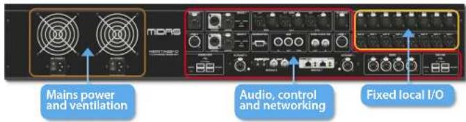
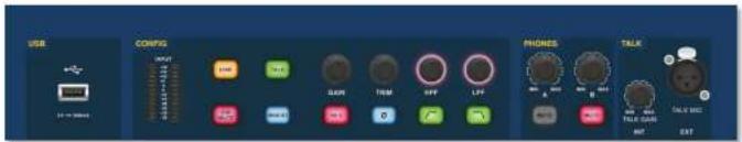
A connector panel on the rear of the control surface has two main sections. On the left are two mains power inlet and ventilation assemblies, with 2 x AC power switches below. The right section contains connections for the Snake/Multicore, Ethernet control, eight analogue audio inputs and outputs, three AES3 inputs and outputs, diagnostics, word clock, Twin HDMI™ external monitor outputs, Midi, Talkback line level input, two expansion card slots and USB Hub.
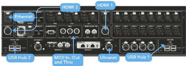
External interfaces and peripheral devices
Various devices can be used with the HD%-24 such an external USB keyboard.
MIDI Standard S-pin connectors are housed in the rear panel for use as MIDI IN, OUT and THRU ports. These are also fitted on some I/O units (DL231, DL251 for example) and, therefore, are available at both the FDR and the stage locations.
USB 2 x 4 away USB 3.0 hubs are provided on the rear of the HD96-24. In addition, a USB port can be found to the right of GUI screen for convenient file transfer. The Faster Port USB outputs are only for use with future faster bank expansions.
External monitor The HD96-24 has 2 HDMI ^™ connections on the rear panel to connect extra displays (1920 x 1060p 59.94Hz/60Hz 16:9 & 720 x 480p 59.94Hz/60Hz 16:9 supported).
Ethernet port The Ethernet port on the rear of the surface is for connecting the H095-24 to a network or external wireless router.
Ultranet 2 x Ports for connecting Ultranet enabled devices.
Chapter 6 Surface Controls
The HD96-24 has full multi-touch screen control. This gives the user some of the feeling of working with analogue consoles again whilst at the same time incorporating modern ways of interacting with everyday products like smartphones and tablets. One of the advantages digital consoles have over analogue ones is that their channel count is not limited by the control surface hardware. However, this means that only a certain number of channels can be shown on the control surface at any time, while the others are available at the touch of the screen (GUI) or assignable shortcuts area.
Pressing the SEL (select) button on any input or output will bring the chosen channel to the surface controls (also to the touch screen wroget). From here adjustments to many common parameters can be changed such as Gain, EQ, Dynamics or Pan position. This way of working has a familiar feel that you will understand and be comfortable to use. Mute will turn the channel off and solo will send the audio of the selected path to either the A or B solo bus depending on path settings.
Navigating via the surface detail area
The surface is laid out with a familiar analogue feel for easy operation. Everyday functions are available for hands on operation. All functions are mirrored in the Gill with parameter values highlighted on touch. This allows you to make changes quickly to the selected channel or path.
HD96-24 Basic Operation
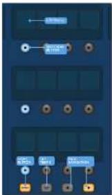
Config
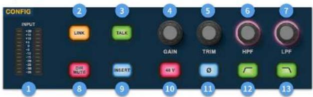
☐ Meters - 12 LEDs Stereo input meters display signals from -35 dB to 20 dB.
Link - Links the currently selected input channel to the next input. Note outputs always link odd to even, i.e. Aux 1 to 2 etc.
3 Talk - Send the talk bus to the select channel.
Gain - Adjust the gain of the input channel pre-amp.
5 Trim - Adjust the trim level for inputs -40 to 20 dB or for Aux, Matrices and Master Busses -12 to 6 dB.
HPF - High Pass Filter (HPF) control with a range from 10 Hz to 10 kHz.
LPF - Low Pass Filter (LPF) control with a range from 40 Hz to 20 kHz.
Dir Mute - Mutes the direct out of the currently selected channel.
Insert - Switches on the insert point on the selected channel.
13 48 V - Activates 48 V phantom power on the selected input channel.
☐ - Polarity Switch. Changes the polarity of the selected channel by 180° (often inaccurately called phase reverse as the button only inverts polarity).
LDC HPF on - Activates the HPF.
LPF on - Activates the LPF.
Equaliser
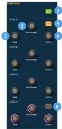
① On - Turns the Equaliser on for the selected channel.
Gain - Each band has + 16.2 dB of range.
① Frequency - Each band as a frequency range of 16 Hz to 25 kHz.
4 Width - The width or 0 of an EQ band can be changed from 0.3 to 5.3.
Shape - Changes the shape of Band For inputs the shape options include, Bell, Bright, Classic and Soft. For outputs the Shape button has Shelf, IP 6 dB, IP 12 dB and Bell modes.
Shape - Changes the shape of Band For inputs the shape options include, Bell, Deep, Classic and Warm. For outputs the Shape button has Shelf, HP 6 dB, HP 12 dB and Bell modes.
Dynamics
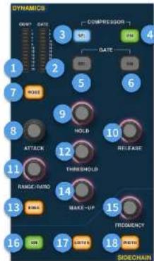
Compressor GR Meter - Compressor (Comp) Gain Reduction Meter (Range - 1 dB to - 23 dB).
GATE GA Meter - Gate Gain Attenuator Meter Range (-1 dB to -34 dB).
① SEL Comp - Selects the compressor setting for the selected channel.
④ ON - Turns the compressor on for the selected channel.
SEL Gate - Selects the gate setting for the selected channel.
ON - Tums the gate on for the selected channel.
[7] Mode - Selects the mode of the compressor (Corrective, Adaptive, Creative and Vintage) or gate (Gate or Ducker).
2 Attack - Controls the attack settings of the gate or comp.
Hold - Controls the hold value of the gate. Hold is the amount of time the gate is open until the release part of the gate starts.
Release - Controls the release characteristic of the gate and comp.
3 Range/Ratio - Range relates to the gate and controls the amount of signal allowed to pass when the gate is closed. This is useful on drums to allow some of the dry drum sound through when the gate is closed. Ratio relates to the comp. With a ratio setting of 3:1 for every 1 dB above the threshold point the signal will be turned down or compressed by 3 dB.
(3) Threshold - Adjust the point at which either the gate opens, or compression starts to take place.
3 Knee - Changes the compression knee setting [Hard, Medium or Soft].
Make-Up - Adds gain to the compressors output. This allows you to balance the levels of the compressor when on and off by increasing the make-up gain to match the amount of gain reduction taking place. (Range 0 dB to 24 dB).
[15] Sidechain Frequency - Set the frequency that the sidechain of the gate or comp listen to in order to give tighter control of a certain range of frequencies.
On - Turns the sidechain of the gate or comp on/off.
[1] Listen - Sends the selected sidechain frequency to the solo bus for monitoring and to give accurate adjustment of the frequency.
Width - Changes the width of the sidechain for the gate and comp (0.1 Oct, 0.3 Oct, 1 Oct and 2 Oct).
Phones
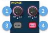
(1) Phones A - Level control.
② Phones B - Level Control.
4 Phones 0 - Nute button.
[4] Phones B - Mute button.
Talk
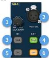
☐ Talk Gain - Adjust the gain of the surface Talk MIC input.
[3] Talk Mic - XLR input for local talk mic.
3 Talk INT (Internal) - Allows the talk mix to be sent to the internal talk bus. For example, it can be used to send your talk mix into a channel to test signal flow.
Talk EXT (External) - Allows your local talk mic to be routed to the Ext Talk.
OSCINT - Activates the oscillator on the selected internal bus.
OSC EXT - Sends the oscillator to the Ext Talk bus. This can be used to send the oscillator to a channel if required by patching the Ext Talk out in the monitor patching page to a channel.
HD96-24 Basic Operation
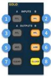
Solo
flowchart
graph TD
    A["INPUT"] --> B["FL"]
    C["OUTPUT"] --> D["FL"]
    E["CONT"] --> F["ADD"]
    G["CLEAR"] --> H["CLEAR"]
    style A fill:#00FF00,stroke:#333
    style C fill:#FFD700,stroke:#333
    style E fill:#FF6347,stroke:#333
    style G fill:#FFFF00,stroke:#333
    style B fill:#FFA000,stroke:#333
    style D fill:#FFA000,stroke:#333
    style F fill:#FFA000,stroke:#333
    style H fill:#FFFF00,stroke:#333
A PFL - Indicates an input channel is being heard by Pre Fader Listen via Solo A bus.
B PFL - indicates an input channel is being heard by Pre Fader Listen via Solo B bus.
A PFL - Indicates an output channel is being heard by Pre Fader Listen via Solo A bus.
B PFL - Indicates an output channel is being heard by Pre Fader Listen via Solo B bus.
5 Add (A) - Allows more than one input channel to be listened at once on the A solo bus.
5 Add (B) - Allows more than one input channel to be listened at once on the B solo bus.
(1) Clear (A) - Clears any current solo selections.
☐ Clear (B) - Clears any current solo selections.
Main Bus
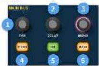
(1) Pan-Controls the position of the signal in the stereo field.
[2] Delay - adjusts the delay time for the selected channel.
Mono - Adjusts the send to the Mono Bus.
[4] Stereo - Sends the selected channel to the Stereo Bus.
[5] On - Turns the selected channel's delay time on.
Mono - Sends the selected channel to the Mono Bus.
Monitor
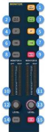
(1) Out Swap - Completely swaps the A and B Monitor Busses over meaning A becomes B and vice versa. For example, this allows you to hear a wedge monitor mix on the in-car monitor bus if desired without having to re-patch.
2) Talk Back - Allows the rear line level talkback input to be directly inputted into the Monitor A bus.
④ Talk Back - Allows the rear line level talkback input to be directly inputted into the Monitor B bus.
ST-Routes the stereo bus to the monitor A bus.
ST-Routes the stereo bus to the monitor B bus.
(€) DIM A - Turns the level of the Monitor A bus down by 6 dB.
DIM B - Tums the level of the Monitor B bus down by 6 dB.
5 Mute - Mutes the Monitor A bus.
Mute - Mutes the Monitor B bus.
Monitor A Metering - Stereo 20 LED meters, -36 dB to 21 dB.
Monitor B Metering - Stereo 20 LED meters, -36 dB to 21 dB.
12 Monitor A Level - Level control. Maximum level 10 dB
11 Monitor B Level - Level control. Maximum level 10 dB.
(14) C/O - Sends the monitor A level control to the faster directly below for easy adjustment.
☐ Q/Q - Sends the monitor B level control to the fader directly below for easy adjustment.
Master
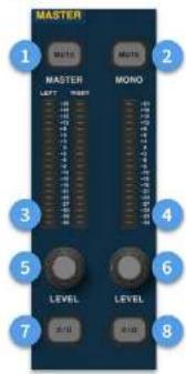
① Master Mute - Mutes the Master Stereo Bus.
Mono Mute - Mutes the Mono Bus.
① Master Meters - Stereo 20 LED meters, 36 dB to 21 dB.
4 Mono Meter - Stereo 20 LED meters, -36 dB to 21 dB.
Master Stereo Bus Level - Level control, Maximum level 10 dB.
Mono Bus Level - Level control. Maximum level 10 dB.
C/O - Sends the Master Stereo Bus level control to the fader directly below for easy adjustment.
C/O - Sends the Mono Bus level control to the faster directly below for easy adjustment.
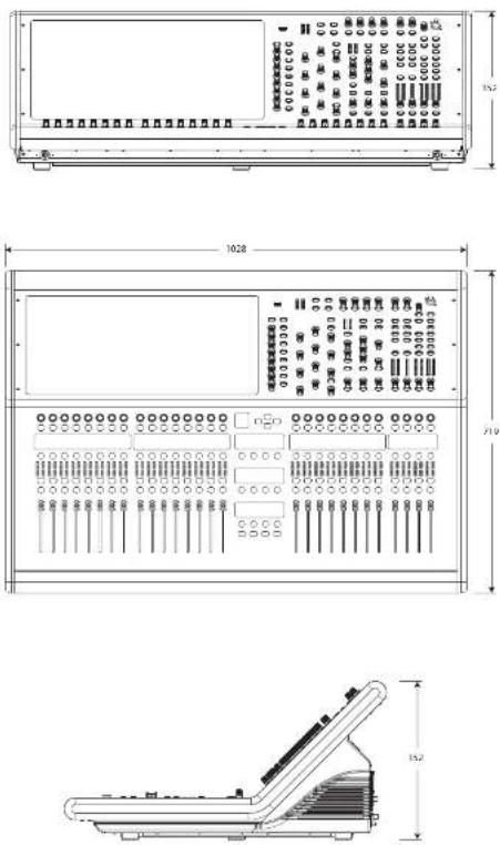
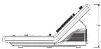
HD96-24 Dimensions
HERITAGE-D
HD96-24

natural_image
Technical diagram of a rectangular electronic device with internal components and mounting holes (no text or symbols)

natural_image
Technical line drawing of a mechanical component with dimension annotations (no readable text or symbols)HERITAGE-D
HD96-24
Service et assistance
Fiabilite (reduendance)
Logiciel HD96-24
GUI
Service et assistance

flowchart
graph TD
    A["Cloud Service"] --> B["Cloud Services"]
    B --> C["Cloud Management"]
    C --> D["Cloud Security"]
    D --> E["Cloud Security Services"]
    E --> F["Cloud Security Management"]
    F --> G["Cloud Security Services"]
    G --> H["Cloud Security Management"]
    H --> I["Cloud Security Services"]
    I --> J["Cloud Security Management"]
    J --> K["Cloud Security Services"]
    K --> L["Cloud Security Management"]
    L --> M["Cloud Security Services"]
    M --> N["Cloud Security Management"]
    N --> O["Cloud Security Services"]
    O --> P["Cloud Security Management"]
    P --> Q["Cloud Security Services"]
    Q --> R["Cloud Security Management"]
    R --> S["Cloud Security Services"]
    S --> T["Cloud Security Management"]
    T --> U["Cloud Security Services"]
    U --> V["Cloud Security Management"]
    V --> W["Cloud Security Services"]
    W --> X["Cloud Security Management"]
    X --> Y["Cloud Security Services"]
    Y --> Z["Cloud Security Management"]
    Z --> AA["Cloud Security Services"]
    AA --> AB["Cloud Security Management"]
    AB --> AC["Cloud Security Services"]
    AC --> AD["Cloud Security Management"]
    AD --> AE["Cloud Security Services"]
    AE --> AF["Cloud Security Management"]
    AF --> AG["Cloud Security Services"]
    AG --> AH["Cloud Security Management"]
    AH --> AI["Cloud Security Services"]
    AI --> AJ["Cloud Security Management"]
    AJ --> AK["Cloud Security Services"]
    AK --> AL["Cloud Security Management"]
    AL --> AM["Cloud Security Services"]
    AM --> AN["Cloud Security Management"]
    AN --> AO["Cloud Security Services"]
    AO --> AP["Cloud Security Management"]
    AP --> AQ["Cloud Security Services"]
    AQ --> AR["Cloud Security Management"]
    AR --> AS["Cloud Security Services"]
    AS --> AT["Cloud Security Management"]
    AT --> AU["Cloud Security Services"]
    AU --> AV["Cloud Security Management"]
    AV --> AW["Cloud Security Services"]
    AW --> AX["Cloud Security Management"]
    AX --> AY["Cloud Security Services"]

natural_image
Close-up of a metallic industrial fan with cooling fins and ventilation units (no visible text or symbols)natural_image
Technical line drawing of a rectangular electronic device with multiple ports and connectors (no text or symbols)

natural_image
Technical line drawing of a mechanical component with dimension annotations (no readable text or symbols)HERITAGE-D
HD96-24
HD96-24 Host-Softwareversion
Hold Shutdown for a short time while the line traces around the outside of the button. The surface will then start the shutdown routine, the screen will go blank, the Atlas logo will briefly be displayed, then the screen will go blank for a second time indicating the shutdown procedure has finished. Only once the system has been shutdown correctly is it safe to turn off the power switch. By using shutdown, the cached copy of the show data, which is maintained by the system, is automatically stored. Shutdown then uses the current show file, WRAM data and cache files to restore the control surface to exactly the same state as at power down, even to the point of loading the unsaved show and placing you at the correct scene, with non-stored some data at the control surface.
If you don't use the Shutdown option the audio parameters are still restored, but the show and show status (saved/unsaved) cannot be restored automatically. You must manually reload the show, and any unsaved changes will be lost.
The Midas mCloud system
mCloud handles all show fire storage at its basic level. Imagine leaving your USB stick at home but not worrying as once you sign into your mCloud account on the surface you can see all your shows in one convenient place.
Kanalstreifenlayout

natural_image
Technical diagram of a rectangular electronic device with internal components and mounting holes (no text or symbols)

natural_image
Technical line drawing of a mechanical component with dimension annotations (no readable text or symbols)100 Quick Start Guide 101HD952-CCFP
HERITAGE-D
HD96-24
Chapter 3: Before You Start
116 Quick Stat. Guide 117-D95240FP

natural_image
Technical line drawing of a mechanical component with dimension annotations (no readable text or symbols)122 Quick Start Guide 123HD0524CCFP
HERITAGE-D
HD96-24
Versione software host HD96-24

Stato se connesso a mCloud:
Layout del channel strip

138 Quick Stay Guide 139HDOS24CFTP
natural_image
Technical diagram of a rectangular electronic device with internal components and mounting holes (no text or symbols)

natural_image
Technical line drawing of a mechanical component with dimension annotations (no readable text or symbols)144 Quick Start Guide 145HD0524CCFP
HERITAGE-D
HD96-24
Channel strip layout
Pad - Elke input, output, VCA of master.

Channel strip layout
natural_image
Close-up of a metallic industrial fan or compressor unit with blue buttons and ventilation fans (no readable text or symbols)Verbinding via DN9680
156 Quick Stat Guide 157-FOSS400P
HD96-24 Basisbediening
HD96-24 Basisbediening
Config

natural_image
Technical diagram of a rectangular electronic device with internal components and mounting holes (no text or symbols)

natural_image
Technical line drawing of a mechanical component with dimension annotations (no readable text or symbols)NL
166 Quick Start Guide 167HD2524C-TP
HERITAGE-D
HD96-24
Kapitel 1 Inledning
Anglende denna manual
Träning
Live sound house of worship FOH- eller MOX-uppgifter.
Systembussar
Kanalstripslayout
182 Quick Scan Guide 183H0674CT-TP


natural_image
Technical line drawing of a mechanical component with dimension annotations (no readable text or symbols)188 Quicks Star Guide 189HD2674C-TP
HERITAGE-D
HD96-24
Rozdział 1 Wstęp
O tym podręczniku
Trening
flowchart
graph TD
    A["Direct Bus Inputs"] --> B["144 Inputs"]
    B --> C["24 Matrix Buses"]
    C --> D["3 Master Buses"]
    D --> E["Aux Buses up to 96"]
    E --> F["Aux Buses up to 96"]
    F --> G["Flexi-Aux Buses up to 96"]
    G --> H["96 Total Auxes"]
    H --> I["Bus Outputs"]
    I --> J["Bus"]
Siec

natural_image
Technical diagram of an electronic device casing with ports and connectors (no text or labels visible)
PL
natural_image
Technical line drawing of a mechanical component with dimension annotations (no readable text or symbols)Specifications
| Processing | |
| Input processing channels 14x file channels | |
| Output processing channels 96 file aux outputs, 24 main modes, stereo bus, mono bus | |
| Internal effects engines | 24 effects sizes (up to 95 effects) |
| 32 x Stereo multi-band compressors | |
| 96 x Stereo dynamic equivalents | |
| Point-to-point routing matrix 622 x 652 | |
| Signal processing 64 bit floating point | |
| D/A converter 24-bit, 96 bits and 128 times oversampling | |
| A/D converter 24-bit, 96 bits and 128 times oversampling | |
| Sampling frequency 96 kHz | |
| I/O latency (surface input to output) 1.34 ms | |
| Input audio processing | Dual-slope high and low-pass filters |
| True plane filter control | |
| 4 band parametric IQ with 3 shell modes | |
| 4-mode creative input compressors | |
| Input gates or dicker | |
| Insert point on/off with processing order change | |
| Direct output with adjustable level and processing pick of point | |
| Delay compensated aux return mode on inputs | |
| 5 x tap-off points per send | |
| Output audio processing | Output 4-band parametric 10 with shuffling/HIVLP options |
| 4 mode creative output dynamics | |
| Insert point on/off with processing order change | |
| Direct input with adjustable level and processing tap-off point | |
| Mixing control assistance | 12 x tilt groups |
| 12 x mute groups | |
| 24 x surface POPulation groups | |
| 24 x VCA associated population groups | |
| Some impulse automation | |
| Connectors | |
| Midra microphone precompiler | 8 x XLR balanced |
| Balanced outputs 8 x XLR balanced | |
| Talkbox connector | 1 x XLR balanced |
| Talk connector | 1 x XLR balanced |
| Headphone connector | 2 x 1/4" TRS (stres) |
| Digital ALESS Input / output (XLR) | 2 / 2 |
| ALE530 ports (MHz, wireless SuperNAC, 100 MHz) | 4 |
| Snator (square) | 2 x HyperMac (192 channels of bit directional digital audio) on Ethernet XLR |
| Snator (tube) | 2 x HyperMac (192 channels of bit directional digital audio) on Opticon XLR |
| LMT expansion slots 2 x slots (LMT module for ALESSO, DMH IL, AMDX and USB) | |
| UltraNet | 2 x Illuminet ports (up to 16 digital outputs per port) |
| Word Code: PH | BNC, accepts TTL level, 96 bits square wave, impedance 75 Chris |
| Word Code: UTF | BNC, provides a TTL level, 96 bits square wave |
EN
210 HC96-74-CF7P
Quick Star Guide 211
EN Specifications
Connectors
| ALSS sync. % | 1 x 3-pin XLR |
| ALSS sync OUT | 1 x 3-pin XLR |
| External (Ethernet) connector | Ethernet ALR |
| Monitor output | 2 x HDMI (1930 x 1000g 59/34Hz/60Hz 16/9 & 720 x 480g 59/34Hz/60Hz 16/9 supported) |
| USB 3.0 type A hub | 4 x 5 V = 500 mV |
| USB 3.0 type A (header port expansion) | 4 x 5 V = 500 mV |
| USB 3.0 type B (front surface node) | 1 x 5 V = 500 mA |
| Diagnostics Port | Serial port |
| AMD | In, Out and Trim 5-pin AMD/DB sockets |
| Lamp | 2 x 12 V DC 5 W 4 pin |
| IIC mains socket with power switch | 2 |
| Input / Output Characteristics | |
| Surface input impedance | 10 dB |
| Non-clip maximum input level | +12 dB |
| Input gain | Analogue stepset gain -2.5 dB to +5 dB plus -4 dB to +20 dB continuous digital trim |
| Phantom power (switchable per input) | +4 dB |
| Talk mix impedance | 5 dB |
| Talk mix gain | +15 dB to +60 dB |
| Talk mix max level | +6 dB |
| Talkbox impedance | 20 dB |
| Talkbox gain | <=0 to +10 dB |
| Talkbox max level | -71 dB |
| Surface output impedance | 50 dB |
| Surface output gain | 0 dB |
| Surface output max level | +71 dB |
| Dynamic range | 106 dB, 22 Hz to 22 kHz, unweighted |
| Absolute voltage gain | 100 dB inputs to subgroups and masters, 106 dB inputs to auto-instruments |
| Crosstalk at 1 kHz | 100 dB physically adjacent input channels |
| Crosstalk at 10 kHz | 95 dB physically adjacent input channels |
| Fader / pan cut off at 1 kHz | -100 dB |
| Fader / pan cut off at 10 kHz | 100 dB |
| Headphones output impedance | 10 dB |
| Headphones maximum output level | +21 dB |
| Displays | |
| Display screen | 21" LCD high brightness: 1920 x 1080 pc, capable touchscreen, up to 10 simultaneous touches |
| LCD info displays | 41 x full colour LCD info displays, 24 mm x 24 mm slice, 240 x 240 px |
| Input meters (quantity 30) | 12 segment -35 dB to +20 dBu |
| Output meters (quantity 7) | 20 segment -36 dB to +21 dBu |
| Channel comp motors (quantity 24) | 5 segment -24 dB to -1 dBu |
| Channel gate meters (quantity 38) | 5 segment -34 dB to +5 dBu |
| Comp meter (quantity 1) | 12 segment -21 dB to -1 dBu |
| Gate meter (quantity 1) | 12 segment -34 dB to -1 dBu |
Controls
| 100 mm motorized fans 8 + 8 + 8 + 4 | |
| Touch-sensitive rotary controls 66 | |
| Custom controls | |
| Fully assignable rotary controls | 28 + 8 |
| Fully assignable track bits | 28 + 8 + 12 |
| Headphone controls A and B, min to max | |
| Talk Talk gain min to max | |
| Wi-Fi | |
| Antenna Internal dual-band | |
| IFF 802.11 a/b/g/n Supports a/b/g/n devices | |
| Frequency range 2412-2452 MHz / 5.15 - 5.850 GHz operation dependent on region | |
| Max output power 20 dBm (using 5 GHz range) | |
| Bluetooth | |
| Version | 4.0 dBm and LC |
| Power | 20 dBm |
| Compatibility | Supports GAP, SPO, PAN, S/P, DIP, RHP 1.5, GAT, ATTR, IP, A20V, AQP, |
| Maximum communication range | 30 m typical |
| Power | |
| Switch-mode power supply | 2 x auto-ranging 100-240 V (50/60 Hz) |
| Power consumption | 2 x 650 V |
| Current | 9.4 min |
| Physical | |
| Operating temperature range | 5°C to 45°C (41°F - 113°F) |
| Storage temperature range | 20°C to 60°C 1.4°F - 140 T |
| Dimensions (3 x 10^4 m2) | 352 x 1028 x 719 mm (13.9 x 40.5 x 28.3") |
| Weight without flight case | 43.2 kg (95.0 lbs) |
| Weight with flight case | 447 kg (108.6 lbs) |
212 Quick Stay Guide 213HDOS-24CFTP
Dados Técnicos
ES
Other important information

Important information

Informations importantes

Responsible Party Name: Music Tribe Commercial NV Inc.
Address: 122 E. 42nd St.1,
8th Floor NY, NY 10168,
United States
Email Address: legal@musictribe.com
Contains FCC ID: XFR-RS9113SB
HD96-24-CC-TP
This equipment has been tested and found to comply with the limits for a Class A digital device, pursuant to part 15 of the FCC Rules. These limits are designed to provide reasonable protection against harmful interference when the equipment is operated in a commercial environment. This equipment generates, uses, and can radiate radio frequency energy and, if not installed and used in accordance with the instruction manual, may cause harmful interference in radio communications. Operation of this equipment in a residential area is likely to cause harmful interference in which case the user will be required to correct the interference at his own expense.
This device complies with Part 15 of the FCC Rules. Operation is subject to the following two conditions:
(1) This device may not cause harmful interference, and (2) This device must accept any interference received, inducing interference that may cause undesired operation.
Warning: Operation of this equipment in a residential environment could cause radio interference.
Caution!
The manufacturer is not responsible for any radio or TV interference caused by unauthorized modification to this equipment. Such modifications could void the user authority to operate the equipment.
FCC RF Radiation Exposure Statement:
-
This Transmitter must not be co-located or operating in conjunction with any other antenna or transmitter.
-
This equipment complies with FLC RF radiation exposure limits set forth for an uncontrolled environment. This equipment should be installed and operated with minimum distance of 20 centimeters between the radiator and your body.
CE
Hereby, Music Tribe declares that this product is in compliance with Directive 2014/55/EU, Directive 2014/30/EU, Directive 2014/35/EU, Directive 2011/65/EU and Amendment 2015/863/EU, Directive 2012/19/EU, Regulation 519/2012 REACH SWHC and Directive 1907/2006/EC.
Full text of EU DoC is available at https://community.musictribe.com/
EU Representative: MusicTribe Brands DK A/S
Address: Gammel Strand 44, DK-1202 Rabenhaven K, Denmark
UK Representative: Music Tribe Brands UK Ltd.
Address: 8th Floor, 20 Farrington Street London EC4A 4AB, United Kingdom
CE
https://community.musictribe.com/
Representante de la UE: Music Tribe Brands OK A/S
Direction: Gammel Strand 45, DR-1202 Rödennath A, Dinamarca
Representante para Reino Unido: Music Tribe Brands UK Ltd.
election: 3- plans, 20 Faringdon Street, 100% Can 4th, 19th and
CE
https://community.musictribe.com/
Representante UC Music Tribe Brands DK A/S
Indirizzo: Gammel Strand 44, DK-1202 Robertavn K, Darimarca
Rappresentante UK: Music Tribe Brands UK Ltd.
Infinzinc 8° piano, 20 Farrington Street, Londra EC46, 44B, Regina Unite
CE
EU -representant: Music Tribe Brands DK A/S
Adress: Gammel Strand 44, DC-1202 Kohenhaven X, Danmark
Representant | Sportbritannien, Music Tribe Brands UK Ltd.
Adress: 82 vaningen, 20 Faringdon Street, London EC4A 4AB, Stortitanrien