AS 80 - Hand blender Midas - Free user manual and instructions
Find the device manual for free AS 80 Midas in PDF.

| Product type | HMAC to dual HMAC converter |
| Brand | Midas |
| Model | AS 80 |
| Number of audio channels | Up to 192 bidirectional channels at 96 kHz |
| Audio connectors | 3 RJ-45 HyperMAC ports, 3 DUO multimode optical ports |
| Control connector | 1 RJ-45 Ethernet port |
| Update port | 1 x Micro USB |
| Power input | 2 x 3-pin IEC connector with switch |
| Supply voltage | 100 VAC to 240 VAC (±10%) |
| Power consumption | 25 W x 2 (redundant power supplies) |
| Dimensions (H x W x D) | 44 x 483 x 436 mm |
| Net weight | 5.1 kg |
| Packed weight | 7.1 kg |
| Operating temperature | 5°C to 45°C |
| Storage temperature | -20°C to 80°C |
| Redundancy | Dual power supply and dual HMAC connection |
| Status display | LEDs for port and clock status |
| Firmware update | Via Micro USB port or HD serial console |
| Installation | 19-inch rack mount, rear support included |
| Included accessories | 2 power cables, 4 M6 screws, 4 washers, 4 feet, mounting bracket |
| Safety | Grounding required, do not expose to moisture |
| Warranty | Limited warranty, see online policy |
Frequently Asked Questions - AS 80 Midas
User questions about AS 80 Midas
0 question about this device. Answer the ones you know or ask your own.
Ask a new question about this device
Download the instructions for your Hand blender in PDF format for free! Find your manual AS 80 - Midas and take your electronic device back in hand. On this page are published all the documents necessary for the use of your device. AS 80 by Midas.
USER MANUAL AS 80 Midas
AS 80
HMAC to Dual HMAC Converter
2 AS 80 Quick Star Guide 3
EN
ES
EN Safety Instructions
Please read these safety instructions carefully and pay close attention to any warning symbols displayed on the product and their related safety information in this instruction.
Terminals marked with this symbol carry electrical current of sufficient magnitude to constitute risk of electric shock. Use only high-quality professional speaker cables with TS or twist-locking plugs pre installed. All other installation or modification should be performed only by qualified personnel.
This symbol, wherever it appears, alerts you to the presence of uninsulated dangerous voltage inside the enclosure voltage that may be sufficient to constitute a risk of shock.
This symbol, wherever it appears, alerts you to important operating and maintenance instructions. Please read full manual.
Caution To reduce the risk of electric shock, do not remove the top cover (or the rear section). No user serviceable parts inside. Refer servicing to qualified personnel.
Caution To reduce the risk of fire or electric shock, do not expose this appliance to rain and moisture. The apparatus shall not be exposed to dripping or splashing liquids and no objects filled with liquids, such as vases, shall be placed on the apparatus.
Caution These service instructions are for use by qualified service personnel only. To reduce the risk of electric shock do not perform any servicing other than that contained in the operation instructions. Repairs have to be performed by qualified service personnel.
Warning Please refer to the information on the exterior of bottom enclosure for electrical and safety information before installing or operating the device.
Warning To prevent possible hearing damage, do not listen at high volume levels for long periods. As a guide to setting the volume level, check that you can still hear your own voice, when speaking normally while listening with the headphones.
-
Read and keep these instructions. Need all warnings and follow all instructions.
-
Do not use this apparatus near water (if applicable). Clean only with dry cloth.
-
Do not block ventilation openings (if applicable). Do not install in a confined space. Install only according to manufacturer's instructions.
-
Do not install near any heat sources such as radiators, heat registers, stoves or other apparatus (including amplifiers) that produce heat. Do not place naked flame sources, such as lighted candles, on the apparatus.
-
Do not defeat the safety purpose of the polarized or grounding type plug. A polarized plug has two blades with one wider than the other only for USA and Canada. A grounding-type ping has two blades and a third grounding ping. The wide blade or the third ping are provided for your safety. If the provided ping does not fit into your outlet, consult an electrician for replacement of the obsolete outlet.
-
(if applicable) Protect the power cord from being walked on or pinched particularly as plugs, convenience receptacles, and the point where they exit from the apparatus.
-
Use only attachments and accessories recommended by the manufacturer.
-
Use only specified cuts.

stands, tripods, brackets, or tables specified by the manufacturer, or sold with the apparatus (if applicable). When a n when moving the nation to avoid injury
-
Unging during storms, or if not in use for a long period.
-
Refer all servicing to qualified service personnel. Servicing is required when the apparatus has been damaged in any way, such as power supply cond or plug is damaged. Liquid has been spilled or objects have fallen into the apparatus, the apparatus has been exposed in rain or moisture, does not operate normally, or has been dropped.
-
(If applicable) The apparatus with protective earthing terminal shall be connected to a MAIRS socket outlet with a protective earthing connection.
-
(If applicable) Where the MAHs plug or an appliance coupler is used as the disconnect device, the disconnect device shall remain readily operable.
-
Internal/External Voltage Selectors (if applicable): Internal or external voltage selector switches, if any, should only be reset and re-equipped with proper plug or alternative voltage by a qualified service technician. Do not attempt to alter this yourself.
-
Class II Wiring (if applicable): To reduce the risk of electric shock, the external wiring connected to the terminals with "Class II Wiring" requires Class II wiring installed by an instructed person or the use of ready-made leads or cards.
-
Operating temperature range 5° to 45° C (41° to 113°).
LEGAL DISCLAIMER
The information contained in this Quick Start Guide and accompanying manual is provided for general guidance only. While every effort has been made to ensure the accuracy and reliability of the content at the time of publication, Music Tribe Global Brands Ltd. ("Music Tribe") makes no representations or warranties, express or implied, as to the completeness, accuracy, or suitability of the information, descriptions, illustrations, or technical specifications herein.
Music Tribe accepts no liability for any direct, indirect, incidental, or consequential loss or damage arising from reliance on the information contained in this document, including but not limited to loss of data, income, profits, or business opportunities. Use of the product remains the sole responsibility of the user.
Product features, design, specifications, and visual representations may be updated or modified without prior notice in the interest of continuous product improvement.
All third party trademarks referenced in this guide are the property of their respective owners, Midias, Kraft Teknik, Lab-Grupcen, Lake, Tannoy, Turbosund, TC Electronic, TC Helicon, Behringer, Bugera, Aston Microphones, and Coolaudin are trademarks or registered trademarks of Music Tribe Global Brands Ltd. © 2025 Music Tribe Global Brands Ltd. All rights reserved. No part of this document may be reproduced, transmitted, or used in any form or by any means without prior written permission from Music Tribe.
LIMITED WARRANTY
For the terms, conditions, and limitations applicable to your product, including coverage, exclusions, and the duration of the limited warranty, please refer to the complete Music Tribe Limited Warranty Policy, available online at community.musictribe.com/support Please retain your proof of purchase, as it may be required for warranty service.
Caution: Disconnect all power sources

WARNING Please refer to the information on the exterior of bottom enclosure for electrical and safety information before installing or operating the device.
BESCHRÄNKTE GARANTIE
(if applicable) As with all small batteries, the batteries used with this product should be kept away from small children who still put things in their mouths. If they are swallowed, promptly call your local poison control center for treatment information
(if applicable) Always remove battery if consumed or if product is to be left unused for a long time
(If applicable) Do not mix old and new batteries, different brands or types of batteries, such as alkaline, carbon-zinc, or rechargeable batteries. (If one more batteries used).
(If applicable) Clean the battery contacts and also those of the device prior to battery installation
(If applicable) Replacement of a battery with an incorrect type that can defeat a safeguard! Replace only with the same or equivalent type
(If applicable) Replace all bacteria of a set at the same time, ensure the bacteria are installed correctly with the regard to polarity (+ and -)
Disposal of a battery into fire or a hot oven, or mechanically crushing or cutting of a battery, that can result in an explosion
Leaving a battery in an extremely high temperature surrounding environment that can result in an explosion or the leakage of flammable liquid or gas
A battery subjected to extremely low air pressure that may result in an explosion or the leakage of flammable liquid or gas
Attention should be drawn to the environmental aspects of battery disposal. Do NOT dispose of batteries in household trash or incinerate
Batteries (battery pack or batteries installed) shall not be exposed to excessive treat such as sunshine, fire or the like
WARNING
- INGESTION HAZARD: This product contains a button cell or coin battery - DENTH or serious injury can occur if ingested
- A lack of interest in the other banks on sale Internal Chemical Rents is as little as 1 year.
- KEEP new and used batteries OUT OF REACH of CHILDREN
- Seek immediate medical attention. To battery is suspected to be sodium or ironated oxide any part of the body;


Advertencia
Thank you for purchasing the AS 80 HMAC to dual HMAC converter!
About this QSG/manual
This is the quick start guide and operation manual for the AS 80. This manual is intended to help get your unit installed and in operation as quickly as possible by giving you unpacking, installation, connection, setting up and operating instructions.
AS 80 Getting started
Unpacking
Carefully unpack your AS 80 unit. Then, inspect the unit carefully for any signs of damage that may have occurred during transit and notify the courier immediately if you discover any. Check the contents of your AS 80 equipment package. If there are any parts missing, incorrect or faulty, please contact your local distributor or Midas support.
Inside this box, you should find the following items:
AS80
- Quick Start Guide
+ 2 Power Cables
- 2pcs M4 screws
+ 4pcs M6 screws
- 4pcs Plastic washers
- 1set (4pcs) Plastic feet
- 2pcs Rear mount bracket
Please retain the original packing in case you should need to return the equipment to the manufacturer or supplier, or transport or ship the unit later.
Installation
Before installing and operating this equipment, make sure it is correctly connected to the protective earth conductor of the mains voltage supply socket outlet through each mains lead. Ideally a cool area is preferred, away from power distribution equipment or other potential sources of interference. Do not install the equipment in places of poor ventilation. Do not install this equipment in a location subjected to excessive heat, dust or mechanical vibration.
Allow for adequate ventilation around the equipment, making sure that its fans and vents are not obstructed. Whenever possible, keep the equipment out of direct sunlight.
To help familiarise you with the AS 80, there is a description of the front and rear panels, along with easy-to-follow user instructions.
Power
The internal power supplies are of the switch mode type that automatically senses the incoming mains voltage and will work where the nominal voltage is in the range 100 VAC to 240 VAC. The correct leads for connection in the area to which the unit was shipped are supplied with the unit. The equipment should only be plugged into the mains outlets using the supplied leads. Make sure the plug fitted on the supplied mains cable is securely fitted to the mains IEC connector on the unit. When fitting or removing a plug, always hold the plug itself and never use the cable, as this may damage it. Never insert or remove an electric plug with wet hands.
Connecting up
The A5 80 unit uses the following leads and connectors:
HVAC Connections:
Industry standard RJ-45 or Optical connector DUO
Power Connection:
Standard IEC cable
AS 80 Controls

Overview
The 45 BID is a HMAC to dual HVAC converter for adapting a single source HMAC connection into dual-redundant HMAC lines. It allows existing HD Series optical or copper connections to operate independently up to 192 bidirectional channels at 96 kHz. The unit operates from external clock on either the Snake Port A or either of the dual ports X or Y.
The AS 80 shows redundant status available from connected console indicating cable state and auto-ranging universal switch mode power supply with fallover mode.
On-board intelligence reports cable state for easy diagnostics. Fibre industry standard optical connector DIO connectors are used for optical fibre snake connection.
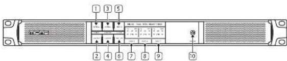
Front Panel Controls
- Port A optical - Button select and LED indicator.
- Port A copper - Button select and LED indicator.
- Port X-Y optical - Button select and LED indicator.
- Port X-Y copper Button select and LCD indicator.
-
Clock source Port A - Button select and LED indicator.
-
Clock source Port X-Y - Button select and LED indicator.
- Shows port A connection status Copper (Cu) and Optical (OPT).
- Shows port X connection status Copper (Cu) and Optical (OPT).
- Shows port Y connection status Copper (Cut) and Optical (OPT).
- Power indication - Blue when booting or if both PSUs are active. Purple if booted and one PSU is not powered.
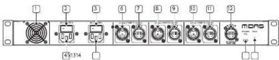
Rear Panel Controls
- Internal fan. Keep dear to allow air flow.
- Power On/Off switch for PSU 2.
- Power On/Off switch for PSU1.
- IEC power socket 2. Auto-ranging universal switch-mode power supply. 100 V - 240 V.
- IEC power socket 1. Auto-ranging universal switch-mode power supply. 100 V - 240 V.
-
Port Y Optical connection.
-
Port Y Copper connection.
- Port X Optical connection.
- Part X Copper connection.
- Port A Optical connection.
- Port A Copper connection.
- Ethernet Control port.
- Firmware upgrade port.
- System reset button.
20 AS 80
Quick Star Guide 21
AS 80 Controls
LED Status indicators:
- Pulsating Green – Link up, carrying audio and control.
- Fast flashing Green – Link down, cable connection detected.
- Flashing Red – Link down, hunting for sync on port.
- Red On - Link down, no cable detected, not hunting.
PortA
| Clock=Port A (clock received port A, clock transmitting port X/Y) | ||
| Green Red Port Status | ||
| Pulsating Off Link up, carrying audio and control. | ||
| Fast flashing Flashing Link down, Cable link up. Selected as clock source. | ||
| Off Flashing Unit down, No cable link. Selected as clock source. | ||
| Clock=Port X/Y (clock received port X/Y, clock transmitting port A) | ||
| Green Red Port Status | ||
| Pulsating Off Link up, carrying audio and control. | ||
| Fast flashing On/OFF Link down, Cable link up. | ||
| Off On Line down, No cable link. | ||
Ports X or Y
| Clock-Port X/Y (clock received port X/Y, clock transmitting port X/Y) | ||
| Green Red Port Status | ||
| Pulsating Off Link up, carrying audio and control. | ||
| On Off Link up and in standby. | ||
| Fast Fashing On/Off Link down, Cable link up. | ||
| Off On Line down, No cable link. | ||
| Clock-Port X/Y (clock received port X/Y, clock transmitting port X) | ||
| Green Red Port Status | ||
| Pulsating Off Link up, carrying audio and control. | ||
| On Off Link up and in standby. | ||
| Fast Fashing Flashing Link down, Cable link up. Selected as clock source. | ||
| Fast Fashing On Link down, Cable link up, Not selected as clock source. | ||
| Off Flashing Link down, No cable link. Selected as clock source. | ||
| Off On Line down, No cable link, but selected as clock source. | ||
Firmware
Updates to the AS BO can be found at https://cloud.midasconsoles.com/drive/firmware release notes will guide you through the update process. You can also update AS BO units via the HD Series consoles.
Functions
Press and hold the selection buttons for 4s to change a setting. Blue for selected, white for unselected.
Matching the length and cable types for the redundant connections will create the best conditions for lowest audio loss during a redundant switch over event.
AS 80 Example Set-ups

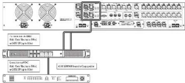
Redundant HMAC connection
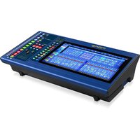
In this example the HD96-24 Console is located at the front of house position (FOH) and the AS 80 is located at the stage position with the DH5680. This allows either 2 Multi-Mode Fibre's or two Shielded CatSe STP cables to be used to connect the FOH console to the AS 80 giving redundancy of the HNAIC. Hypermac redundancy must be turned on in the HD96-24 console in order for this set-up to function correctly.
Note: When using redundant mode, the cables must be the same type, either 2 Fibre or 2 Shielded CatSe connections. You cannot use 1 fibre and 1 Shielded CatSe to achieve redundancy.
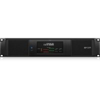
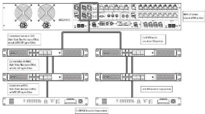
DUAL Redundant HMAC connection allowing 16 AES50 ports at stage
In this example the HD06-24 Console is located at the front of house position (FOH) with two AS 80's. This allows either 2 Multi-Mode Fibre's or two Shielded CatSe STP cables to connect the FOH console to the 2 local AS 80. The FOH AS 80's connect to the stage AS 80's with 2 Multi-Mode Fibre's or two Shielded CatSe STP cables giving redundancy of the HVAC. At the stage position the AS 80's are located with a DNP680 attached to each in order to connect to the stage 100. This gives a possible 16 A550 ports (up to 24 inputs and 24 outputs per port) with a pool of a possible 3B4 inputs depending on connected I/O.
flowchart
graph TD
    A["Server Rack"] --> B["Module 1"]
    A --> C["Module 2"]
    A --> D["Module 3"]
    A --> E["Module 4"]
    A --> F["Module 5"]
    A --> G["Module 6"]
    A --> H["Module 7"]
    A --> I["Module 8"]
    A --> J["Module 9"]
    A --> K["Module 10"]
    A --> L["Module 11"]
    A --> M["Module 12"]
    A --> N["Module 13"]
    A --> O["Module 14"]
    A --> P["Module 15"]
    A --> Q["Module 16"]
    A --> R["Module 17"]
    A --> S["Module 18"]
    A --> T["Module 19"]
    A --> U["Module 20"]
    A --> V["Module 21"]
    A --> W["Module 22"]
    A --> X["Module 23"]
    A --> Y["Module 24"]
    A --> Z["Module 25"]
    A --> AA["Module 26"]
    A --> AB["Module 27"]
    A --> AC["Module 28"]
    A --> AD["Module 29"]
    A --> AE["Module 30"]
    A --> AF["Module 31"]
    A --> AG["Module 32"]
    A --> AH["Module 33"]
    A --> AI["Module 34"]
    A --> AJ["Module 35"]
    A --> AK["Module 36"]
    A --> AL["Module 37"]
    A --> AM["Module 38"]
    A --> AN["Module 39"]
    A --> AO["Module 40"]
    A --> AP["Module 41"]
    A --> AQ["Module 42"]
    A --> AR["Module 43"]
    A --> AS["Module 44"]
    A --> AT["Module 45"]
    A --> AU["Module 46"]
    A --> AV["Module 47"]
    A --> AW["Module 48"]
    A --> AX["Module 49"]
    A --> AY["Module 50"]
    A --> AZ["Module 51"]
    A --> BA["Module 52"]
    A --> BB["Module 53"]
    A --> BC["Module 54"]
    A --> BD["Module 55"]
    A --> BE["Module 56"]
    A --> BF["Module 57"]
    A --> BG["Module 58"]
    A --> BH["Module 59"]
    A --> BI["Module 60"]
    A --> BJ["Module 61"]
    A --> BK["Module 62"]
    A --> BL["Module 63"]
    A --> BM["Module 64"]
    A --> BN["Module 65"]
    A --> BO["Module 66"]
    A --> BP["Module 67"]
    A --> BQ["Module 68"]
    A --> BR["Module 69"]
    A --> BS["Module 70"]
    A --> BT["Module 71"]
    A --> BU["Module 72"]
    A --> BV["Module 73"]
    A --> BW["Module 74"]
    A --> BX["Module 75"]
    A --> BY["Module 76"]
    A --> BZ["Module 77"]
    A --> CA["Module 78"]
    A --> CB["Module 79"]
    A --> CC["Module 80"]
22 AS AG Quick Stay Guide 23
Specifications
| Connectors | |
| Snake ports copper 3 x FL-45 Hyper MAC | |
| Snake ports optical 3 x optical connector DDD Multil Mode | |
| Ethernet control 1 x Ethernet control port for RADS connector | |
| Upgrade port 1 x Micron USB | |
| Power Requirements | |
| Maine power inier 2 x 3-pin IEC switched connector | |
| Power consumption 25 VU x 2 | |
| Voltage 100 VAC to 240 VAC ± 10% | |
| Physical | |
| Dimensions (ft x 19 x 10 44 x 481 x 436 mm (1.7 x 19 x 3.7") | |
| Net Weight: 5.1 kg (11.2 lbs) | |
| Strapping Weight: 7.1 kg (13.6 lbs) | |
| Temperature Range | |
| Operating temperature range 41 to 113°F (5 to 45°C) | |
| Storage temperature range | -1 to 100°F (-20 to 60%) |
EN
24 AS AG Quick Start Guide 25
AS 80 Introducción
¡Bienvenidol
flowchart
graph TD
    A["Network Switch"] --> B["Control Panel"]
    B --> C["1.0x 80% wireless network (60%)"]
    B --> D["2.0x 80% wireless network (50%)"]
    B --> E["3.0x 80% wireless network (40%)"]
    B --> F["4.0x 80% wireless network (30%)"]
    B --> G["5.0x 80% wireless network (20%)"]
    B --> H["6.0x 80% wireless network (10%)"]
Specifiche
Thank you for purchasing the AS 80 HMAC to dual HMAC converter!
About this QSG/manual
This is the quick start guide and operation manual for the AS 80. This manual is intended to help get your unit installed and in operation as quickly as possible by giving you unpacking, installation, connection, setting up and operating instructions.
AS 80 Aan de slag
Uitpakken
To help familiarise you with the AS 80, there is a description of the front and rear panels, along with easy-to-follow user instructions.
Voeding
LED Status indicators:
- Pulsating Green - Link up, carrying audio and control.
- Fast flashing Green – Link down, cable connection detected.
- Flashing Red - Link down, hunting for sync on port
• Red On - Link down, no cable detected, not hunting.
PortA
| Clock=Port A (clock received Port A, clock transmitting port X/Y) | ||
| Green Red Port Status | ||
| Pulsating Off Link up, carrying audio and control. | ||
| Fast flashing Flashing Link down, Cable link up. Selected as clock source. | ||
| Off Flashing Unit down, No cable link. Selected as clock source. | ||
| Clock=Port X/Y (clock received port X/Y, clock transmitting port A) | ||
| Green Red Port Status | ||
| Pulsating Off Link up, carrying audio and control. | ||
| Fast flashing On/OFF Link down, Cable link up. | ||
| Off On Line down, No cable link. | ||
Ports X or Y
| Clock-Port X/Y (clock received port X/Y, clock transmitting port X/Y) | ||
| Green Red Port Status | ||
| Pulsating Off Link up, carrying audio and control. | ||
| On Off Link up and in standby. | ||
| Fast Fashing On/Off Link down, Cable link up. | ||
| Off On Line down, No cable link. | ||
| Clock-Port X/Y (clock received port X/Y, clock transmitting port X) | ||
| Green Red Port Status | ||
| Pulsating Off Link up, carrying audio and control. | ||
| On Off Link up and in standby. | ||
| Fast Fashing Flashing Link down, Cable link up. Selected as clock source. | ||
| Fast Fashing On Link down, Cable link up, Not selected as clock source. | ||
| Off Flashing Link down, No cable link. Selected as clock source. | ||
| Off On Line down, No cable link, but selected as clock source. | ||
Firmware
Updates to the AS BO can be found at https://cloud.midasconsoles.com/drive/firmware release notes will guide you through the update process. You can also update AS BO units via the HD Series consoles.
Functions
Press and hold the selection buttons for 4s to change a setting. Blue for selected, white for unselected.
Matching the length and cable types for the redundant connections will create the best conditions for lowest audio loss during a redundant switch over event.
flowchart
graph TD
    A["Central Control Panel"] --> B["1.0 Ethernet Connection"]
    A --> C["2.0 Ethernet Connection"]
    A --> D["3.0 Ethernet Connection"]
    A --> E["4.0 Ethernet Connection"]
    B --> F["1.0 Ethernet Interface"]
    C --> G["2.0 Ethernet Interface"]
    D --> H["3.0 Ethernet Interface"]
    E --> I["4.0 Ethernet Interface"]
Especificações
EN Other important information
ES
EN Important information
1. Product Registration
To ensure optimal service and support, we encourage you to register your Music Tribe product immediately after purchase at musictric.com. Registration allows us to provide faster and more efficient assistance in the event of a service request or warranty claim. It also ensures that you receive important product updates, safety notices, and documentation relevant to your product.
DE
During registration, you will also have access to the full terms and conditions of our Limited Warranty.
Please note that warranty coverage and consumer rights may vary by country or jurisdiction. Refer to the terms applicable in your region at the time of registration or via our support portal.
FR
- Technical Support and Malfunctions If you experience a malfunction or require assistance, and a Music Tribe Authorized Reseller is not available in your area, please refer to the list of Authorized Fulfilers available under the "Support" section at musictribe.com.
If your country is not listed, we recommend using our Online Support resources as a first step, which may help resolve your issue without the need for a return. For warranty-related matters, please ensure you submit an online warranty claim before returning the product. Unauthorized returns or unregistered claims may result in processing delays or denial of warranty coverage.
3. Unauthorized Repairs and Modifications
To preserve warranty coverage, do not open, disassemble, or attempt to repair the product yourself. Repairs or modifications performed by unauthorized persons or service centers will void the warranty and may compromise product safety or performance.
Before connecting your unit to a power source, ensure that the input voltage matches the rating indicated on your product. Incorrect voltage may cause permanent damage and void the warranty.
If the fuse requires replacement, only use fuses of the same type and rating. Use of incorrect fuses may create a fire or safety hazard and will invalidate all warranty protection.
- Proper Use and Environment Ensure that your Music Tribe product is used in accordance with the product manual and within the recommended operating conditions. Exposure to excessive moisture, dust, heat, or impact may result in malfunction and void the warranty.
Other important information

Ważna informacja

Correct disposal of this product: This symbol indicates that this product must not be disposed of with household waste, according to the WEEE Directive (2012/19/EU) and your national law. This product should be taken to a collection center licensed for the recycling of waste electrical and electronic equipment (EEF). The mishandling of this type of waste could have a possible negative impact on the environment and human health due to potentially hazardous substances that are generally associated with EEF. At the same
time, your cooperation in the correct disposal of this product will contribute to the efficient use of natural resources. For more information about where you can take your waste equipment for recycling, please contact your local city office, or your household waste collection service.
Responsible Party Name: Empower Tribe Innovations
US Inc.
Address: 901 Grier Dr. Las Vegas, NV, 89119, USA
Email Address: legal@musictribe.com
AS 80
This equipment has been tested and found to comply with the limits for a Class B digital device, pursuant to part 15 of the FCC Rules. These limits are designed to provide reasonable protection against harmful interference in a residential installation. This equipment generates, uses and can radiate radio frequency energy and, if not installed and used in accordance with the instructions, may cause harmful interference to radio communications. However, there is no guarantee that interference will not occur in a particular installation. If this equipment does cause harmful interference to radio or television reception, which can be determined by turning the equipment off and on, the user is encouraged to try to correct the interference by one or more of the following measures:
• Resient or relocate the receiving antennas.
- Increase the separation between the equipment and receiver.
- Connect the equipment into an outlet on a circuit different from that to which the receiver is connected.
- Consult the dealer or an experienced radio/TV technician for help.
This equipment complies with Part 15 of the FCC rules. Operation is subject to the following two conditions:
(1) this device may not cause harmful interference, and (2) this device must accept any interference received. Including interference that may cause undesired operation.
Important information:
Changes or modifications to the equipment not expressly approved by Music Tribe can void the user's authority to use the equipment.
CE
Hersby, Music Tribe declares that this product is in compliance with Directive 2014/35/EU, Directive 2014/30/EU, Directive 2011/65/EU and Amendment 2015/B63/EU, Directive 2012/19/EU, Regulation 519/2012 REACH SVHC and Directive 1907/2006/L.
Full text of EU DeC is available at https://community.musictribe.com/
EU Representative: Empower Tribe Innovations DE GmbH
Address: Otto Brenner Strasse 4a, 47877 Willich, Germany
UK Representative: Empower Tribe Innovations UK Ltd
Address: 5 Brindley Road Old Trafford, Manchester, United Kingdom, M16 SUN
Quick Star Guide
89