
FiltoClear 13000 - Water filter OASE - Free user manual and instructions
Find the device manual for free FiltoClear 13000 OASE in PDF.

| Product type | Pressurized water filter for garden pond |
| Brand | Oase |
| Model | FiltoClear 13000 |
| Maximum pond volume | 13000 liters (without fish), 7000 liters (with fish) |
| Dimensions (L × W × H) | 391 × 382 × 490 mm |
| Weight (dry) | 8.8 kg |
| Weight (in water) | 36 kg |
| Power supply | 220-240 V AC, 50/60 Hz |
| Power consumption (UVC) | 24 W |
| UVC lamp | 24 W TC-L (UV-C), lifetime 8000 h |
| Maximum flow rate | 9000 l/h |
| Maximum permissible pressure | 0.2 bar (service), 0.6 bar (pump) |
| Inlet/outlet connection | G2, hose 38 or 50 mm |
| Protection rating | IP68 (waterproof up to 0.1 m) |
| Permissible water temperature | +4 to +35 °C |
| Number of filter sponges | 3 (1 red 30 ppi, 1 blue 10 ppi, 1 purple 20 ppi) |
| Main functions | Mechanical and biological filtration, UVC clarification, Easy-Clean cleaning |
| Maintenance | Cleaning sponges by pulling handle, rinsing with clear water |
| Safety | Differential protection device 30 mA, safety lock, automatic shutdown in case of overheating |
| Spare parts | UVC lamp, quartz glass, filter sponges, cleaning rotor |
Frequently Asked Questions - FiltoClear 13000 OASE
User questions about FiltoClear 13000 OASE
0 question about this device. Answer the ones you know or ask your own.
Ask a new question about this device
Download the instructions for your Water filter in PDF format for free! Find your manual FiltoClear 13000 - OASE and take your electronic device back in hand. On this page are published all the documents necessary for the use of your device. FiltoClear 13000 by OASE.
USER MANUAL FiltoClear 13000 OASE
natural_image
Four black industrial filter units with blue and gray components, arranged in a row (no text or symbols visible)FiltoClear
5000, 13000, 19000, 31000
EN Operating instructions
FR Notice d'emploi
FCL0007
1

natural_image
Technical line drawing of a spray gun with height dimension labeled 'h' (no text or symbols beyond the label)| FiltoClear | Eingrabtiefe h |
| 5000 | 0,12 m |
| 13000 | 0,24 m |
| 19000 | 0,36 m |
| 31000 | 0,48 m |
FCL0014
FCL0028
HINWEIS
natural_image
Technical illustration of a mechanical device with a close-up view showing internal components (no text or symbols)FCL0015
Betrieb
FCL0020
FCL0018

FCL0019
FCL002
Reinigen
natural_image
Technical line drawing of a cylindrical device with mesh structure and internal components (no text or symbols)FCL0030
FCL0021
Verschleißteile
▶ Disconnect all electrical units in the water from the power supply before reaching into the water. Otherwise there is a risk of injuries or death by electrocution.
This unit can be used by children aged 8 and above and by persons with reduced physical, sensory or mental capabilities or lack of experience and knowledge if they are supervised or have been instructed on how to use the unit in a safe way and they understand the hazards involved. Do not allow children to play with the unit. Only allow children to carry out cleaning and user maintenance under supervision.
Safety information
Electrical connection
- Special regulations apply to electrical installation in outdoor areas. Only allow a qualified electrician to perform the electrical installation.
— The qualified electrician has the required professional training, knowledge and skills to perform electrical installations in outdoor areas. The qualified electrician can detect potential risks and adheres to regional and national standards, regulations and directives.
- For your own safety, please consult a qualified electrician.
- Only connect the unit if the electrical data of the unit and the power supply match.
- Only connect the device to a correctly installed socket.
- The device is to be supplied through a residual current device (RCD) having a rated residual operating current not exceeding 30 mA.
- Extension cables and power distributors (e.g. outlet strips) must be suitable for outdoor use (splash-proof).
- Protect open plugs and sockets from moisture.
Safe operation
- Do not use the unit, if electrical lines or the housing are damaged.
- Dispose of the unit if its power connection cable is damaged. The power connection cable cannot be replaced.
- Do not carry or pull the unit by its power cable.
- Never make technical modifications to the unit.
- Only carry out work on the unit that is described in this manual.
- Only use original spare parts and accessories.
- Route lines so that they are protected from damage and nobody can trip over them.
- Should problems occur, please contact the authorized customer service or OASE.
Intended use
Only use the product described in this manual as follows:
- For mechanical and biological cleaning of garden ponds
- In compliance with the technical specifications. (→ Technical data)
The following restrictions apply to the unit:
- This product is not suitable for general lighting, but is only intended for the purpose described here.
- Never operate the UVC lamp outside the casing or use it for any other purpose. The UVC radiation is harmful to the eyes and skin even in small doses.
- Never use the unit with fluids other than water.
- Do not use in conjunction with chemicals, food, easily flammable or explosive substances.
- Never run the unit without water.
- Do not use for industrial purposes.
Product description
Overview
EN
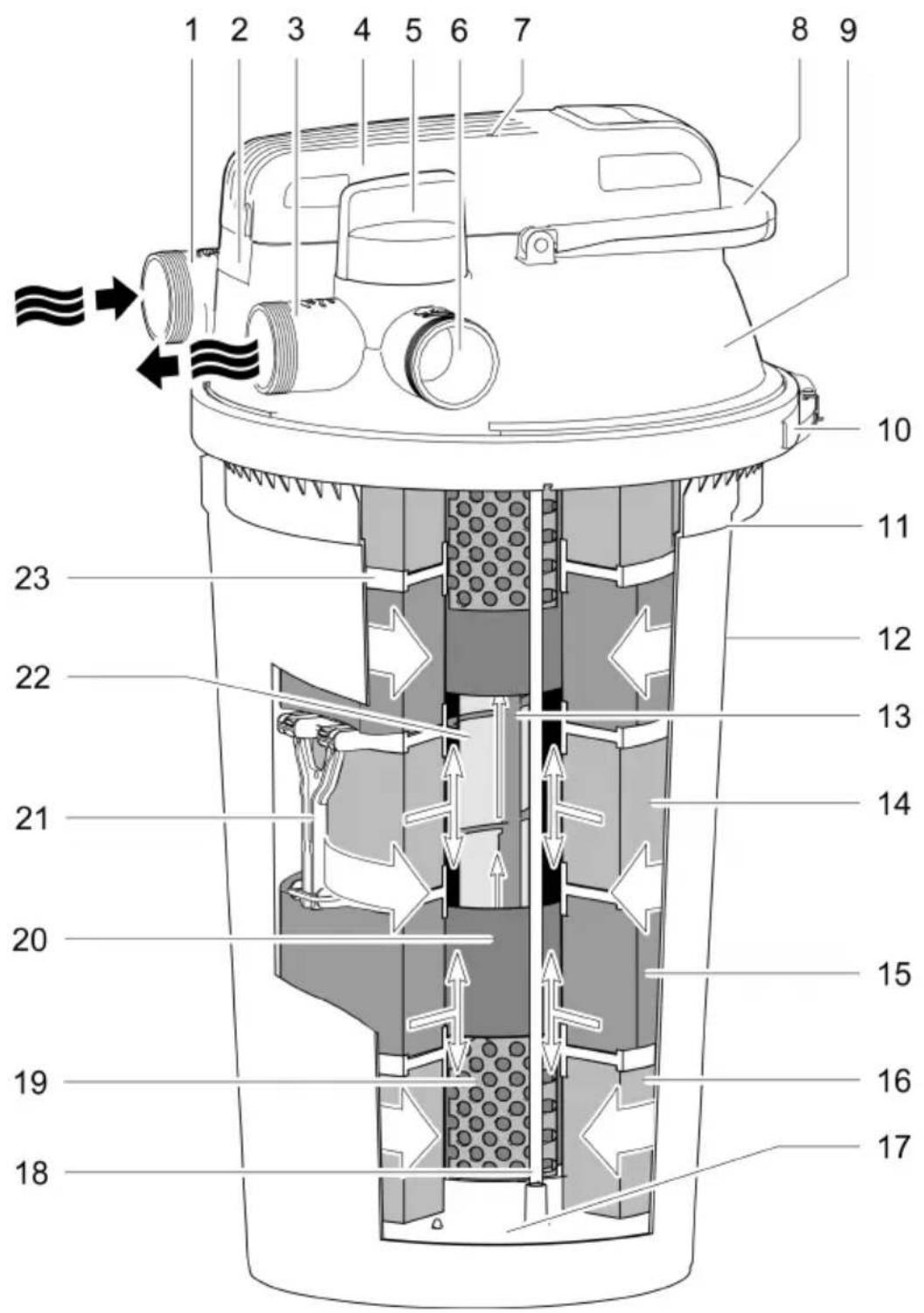
FCL0007
1

Water inlet for the pond water being cleaned
- Connection G2
2
Opening ring with locking screw for locking the UVC unit head
- It is necessary to open the opening ring in order to remove the UVC unit head.
3

Water outlet for the cleaned pond water
- Connection G2
4
UVC unit head with temperature monitor
- The UVC clarifier shuts down when overheating and automatically turns on again after it has cooled down
5
Turning valve for switching between water outlet and dirt water outlet

Water filtration and UVC radiation

Cleaning the foam filters
6

Dirt water outlet for the dirt water when cleaning the foam filters
- Connection G2
7
Indicator lamp for checking the function of the UVCclarifier
8
Cleaning handle
- Pull to compress the foam filters and flush out the dirt particles
9
Filter cover
10
Clamping ring for fastening the filter cover on the container
11
Marking for max. burying depth
12
Container
13
Cleaning rotor, cleans the quartz glass during operation
• Only for FiltoClear 19000, 31000
14
Foam filter, blue (10 ppi)
15
Foam filter, red (30 ppi)
16
Foam filter, purple (20 ppi)
17
Closing disc for foam filters, is connected with both cleaning rods
18
Cleaning rod, connecting cleaning handle and closing disc
19
Meshed tube, maintaining the distance between the foam filters and the UVC water housing
2
UVC water housing, conveying water to the UVC lamp
2
Spacers that connect the two spacer discs
- The spacers prevent the foam filters from being compressed by the weight of the foam filters above them
2
Quartz glass with internal UVC lamp
23
Spacer disc, placed between each pair of foam filters
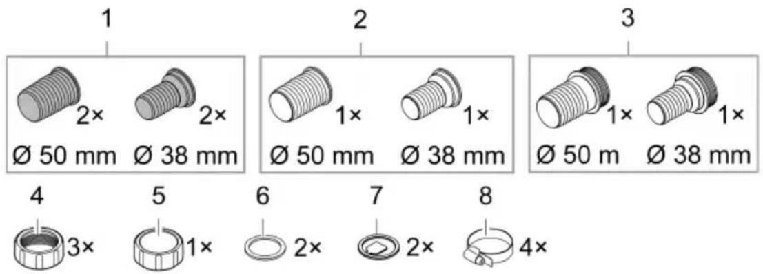
Connection components for installation
EN
FCL0012
1 Hose connector, transparent
• Use: Water outlet, dirt water outlet
2 Hose connector, black
- Use: Water inlet
3 Hose connector, black with G2 outer thread
- Use: Open end of the dirt water hose, the cover cap is screwed onto the outer thread
4 Union nuts G2, for installing the hose connectors
5 Cover cap G2, for closing the dirt water outlet
6 Flat seal for black hose connector and cover cap
7 Flow lug for transparent hose connector
8 Hose clip
Function description
The filter pump pushes the water into the pressure-tight container where it passes through several cleaning stages before returning into the pond.
Cleaning stage "Filtration"
The water flows through the foam filters. Mechanical soiling is retained by the foam filters. Suspended matter and bio sludge settle on the container bottom. Useful bacteria settle on the foam filters, cleaning the water biologically. Their effect starts at a water temperature of +10 °C.
| Foam filter | Properties |
| Blue (10 ppi) | High flow rate |
| Purple (20 ppi) | Colonisation of bacteria for nitrification, which turns ammonia first into nitrite, then into nitrate |
| Red (30 ppi) | Lower flow rateColonisation of bacteria for nitrification and denitrification, which turns nitrate into nitrogen |
Cleaning stage "UVC radiation"
Water is subjected to UV-C light from the UVC clarifier. Green algae die, pathogenic agents are killed.
Bypass
The bypass ensures that only approx. 70 % of the water is subjected to UV-C light. This guarantees sufficient radiation even at high flow rates.
Biological cleaning effect
The maximum biological cleaning effect is achieved when the foam filters are fully colonised by filter bacteria. On new foam filters, colonisation may take several weeks. Adding starter bacteria can significantly speed up colonisation.
Cleaning the foam filters
You can use the soiled water from cleaning the foam filters to fertilise your garden.
Recommended filter pump
| FiltoClear | ||||
| 5000 | 13000 | 19000 | 31000 | |
| AquaMax Eco Premium | 5000 | 9000 | 13000 | 17000 |
Symbols on the unit
| IP68 0.1 m | The unit is dust-proof, fully protected against contact and protected from continuous immersion in water to a depth of 0.1 m. |
 | Dangerous UVC radiation |
 | Protect the unit from direct sunlight |
 | Protect the unit from freezing temperatures |
 | Do not dispose of the unit with normal household waste |
 | Read the operating [SEP] instructions |
Installation and connection
Installing the unit
To be taken into consideration for planning:
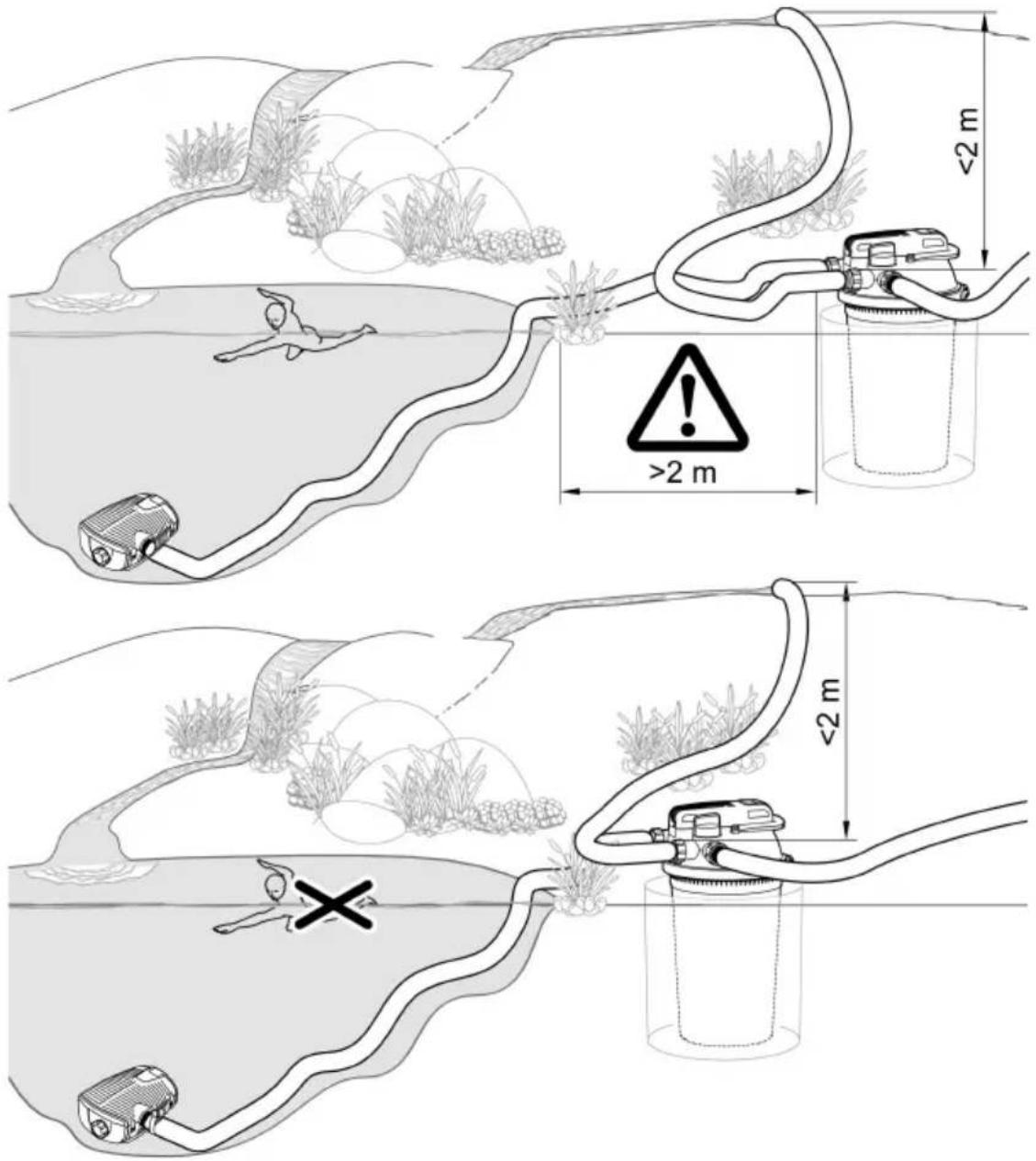
- For operation at a swimming pond: Install the unit at a distance of at least 2 m from the water.
- For operation at a pond: You can set up the unit directly at the edge of the pond.
- Protect the pressure filter from direct sunlight.
- Route the return hose into the pond so that the water returns to the pond e.g. through a water course. This enriches the water with additional oxygen.
- Ensure that the inlet into the pond is max. 2 m above the filter cover.
Burying the pressure filter
A buried container is barely visible. The stone grey FiltoCap (Art. No. 77831) cover available as an accessory for the filter cover fits seamlessly into the pond scape.
- Dig a hole close to the pond and place the container in the hole down to the maximum burying depth.
• The ground must be firm and horizontal.
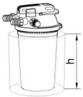
natural_image
Technical line drawing of a spray can with height dimension labeled 'h' (no text or symbols beyond the label)| FiltoClear | Burying depth h |
| 5000 | 0.12 m |
| 13000 | 0.24 m |
| 19000 | 0.36 m |
| 31000 | 0.48 m |
Installing the pressure filter on level ground
If you choose not to bury the pressure filter, position it so that it is hidden from sight e.g. covered by bushes.
• Install the unit near the pond.
- The ground must be firm and horizontal.
FCL0011
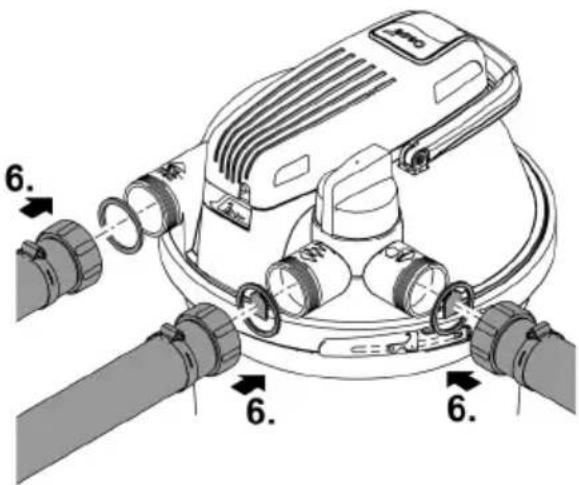
Establishing the connections
Hoses with a diameter of 38 mm or 50 mm can be connected to the pressure filter. The respective hose connectors are part of our scope of delivery.
Use hoses with a diameter of 50 mm to keep the pressure losses in the hoses as low as possible.
If you use a filter starter for start-up, fill the product into the container prior to carrying out the following installation steps.
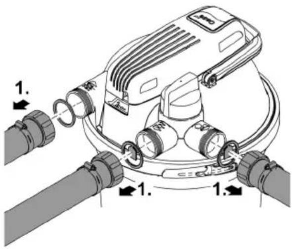
— It is easier to remove the filter cover if you first remove all hoses from the filter cover.
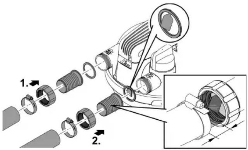
Connecting the inlet
Only use pressure hoses approved for at least the maximum pump pressure to connect the outlet of the filter pump and the inlet of the pressure filter.
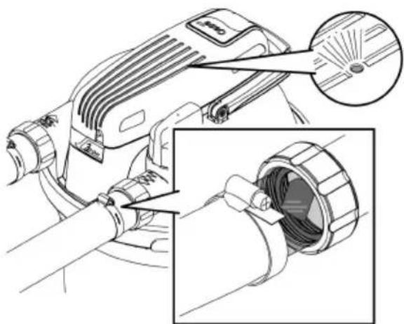
• Always use a hose clip to fasten the hose on a hose connector.
Connecting the outlet
Use a transparent hose connector with a flow lug. The transparent hose connector will allow you to assess the water quality after filtration. The flow lug will show you the water flow.
- Push the hose onto the hose connector until only two segments on the hose connector remain uncovered.
— This will give you a sufficiently large view into the hose connector.
• Always use a hose clip to fasten the hose on a hose connector.
FCL0014
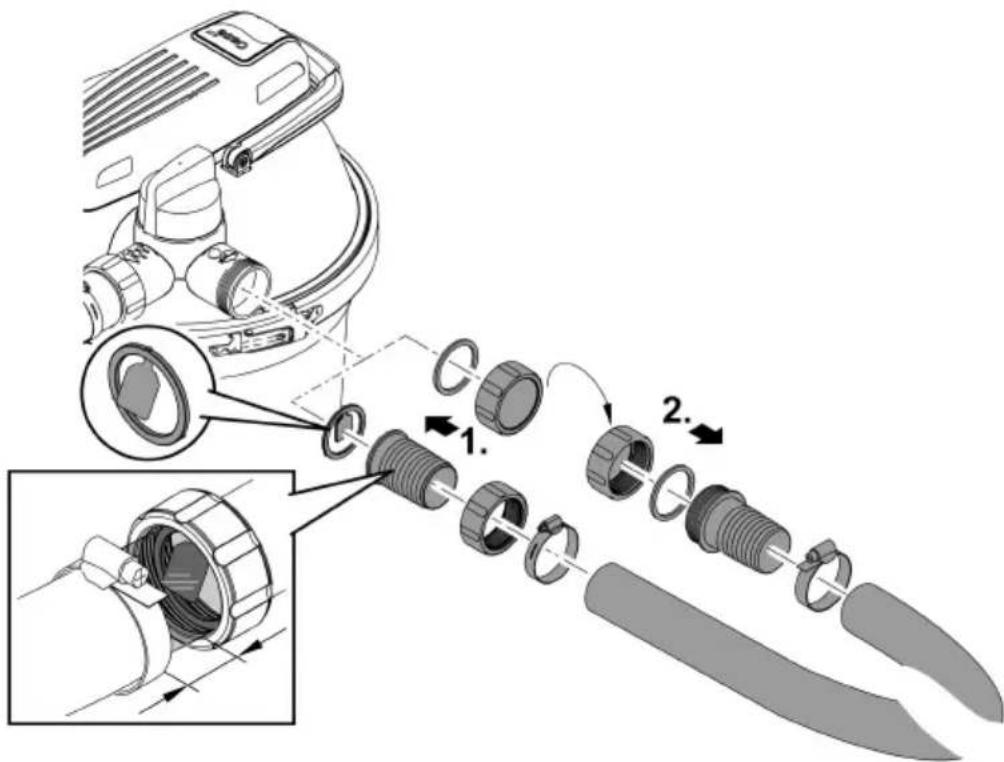
Connecting the dirt outlet
The soiled water resulting from cleaning can be used for fertilisation. Connect a hose and route it up to a suitable location (e.g. flower bed).
Use a transparent hose connector with a flow lug. The transparent hose connector will allow you to assess the degree of soiling of the water when cleaning the foam filters. The flow lug will show you the water flow.
- Push the hose onto the hose connector until only two segments on the hose connector remain uncovered.
— This will give you a sufficiently large view into the hose connector.
• Always use a hose clip to fasten the hose on a hose connector. - Install the black hose connector with the G2 outer thread on the outlet of the hose. Close the hose connector with the cover cap and the flat seal.
NOTE
Close the dirt outlet or the outlet of the connected hose with the cover cap and the flat seal. This prevents unintended emptying of the pond. Only remove the cover cap to drain dirty water.
FCL0028
NOTE
The unit will be destroyed if it is operated with a dimmer. It contains sensitive electrical components.
▶ Do not connect the unit to a dimmable power supply.
The purely biological starter bacteria Oase AquaActiv BioKick activate the filter biology and ensure maximum performance of your pond filter within only a few weeks. They immediately start removing nitrite, ammonium and ammonia from the water. We recommend filling the container with Oase AquaActiv BioKick
– during initial start-up,
— after manual cleaning or replacing the foam filters,
— after long shut-down periods or during start-up after a long winter break.
Start-up sequence:
- If required, fill the container with Oase AquaActiv BioKick. (→Removing/positioning the filter cover)
- Ensure that the hoses, cover cap for the dirt water outlet and the clamping ring with the safety latch are firmly connected.
- Turn the turning valve to "Filter water".
- Switch on the pond pump.
- Only switch on the UVC clarifier when water emerges from the water outlet. (→ Switching the UVC clarifier on/off)
- Never run the UVC clarifier without water flowing through.
- If you are using Oase AquaActiv BioKick, leave the UVC clarifier turned off for 24 hours. This allows the starter bacteria to achieve optimum effectiveness.
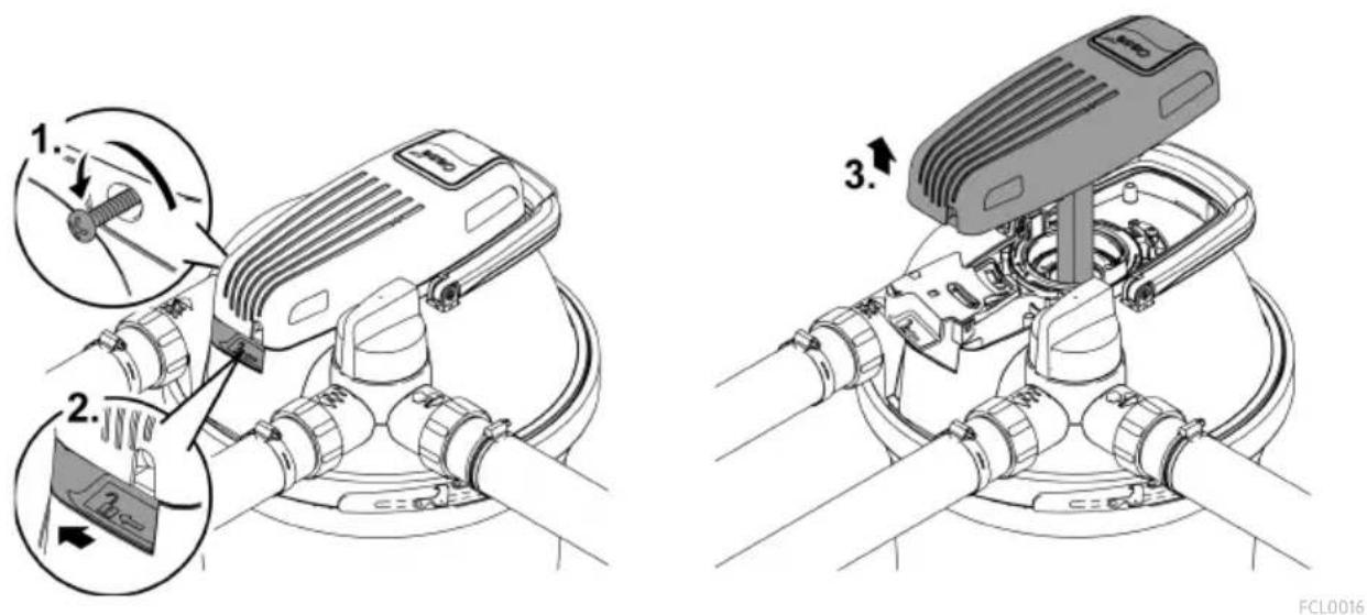
Switching the UVC clarifier on/off
- Switching on: Plug the power plug into the outlet.
— The unit switches on immediately. - The indicator lamp lights up.
— The flow lug on the outlet will show you that water is flowing. - Switching off: Pull the power plug from the outlet.
natural_image
Technical illustration of a mechanical device with a close-up view showing internal components (no text or symbols)FCL0015
Operation
The pressure filter can remain in operation for the full pond season (the filter pump and the UVC clarifier are switched on).
- The biological filter elements are no longer active at water temperature of less than 10^ .
- Shut down the unit at water temperatures below 8 °C or at the latest when freezing temperature are to be expected. (→Decommissioning/winter storage)
- The UVC lamp is a wear part. Replace the UVC lamp after a specific operating duration to ensure optimum filter performance. (→ Replacing the UVC lamp)
Maintenance and cleaning
NOTE
Do not use aggressive cleaning agents or chemical solutions. These agents can damage the housing, impair the function of the device and harm animals, plants and the environment.
▶ Only clean the unit from the outside with clear water and a soft brush.
Cleaning the foam filters
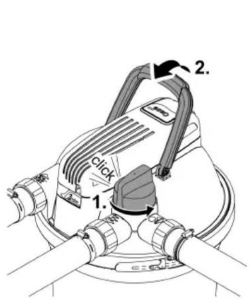
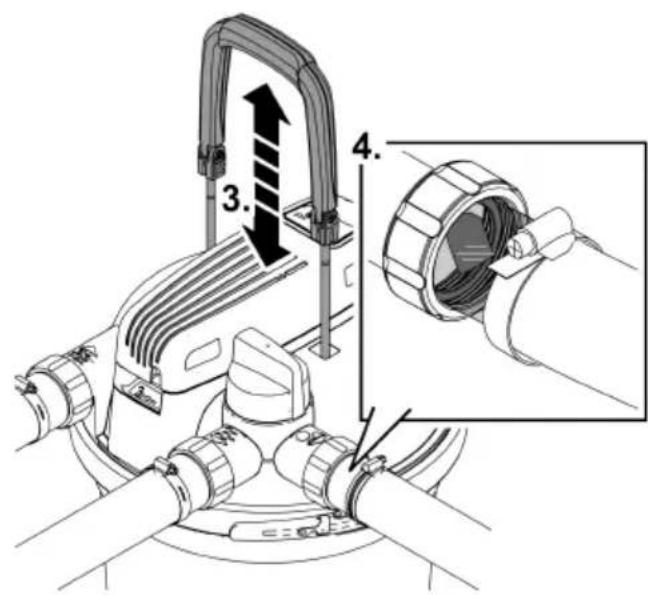
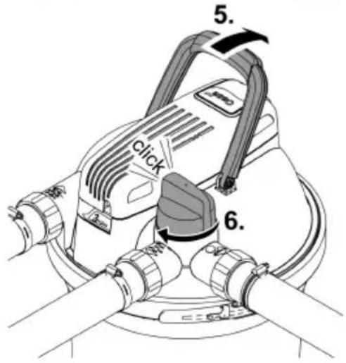
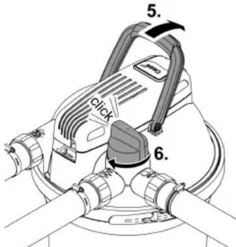
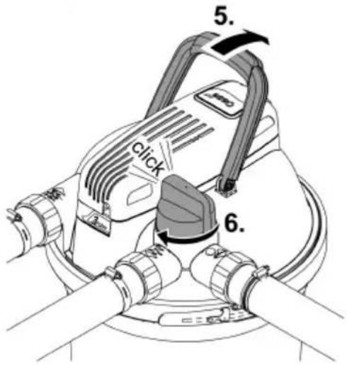
The Easy Clean function is used to clean the foam filters. During cleaning, the filter pump is switched on so that the dirt water is transported out of the pressure filter.
- Turn the turning valve to guide the water in the container to the dirt water outlet. This prevents the dirt water from flowing back into the pond.
— Beforehand, remove the cover cap from the outlet hose for the dirt water. - Pull the cleaning handle to compress the foam filters. The dirt particles are removed and flow with the water via the dirt water outlet, for instance to a flower bed.
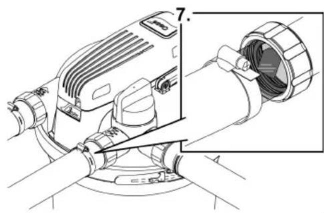
- The transparent hose connectors allow you to check the water flow and assess the degree of soiling in the water during cleaning on the dirt water outlet. As soon as the water runs clear, turn the turning valve back to "Filtering".
- After cleaning, close the dirt water hose or the dirt water outlet with the cover cap and the flat seal.
FCL0020
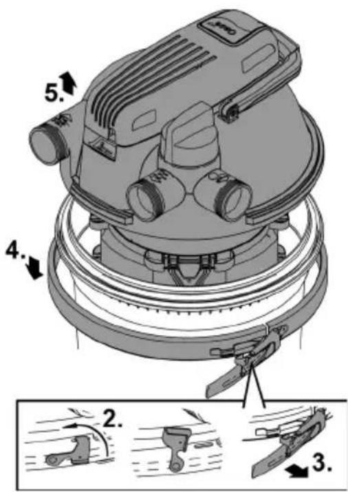
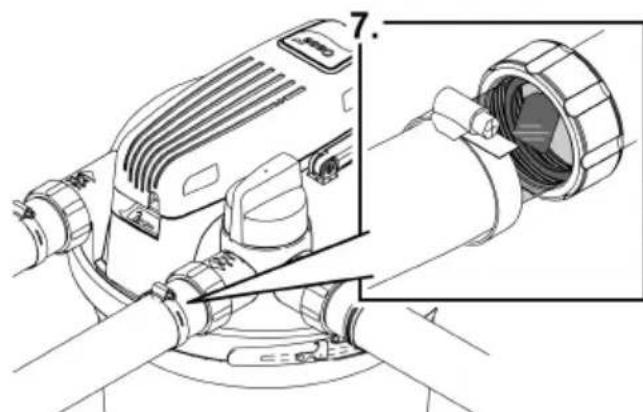
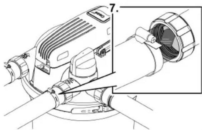
Removing/positioning the filter cover
Removing the filter cover
How to proceed:
- Switch off the filter pump and pull the power plug of the UVC clarifier from the outlet.
- Remove all hoses from the filter cover (unscrew hose connectors).
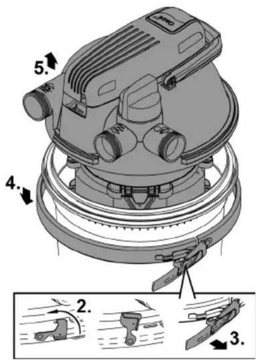
- Undo the locking latch.
- Use flat nose pliers if the locking latch is hard to move.
- Open the clamping ring and remove the filter cover.
FCL0018
Positioning the filter cover
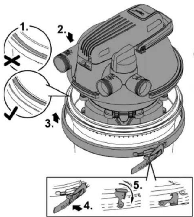
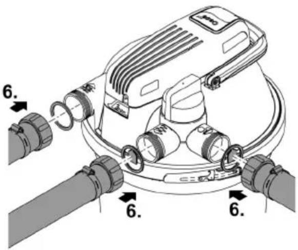
- Ensure that the O-ring on the container is positioned correctly on the container rim.
- Moisten the seal with water or grease the seal, if necessary, so that the filter head is easier to push onto the container.
- Evenly and forcefully push the filter cover as far as possible onto the container.
- The filter ring must make full contact with the container, otherwise the clamping ring will not close.
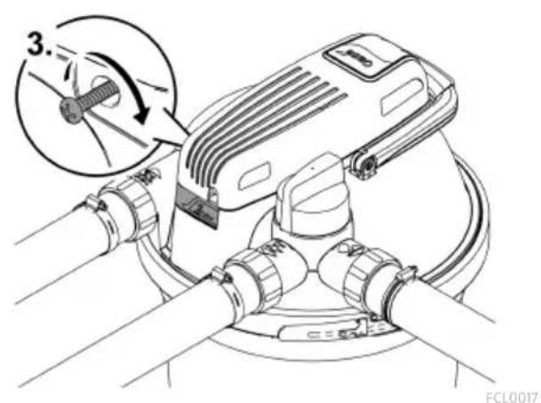
- Fasten the filter cover with the clamping ring and close the locking latch.
— The locking latch prevents the clamping ring from coming loose accidentally, which would cause pond water to leak in an uncontrolled manner.
— Use flat nose pliers if the locking latch is hard to move. - Attach all hoses (screw hose connectors in place).

FCL0019
Cleaning the unit and washing or replacing the foam filters
Wear of the foam filters is caused by mechanical stress and normal ageing.
i Insert new foam filters at the start of the season.
Disassembling the foam filter package
Prerequisite:
- The filter cover has been removed. (→Removing the filter cover)
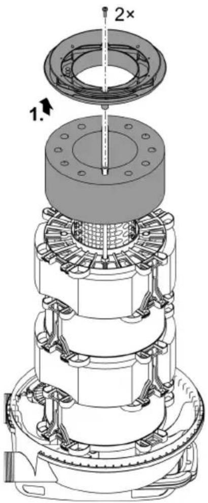
Place the filter cover upside down on a soft clean surface so that the foam filter package is on top.
- Undo the two screws, remove the closing disc and remove the first foam filter.
- For every additional foam filter, undo the two spacers and remove the spacer disc and the foam filter.

FCL0023
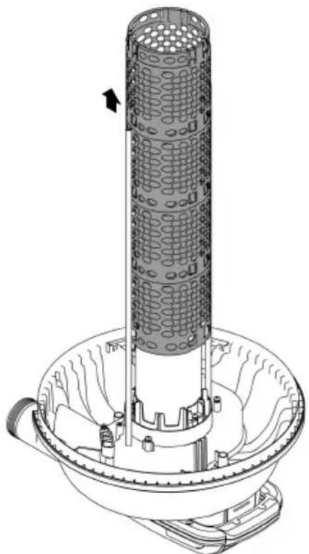
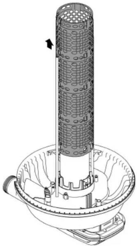
Cleaning
- Clean the container, the clamping ring, the filter cover, the UVC water housing and the meshed tube with a powerful water jet.
— Pull off the meshed tube by pulling and simultaneously turning it clockwise. - Wash each of the foam filters by forcefully compressing it under running water.
- If necessary, replace the foam filters.
natural_image
Technical line drawing of a vertical cylindrical device mounted on a base, with no visible text or symbols.EN
FCL0030
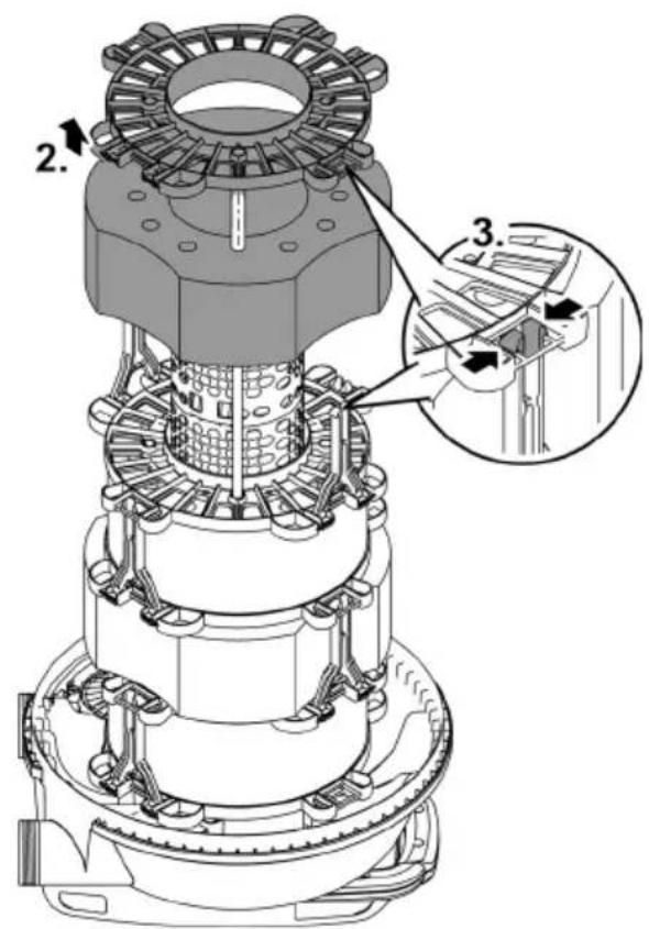
Assembling the foam filter package
- Push the foam filters onto the meshed tube in the intended order. (→Installation sequence of the foam filters)
- Place a spacer disc on each foam filter and fasten it with two spacers each.
- Insert the spacer into the spacer disc up to the stop and fold over the spacer with a slight rotary movement.
- Place the closing disc on the final foam filter (purple, 20 ppi). Fasten the closing disc to the two cleaning rods using the two screws.
- Position the filter cover on the container. (→ Positioning the filter cover)
FCL0024
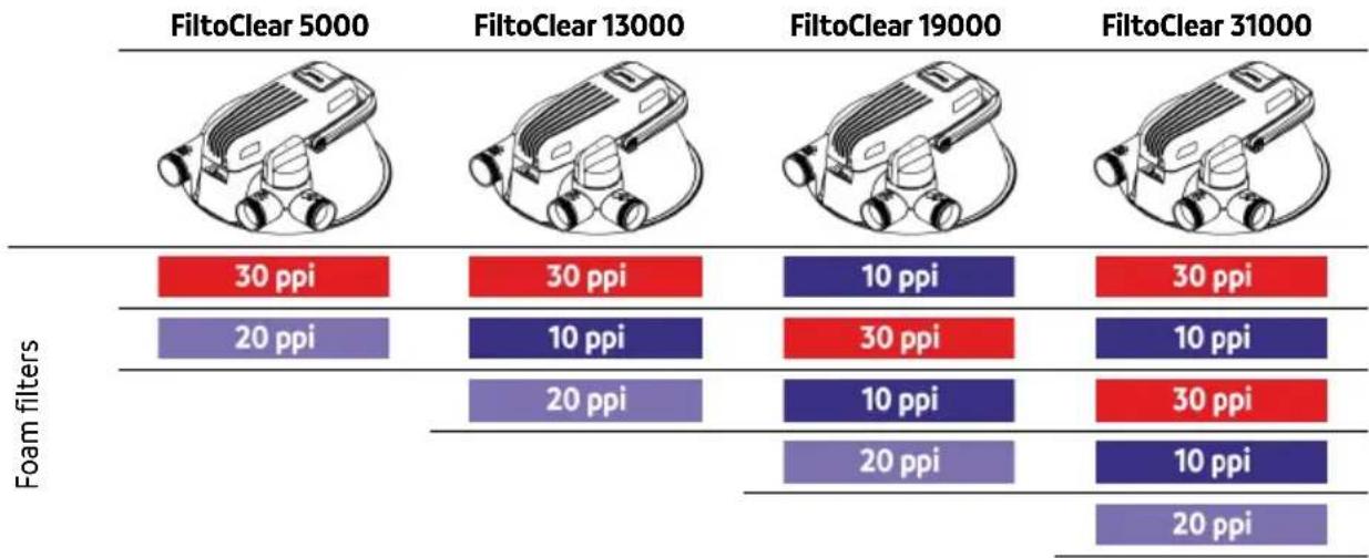
Installation sequence of the foam filters
other
| Foam filters | FiltoClear 5000 | FiltoClear 13000 | FiltoClear 19000 | FiltoClear 31000 | |---|---|---|---|---| | | 30 ppi | 30 ppi | 10 ppi | 30 ppi | | | 20 ppi | 10 ppi | 30 ppi | 10 ppi | | | | 20 ppi | 10 ppi | 30 ppi | | | | | 20 ppi | 10 ppi | | | | | | 20 ppi |Removing/installing the UVC unit head

CAUTION
The ultra-violet radiation of the UVC lamp can damage your eyes and skin.
▶ Never operate the UVC lamp outside out the casing or in a damaged casing.
▶ Disconnect the unit from the power grid before starting any maintenance work or before replacing the UVC lamp.

CAUTION
The quartz glass and UVC lamp could break and cause cuts.
▶ Act with caution when performing work on the UVC clarifier in order to avoid cuts.
▶ Avoid shocks, impacts and abrupt movements to prevent the glass from breaking.
For safety reasons, the UVC lamp can only be turned on when the UVC clarifier is properly installed in the unit.
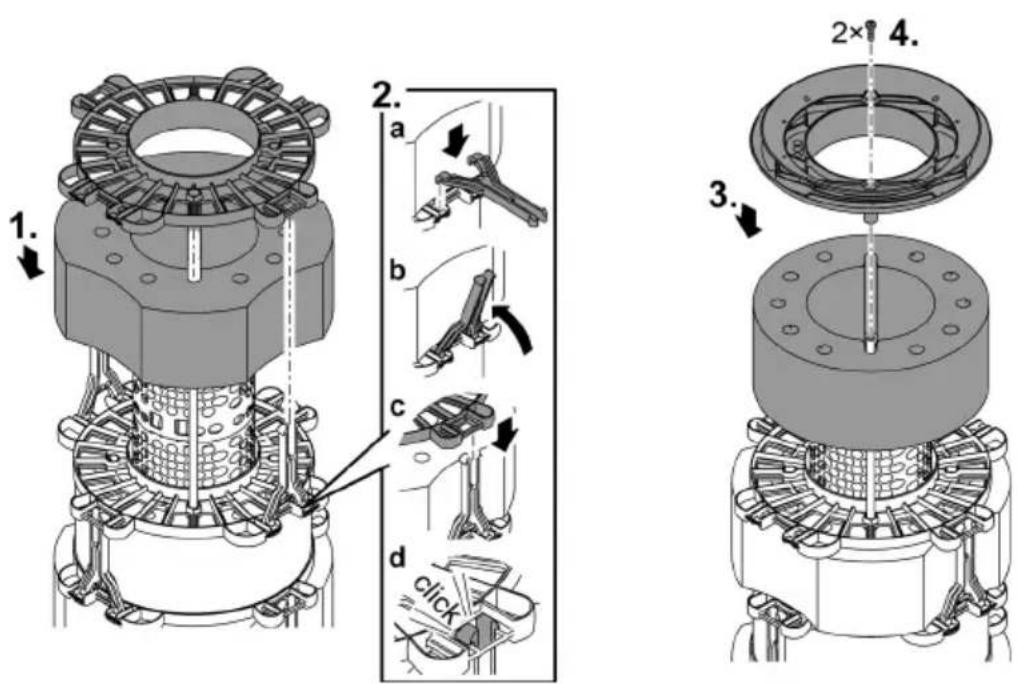
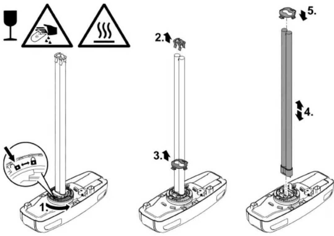
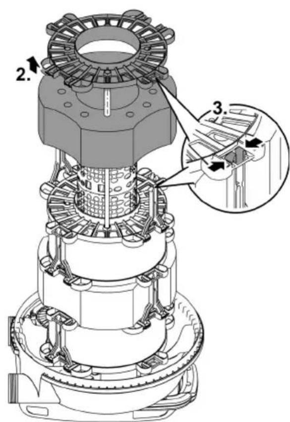
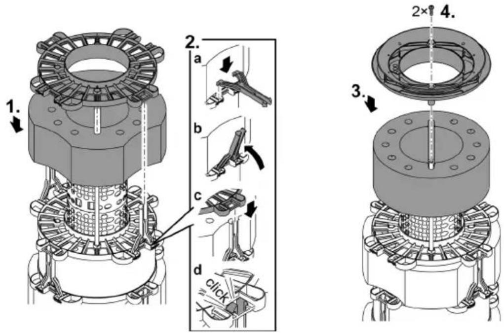
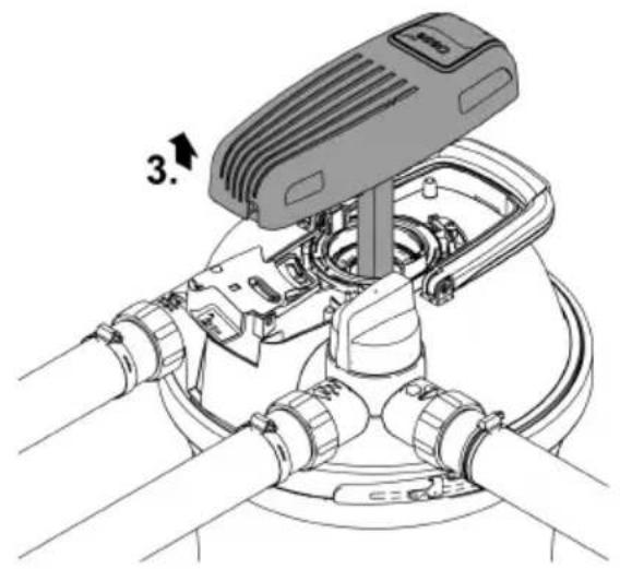
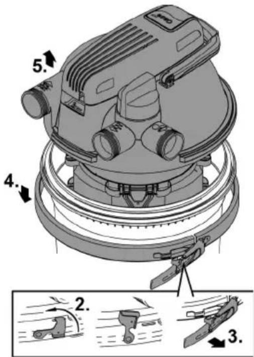
Removing the UVC unit head
How to proceed:
- First pull the power plug of the UVC clarifier before removing the UVC unit head.
- Remove the locking screw, undo the opening ring and remove the UVC unit head.
- If it is not possible to remove the UVC unit head, a vacuum has built up in the quartz glass as a result of the UVC lamp cooling down.
- Remedy: Switch on the UVC clarifier. The heat of the UVC lamp reduces the vacuum and the UVC unit head is pushed up with a plopping sound. Pull the plug of the UVC clarifier and remove the UVC unit head.
FCL0016
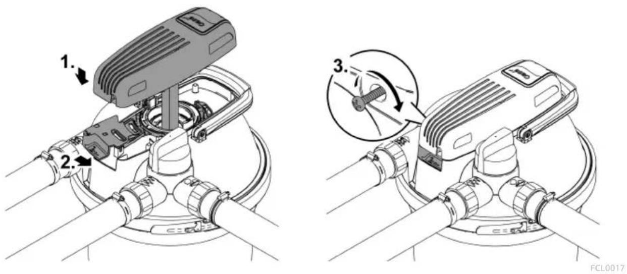
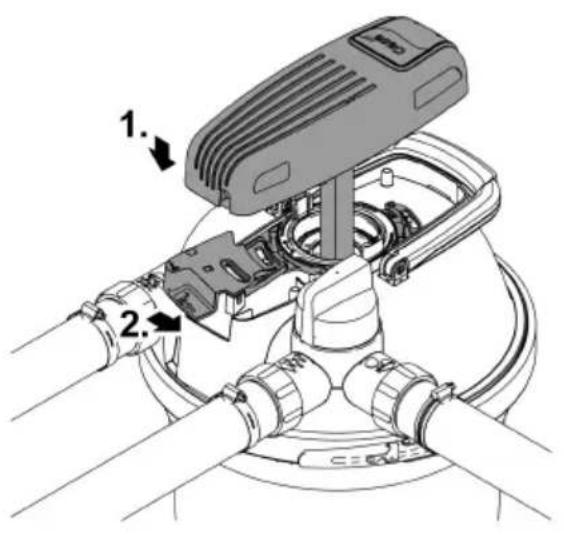
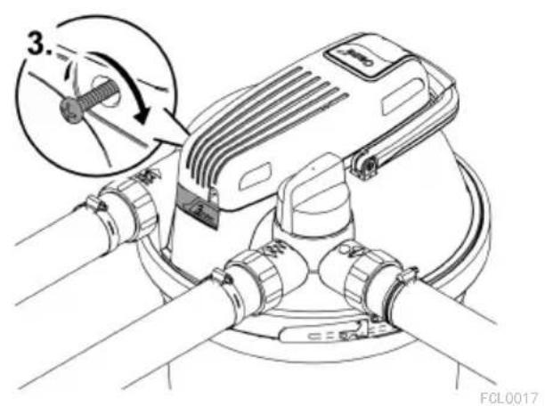
Installing the UVC unit head

Replacing the UVC lamp
The UVC lamp is a wear part. Replace the UVC lamp once the indicated number of operating hours has been reached. This ensures optimum filtering performance.
| FiltoClear | UVC lamp power | Replace UVC lamp after |
| 5000 | 18 W | 8000 h (one pond season) |
| 13000 | 24 W | |
| 19000 | 42 W (optionally 36 W) | 42 W / 60 W: 12000 h |
| 31000 | 60 W (optionally 55 W) | 36 W / 55 W: 8000 h |
Prerequisite:
- The UVC unit head has been removed. (→Removing the UVC unit head)
- Only use UVC lamps, the identification and power data of which correspond to the information on the type plate. (→ Technical data)
How to proceed:
- Removal: Turn the bayonet ring all the way to the "lock open" position to remove the holding plate and the UVC lamp.
- Installation: Turn the bayonet ring all the way to the "lock closed" position. Otherwise you cannot install the UVC unit head.
— On delivery, the bulb of the UVC lamp is protected by a transport guard. The lamp guard is not required for the lamp function and does not need to be reinstalled.
① If necessary remove a lamp guard stuck in the quartz glass as follows:
- Remove the quartz glass. (→ Cleaning/replacing the quartz glass)
— Carefully and steadily knock the rotor lid with the quartz glass against a firm surface. The lamp guard will slowly slide out of the quartz glass.
OSRAM UVC lamps can only be installed without the holding plate. OASE therefore recommends using Philips UVC lamps.
FCL0022
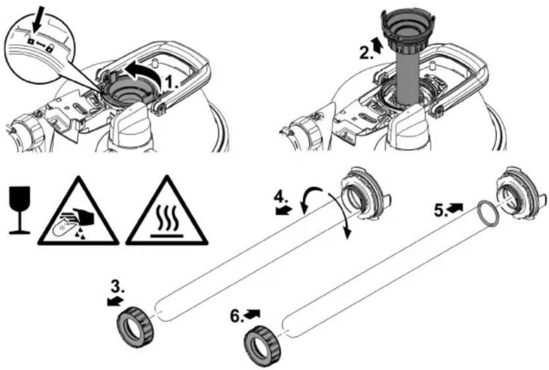
Cleaning/replacing the quartz glass
The quartz glass is fastened in the filter head by a rotor cover so that no water can leak from the container interior.
- Replace the quartz glass if it is scratched or has become opaque. Otherwise the cleaning power of the UVC lamp is no longer sufficient.
CAUTION
The quartz glass and UVC lamp could break and cause cuts.
▶ Act with caution when performing work on the UVC clarifier in order to avoid cuts.
▶ Avoid shocks, impacts and abrupt movements to prevent the glass from breaking.
Prerequisite:
- The UVC unit head has been removed. (→Removing the UVC unit head)
How to proceed:
- Switch off the filter pump.
- Unlock the rotor cover (bayonet lock to "lock open").
- Remove the rotor cover with the quartz glass and, if applicable, the cleaning rotor.
- Turn the turning valve to the dirt water outlet to eliminate any vacuum that may have built up in the container.
- Clean the quartz glass. If you are replacing the quartz glass:
— Undo the clamping screw and carefully pull off the quartz glass with a slight tilting and twisting movement.
- Clean the O-ring, replace it if it is damaged.
- Grease the O-ring with OASE grease (order number 27872) and pull it over the rim of the quartz glass to avoid grease residue on the quartz glass.
- Position the quartz glass on the rotor cover and turn the clamping screw up to the stop, otherwise it is not possible to install the rotor cover.
- Check the profile wear on the cleaning rotor.
- When installing the quartz glass, turn the rotor cover up to the stop (bayonet lock to "lock closed"). Otherwise you cannot install the UVC unit head.
① Condensate may form in the quartz glass. This condensate formation cannot be avoided, however, it does not impair function and safety.
FCL0021
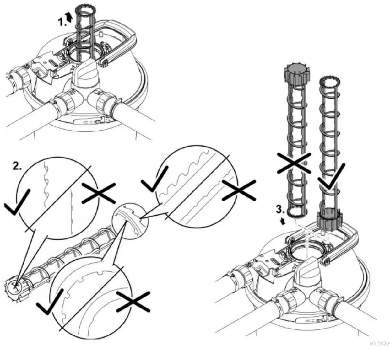
Replacing the cleaning rotor
On the FiltoClear 19000 und FiltoClear 31000, an additional cleaning rotor is positioned above the quartz glass to clean the quartz glass with the aid of the water flow.
- Replace the cleaning rotor when it is worn.
Prerequisite:
- The quartz glass has been removed. (→ Cleaning/replacing the quartz glass)
How to proceed:
- Check the profile wear at both ends and the inner surfaces of the cleaning rotor.
- If the profile is worn, the cleaning rotor will rotate sluggishly and has to be replaced.
- Insert the cleaning rotor in the UVC water housing.
Wear parts
- Foam filters
• UVC lamp, quartz glass and O-ring for quartz glass - Cleaning rotor
- Replacement clamping screw
- Pipe connection FiltoClear 19000, 31000
Decommissioning/winter storage
Shut down the unit at water temperatures below +8 °C or at the latest when freezing temperatures are expected.
- Remove as much water as possible from the containers, the hoses and connections.
- Thoroughly clean all components, check the unit for damage and replace damaged components.
- Store the filter cover, UVC clarifier and filter materials in a dry area protected against freezing.
- Ensure that the storage place is inaccessible to children.
- Cover the container to prevent rain water from entering it.
- Secure the buried container so that it does not pose any risk of accident for persons or animals.
Troubleshooting
| Malfunction | Possible cause | Remedy |
| No water emerges from the water outlet | The filter pump is not switched on | Switch on the filter pump |
| The supply lines are clogged | Check the supply lines and clean them, if necessary | |
| The turning valve is not set to “Filter water” | Turn the turning valve to “Filter water” | |
| The flow rate is too low | The foam filters are clogged | Clean the foam filters |
| The filter pump power is too low | Use a stronger filter pump | |
| The indicator light on the UVC unit head is not lit | The power connection is faulty or the power plug is not plugged in | Check the power connection (power plug, fuse) |
| The temperature switch has turned off the UVC lamp | Allow the UVC lamp to cool down | |
| The UVC lamp is defective | Replace the UVC lamp | |
| The filter capacity is not satisfactory | The turning valve is not set to “Filter water” | Turn the turning valve to “Filter water” |
| The filter has only been used for a short time | Wait a few days/weeks | |
| The water or the pond is extremely soiled | Thoroughly clean the pond | |
| Too many fish and other pond animals | Adhere to the reference value | |
| The foam filters are soiled | Clean the foam filters | |
| The quartz glass is soiled | Clean the quartz glass and the cleaning rotor | |
| The cleaning rotor rotates with difficulty | Check the cleaning rotor for wear and replace, if necessary | |
| The cleaning rotor is not rotating due to soiling | Clean the filterClean the cleaning rotorRemove gravel from the UVC water housing and the foam fil-tersPlace the filter pump at a higher level to prevent it from drawing in coarse dirtUse a pump protection bag (Art. No. 34876) for the filter pump to prevent intake of coarse dirtIf the flow rate is too low, use a stronger filter pump |
The wear limit of the UVC lamp has Replace the UVC lamp been reached (insufficient radiation power)
Technical data
Unit data
| FiltoClear | 5000 | 13000 | 19000 | 31000 | ||
| UVC clarifier | Connection voltage | V AC | 220-240 | 220-240 | 220-240 | 220-240 |
| Mains frequency | Hz | 50/60 | 50/60 | 50/60 | 50/60 | |
| Power consumption | W | 18 | 24 | 42 | 60 | |
| UVC power | W | 18 | 24 | 42 | 60 | |
| UVC lamp | 18 WTC-L(UV-C) | 24 WTCL(UV-C) | 36 W/42 WTC-L(UV-C) | 55 W/60 WTC-L(UV-C) | ||
| Protection type | IP68 | IP68 | IP68 | IP68 | ||
| Max. permissible immersion depth in the water | m | 0.1 | 0.1 | 0.1 | 0.1 | |
| Length of power cable | m | 5 | 5 | 5 | 5 | |
| Min. flow rate | l/h | 2500 | 4500 | 6500 | 8500 | |
| Max. flow rate | l/h | 5000 | 9000 | 13000 | 17000 | |
| Max. permissible pump pressure | bar | 0.6 | 0.6 | 0.6 | 0.6 | |
| Max. permissible operating pressure | bar | 0.2 | 0.2 | 0.2 | 0.2 | |
| Inlet | Connection | G2 | G2 | G2 | G2 | |
| Hose connector | mm | 38, 50 | 38, 50 | 38, 50 | 38, 50 | |
| Outlet | Connection | G2 | G2 | G2 | G2 | |
| Hose connector, transparent | mm | 38, 50 | 38, 50 | 38, 50 | 38, 50 | |
| Dirt outlet | Connection | G2 | G2 | G2 | G2 | |
| Hose connector, transparent | mm | 38, 50 | 38, 50 | 38, 50 | 38, 50 | |
| Number of red foam filters | 1 | 1 | 1 | 2 | ||
| Number of blue foam filters | - | 1 | 2 | 2 | ||
| Number of purple foam filters | 1 | 1 | 1 | 1 | ||
| Suitable for max. pond volume | l | 5000 | 13000 | 19000 | 31000 | |
| Suitable for max. pond volume with fish | l | 2500 | 7000 | 10000 | 15000 | |
| Suitable for max. pond volume with koi | l | - | - | 5000 | 7500 | |
| Permissible ambient temperature during operation | °C | 0 ... +35 | 0 ... +35 | 0 ... +35 | 0 ... +35 | |
| Permissible water temperature | °C | +4 ... +35 | +4 ... +35 | +4 ... +35 | +4 ... +35 | |
| Dimensions | Length | mm | 391 | 391 | 391 | 391 |
| Width | mm | 382 | 382 | 382 | 382 | |
| Height | mm | 370 | 490 | 611 | 732 | |
| Weight | Without water | kg | 8.0 | 8.8 | 9.6 | 10.3 |
| with water | kg | 26 | 36 | 47 | 57 | |
Permissible water values
Fresh water, pond water
| pH value | 6.0 ... 9.0 | |
| Hardness | °dH | 8 ... 15 |
| Free chlorine | mg/l | <0.5 |
| Salt content | % | <0.5 |
| Temperature | °C | +4 ... +35 |
EN
Disposal
NOTE

Do not dispose of this unit with household waste.
▶ Dispose of the UVC lamp and the unit by using the return system provided for this purpose.
▶ Render the unit unusable by cutting the cables.

AVERTISSEMENT
FCL0007
1

natural_image
Technical line drawing of a spray gun with height dimension labeled 'h' (no text or symbols beyond the label)| FiltoClear | Profondeur h |
| 5000 | 0,12 m |
| 13000 | 0,24 m |
| 19000 | 0,36 m |
| 31000 | 0,48 m |
FCL0014
FCL0028
REMARQUE
natural_image
Technical line drawing of a mechanical device with a close-up inset showing internal components (no text or symbols)FR
FCL0015
Exploitation
FCL0018
FCL0019
FCL0023
Nettoyage
natural_image
Technical line drawing of a vacuum cleaner with mesh structure and mechanical components (no text or symbols)FCL0030
FCL0022
FCL0021
Pièces d'usure
FCL0007
1

natural_image
Technical line drawing of a spray gun with height dimension labeled 'h' (no text or symbols beyond the label)| FiltoClear | Ingraafdiepte h |
| 5000 | 0,12 m |
| 13000 | 0,24 m |
| 19000 | 0,36 m |
| 31000 | 0,48 m |
FCL0014
FCL0028
OPMERKING
natural_image
Technical illustration of a mechanical device with a close-up view showing internal components (no text or symbols)FCL0015
Werking
FCL0018
FCL0019
Apparaat schoonmaken en filtersponzen wassen of vervangen

FCL002 ^2
Reinigen
natural_image
Technical illustration of a vacuum cleaner with mesh structure and mechanical components (no text or symbols)NL
FCL0030
FCL0022
FCL0021
Slijtagedelen
FCL0007
1

natural_image
Technical line drawing of a spray gun with height dimension labeled 'h' (no text or symbols beyond the label)FCL0014
FCL0028
INDICACIÓN
natural_image
Technical illustration of a mechanical device with a close-up view showing internal components (no text or symbols)Funcionamiento
FCL0018
Colocar la tapa del filtro

FCL0019

FCL0023
Limpieza
natural_image
Technical line drawing of a vertical cylindrical device mounted on a base, with no visible text or symbols.FCL0030
FCL0022
FCL0021
Piezas de desgaste
FCL0007
1

natural_image
Technical line drawing of a spray gun with height dimension labeled 'h' (no text or symbols beyond the label)| FiltoClear | Profundidade de enterramento h |
| 5000 | 0,12 m |
| 13000 | 0,24 m |
| 19000 | 0,36 m |
| 31000 | 0,48 m |
FCL0014
FCL0028
natural_image
Technical illustration of a mechanical device with a close-up view showing internal components (no text or symbols)FCL0015
Operação

FCL0018

FCL0019

FCL002
Limpar
natural_image
Technical line drawing of a vertical cylindrical device mounted on a base, with no visible text or symbols.PT
FCL0030
Montar o pacote de esponjas

FCL0022
FCL0021
Peças de desgaste
FCL0007
1

natural_image
Technical line drawing of a spray gun with height dimension labeled 'h' (no text or symbols beyond the label)| FiltoClear | Profondità di scavo h |
| 5000 | 0,12 m |
| 13000 | 0,24 m |
| 19000 | 0,36 m |
| 31000 | 0,48 m |
FCL0014
FCL0028
NOTA
natural_image
Technical illustration of a mechanical device with a close-up view showing internal components (no text or symbols)Funzionamento
FCL0018

FCL0019
FCL002
Pulizia
natural_image
Technical line drawing of a vertical cylindrical device mounted on a base, with no visible text or symbols.FCL0030

FCL0022
FCL0021
FCL0007
natural_image
Technical line drawing of a spray gun with height dimension labeled 'h' (no text or symbols beyond the label)| FiltoClear | Nedgravningsdybde h |
| 5000 | 0,12 m |
| 13000 | 0,24 m |
| 19000 | 0,36 m |
| 31000 | 0,48 m |
FCL0014
FCL0028
Ibrugtagning
BEMÆRK
natural_image
Technical illustration of a mechanical device with a close-up view showing internal components (no text or symbols)FCL0015
Drift
FCL0018

FCL0019

FCL0023
Rengøring
natural_image
Technical line drawing of a vertical cylindrical device mounted on a base, with no visible text or symbols.DA
FCL0030
Sæt filtersvampepakken sammen
FCL0021
Lukkedele
- Filterskum
- UVC-pære, kvartsglas og o-ring til kvartsglas
- Rengøringsrotor
- Ekstra klemmeskrue
• Rørtislutning FiltoClear 19000, 31000
Opbevaring/overvintring
Tag systemer ud af drift, när vandtemperaturen er under +8 °C eller senest, när der ventes frost.
FCL0007
1

natural_image
Technical line drawing of a spray gun with height dimension labeled 'h' (no text or symbols beyond the label)| FiltoClear | Nedgravingsdybde / h |
| 5000 | 0,12 m |
| 13000 | 0,24 m |
| 19000 | 0,36 m |
| 31000 | 0,48 m |
FCL0014
FCL0028
Igangsetting
MERK
natural_image
Technical illustration of a mechanical device with a close-up view showing internal components (no text or symbols)FCL0015
NO
Drift
NO
FCL0018
FCL0019
FCL002 ^2
Rengjøring
natural_image
Technical line drawing of a vertical cylindrical device mounted on a base, with no visible text or symbols.FCL0030
Monter sammen filtersvamppakken
FCL0021
Slitedeler
- Skumfilter
- UVC-lampe, kvartsglass og O-ring for kvartsglass
- Renserotor
• Erstatningsklemmeskrue
• Rørtilkobling FiltoClear 19000, 31000
Driftsnedleggelse/overvintring
Apparatet må tas ut av drift ved vanntemperaturer under +8 °C eller senest når det er meldt kulde.
FCL0007
1

natural_image
Technical line drawing of a spray gun with height dimension labeled 'h' (no text or symbols beyond the label)| FiltoClear | Nedgrävningsdjup h |
| 5000 | 0,12 m |
| 13000 | 0,24 m |
| 19000 | 0,36 m |
| 31000 | 0,48 m |
FCL0014
Ansluta smutsutlopp
FCL0028
ANVISNING
natural_image
Technical illustration of a mechanical device with a close-up view showing internal components (no text or symbols)FCL0015
Användning
FCL0018
FCL0019
FCL002
Rengöring
natural_image
Technical line drawing of a vertical cylindrical device mounted on a base, with no visible text or symbols.SV
FCL0030
FCL0022
FCL0021
Byta ut rengöringsrotorn
Slitagedelar
FCL0007
1

natural_image
Technical line drawing of a spray gun with height dimension labeled 'h' (no text or symbols beyond the label)| FiltoClear | Hautaussyvyys h |
| 5000 | 0,12 m |
| 13000 | 0,24 m |
| 19000 | 0,36 m |
| 31000 | 0,48 m |
FCL0014
FCL0028
OHJE
natural_image
Technical illustration of a hairdryer with magnified inset showing internal cable connection (no text or symbols)FCL0015
Käyttö
FI
FCL0018
FCL0019
FCL0023
Puhdistus
natural_image
Technical line drawing of a cylindrical device with mesh structure and internal components (no text or symbols)FCL0030
FCL0021
Kuluvat osat
FCL0007
1

natural_image
Technical line drawing of a spray gun with height dimension labeled 'h' (no text or symbols beyond the label)FCL0014
FCL0028
Üzembe helyezés
TUDNIVALÓ:
natural_image
Technical illustration of a mechanical device with a close-up inset showing internal components (no text or symbols)FCL0015
Üzem
FCL0018
FCL0019

FCL002
Tisztítás
natural_image
Technical line drawing of a vacuum cleaner with mesh structure and mounting base (no text or symbols)HU
FCL0030
FCL0021
Kopóalkatrészek
FCL0007
1

natural_image
Technical line drawing of a spray gun with height dimension labeled 'h' (no text or symbols beyond the label)FCL0014
FCL0028
Rozruch
WSKAZÓWKA
natural_image
Technical illustration of a mechanical device with a close-up view showing internal components (no text or symbols)FCL0015
Eksploatacja
PL
FCL0018

FCL0019
FCL0023
Czyszczenie
natural_image
Technical line drawing of a vacuum cleaner with mesh structure and mounting base (no text or symbols)FCL0030
FCL0021
FCL0007
1

natural_image
Technical line drawing of a spray gun with height dimension labeled 'h' (no text or symbols beyond the label)FCL0028
UPOZORNĚNÍ
natural_image
Technical illustration of a mechanical device with a close-up view showing internal components (no text or symbols)FCL0015
Provoz
FCL0018

CS
FCL0019

FCL0023
Čištění
natural_image
Technical line drawing of a vertical cylindrical device mounted on a base, with no visible text or symbols.FCL0030
CS

Výměna UVC zářivky
FCL0021
FCL0007
1

natural_image
Technical line drawing of a spray gun with height dimension labeled 'h' (no text or symbols beyond the label)| FiltoClear | Híbka zahrabania h |
| 5000 | 0,12 m |
| 13000 | 0,24 m |
| 19000 | 0,36 m |
| 31000 | 0,48 m |
FCL0014
FCL0028
UPOZORNENIE
natural_image
Technical illustration of a mechanical device with a close-up view showing internal components (no text or symbols)FCL0015
Prevádzka
FCL0018
Osadenie veka filtra
FCL0019
Čistenie
natural_image
Technical line drawing of a vacuum cleaner with mesh structure and mounting base (no text or symbols)FCL0030
FCL0021
1

natural_image
Technical line drawing of a spray gun with height dimension labeled 'h' (no text or symbols beyond the label)| FiltoClear | Globina vkopa h |
| 5000 | 0,12 m |
| 13000 | 0,24 m |
| 19000 | 0,36 m |
| 31000 | 0,48 m |
SL
Tlačni filter postavite na ravna tla
Če tlačnega filtra ne zakopljete, ga postavite na manj vidno mesto, npr. skrito za grmovjem.
- Napravo postavite v bližini ribnika.
- Podlaga mora biti trdna in ravna.

FCL0011
Povezovanje odvoda umazanije
FCL0028
NASVET
natural_image
Technical illustration of a mechanical device with a close-up view showing internal components (no text or symbols)FCL0015
Delovanje
FCL0018

FCL0019
FCL0023
Čiščenje
natural_image
Technical line drawing of a vacuum cleaner with mesh structure and internal components (no text or symbols)FCL0030
SL
Sestavljanje paketa filtrirne gobe
FCL0021
Deli, ki se obrabijo
FCL0007
1

natural_image
Technical line drawing of a spray gun with height dimension labeled 'h' (no text or symbols beyond the label)| FiltoClear | Dubine ukapanja h |
| 5000 | 0,12 m |
| 13000 | 0,24 m |
| 19000 | 0,36 m |
| 31000 | 0,48 m |
FCL0014
HR
FCL0028
NAPOMENA
natural_image
Technical illustration of a mechanical device with a close-up view showing internal components (no text or symbols)FCL0015
Rad
FCL0018
HR
Skinuti poklopac filtra

FCL0019
Čišćenje
- Očistite spremnik, obujmicu, poklopac filtra, UVC-spremnik i mrežasto crijevo snažnim vodenim mlazom.
- Mrežasto crijevo možete ukloniti tako što istovremeno vučete i okrećete u smjeru kazaljke na satu.
- Operite spužve filtra snažnim stiskanjem pod tekućom vodom.
— Ako je potrebno, zamijenite spužve filtra.
natural_image
Technical line drawing of a vacuum cleaner with mesh structure and mounting base (no text or symbols)FCL0030
Sastaviti paket spužvica filtra
- Ponovno navucite spužve filtra u predviđenom redoslijedu na mrežastu cijev. (→ Redoslijed ugradnje spužvica filtra)
- Na svaku spužvu filtra stavite jednu odstojnu ploču s po dvije odstojnice.
- Odstojnicu stavite do prianjanja u odstojnu ploču i lagano zakrenite odstojnicu.
- Na sada posljednju spužvu filtra (ljubičasta, 20 ppi) stavite završnu ploču. Završnu ploču pričvrstite s dva vijka na objim šipkama za čišćenje.
- Pritisnite poklopac filtra na spremnik. (→Skinuti poklopac filtra)
FCL0024
Potrošni dijelovi
- Filtarske spužve
- UVC žarulja, kvarcno staklo i O-prsten za kvarcno staklo
- Rotor za čišćenje
- Zamjenski stezni vijak
- Priključak cijevi FiltoClear 19000, 31000
Stavljanje van pogona / prezimljavanje
RO
FCL0007
1

natural_image
Technical line drawing of a spray gun with height dimension labeled 'h' (no text or symbols beyond the label)| FiltoClear | Adâncimea de îngropare h |
| 5000 | 0,12 m |
| 13000 | 0,24 m |
| 19000 | 0,36 m |
| 31000 | 0,48 m |
RO
RO
FCL0014
Racordati evacuarea apei murdare
FCL0028
INDICATIE
natural_image
Technical illustration of a mechanical device with a close-up view showing internal components (no text or symbols)FCL0015
Operare

FCL0018
FCL0019
RO

FCL0023
Curățare
natural_image
Technical line drawing of a vertical cylindrical device mounted on a base, with no visible text or symbols.FCL0030
RO
FCL0016
FCL0022
FCL0021
Consumabile
FCL0007
1

natural_image
Technical line drawing of a spray gun with height dimension labeled 'h' (no text or symbols beyond the label)| FiltoClear | Дълбочина на вкопаване h |
| 5000 | 0,12 m |
| 13000 | 0,24 m |
| 19000 | 0,36 m |
| 31000 | 0,48 m |
FCL0014
FCL0028
УКАЗАНИЕ
natural_image
Technical illustration of a mechanical device with a close-up view showing internal components (no text or symbols)FCL0015
Работа

FCL0018

FCL0019
FCL0023
Почистване
natural_image
Technical line drawing of a vertical cylindrical device mounted on a base, with no visible text or symbols.FCL0030
FCL0016
UVC глава монтиране
Сменете UVC лампата
FCL0022
natural_image
Technical line drawing of a spray gun with height dimension labeled 'h' (no text or symbols beyond the label)UK
FCL0014
FCL0028
ПРИМІТКА
natural_image
Technical illustration of a mechanical device with a close-up view showing internal components (no text or symbols)FCL0015
Експлуатація
natural_image
Technical line drawing of a mechanical device with labeled parts, showing assembly and component details (no text or symbols present)UK
FCL0020
FCL0018

FCL0019
UK
FCL0023
Очищення
natural_image
Technical line drawing of a vertical cylindrical device mounted on a base, with no visible text or symbols.FCL0030
UK
FCL0016

FCL0022
FCL0021
FCL0029
UK
natural_image
Technical line drawing of a spray gun with height dimension labeled 'h' (no text or symbols beyond the label)FCL0014
FCL0028
RU
УКАЗАНИЕ
natural_image
Technical illustration of a mechanical device with a close-up view showing internal components (no text or symbols)FCL0015
Эксплуатация
FCL0020
FCL0018
RU
FCL0019

FCL0023
RU
Чистка
natural_image
Technical line drawing of a vertical cylindrical device mounted on a base, with no visible text or symbols.FCL0030
FCL0016
FCL0022
FCL0029
FCL0007
1

需要清洁的池水进水口
- 接口 G2
2
natural_image
Technical line drawing of a spray gun with height dimension labeled 'h' (no text or symbols beyond the label)| FiltoClear | 埋入深度 h |
| 5000 | 0.12 m |
| 13000 | 0.24 m |
| 19000 | 0.36 m |
| 31000 | 0.48 m |
落地安放压滤器
FCL0014
连接污水出口
FCL0028
提示
natural_image
Technical illustration of a mechanical device with a close-up inset showing internal components (no text or symbols)FCL0015
运行
FCL0020
取下/放上过滤器盖
取下过滤器盖
步骤如下:
FCL0018
放上过滤器盖
FCL0019
清洁设备并清洗或者更换过滤海绵
过滤海绵会因机械应力和正常老化而磨损。
① 在旺季开始时,请插入新过滤海绵。
拆开过滤海绵
前提:

FCL0023
清洁
natural_image
Technical line drawing of a vertical cylindrical device mounted on a base, with no visible text or symbols.FCL0030
ZH
组装过滤海绵
安装 UVC 设备头
更换 UVC 紫外线灯泡
FCL0021
更换清洁转子
磨损件
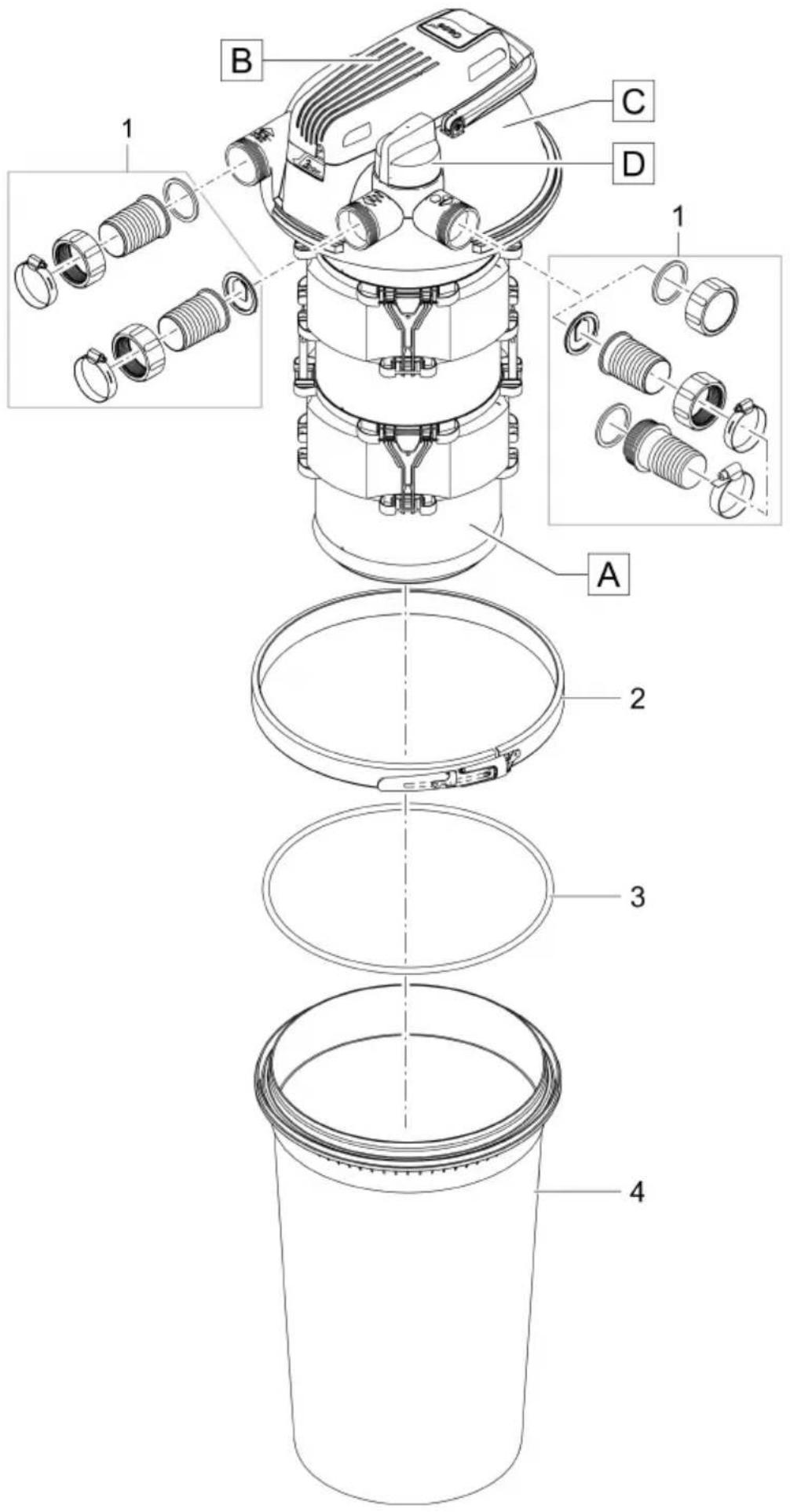
FCL0035
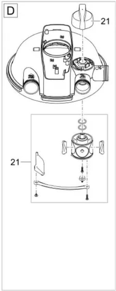
FiltoClear 5000
FiltoClear 13000
| 1 | 83894 | 3 | 77773 | 1 | 83894 | 3 | 77773 |
| 2 | 77754 | 4 | 89001 | 2 | 77754 | 4 | 89002 |
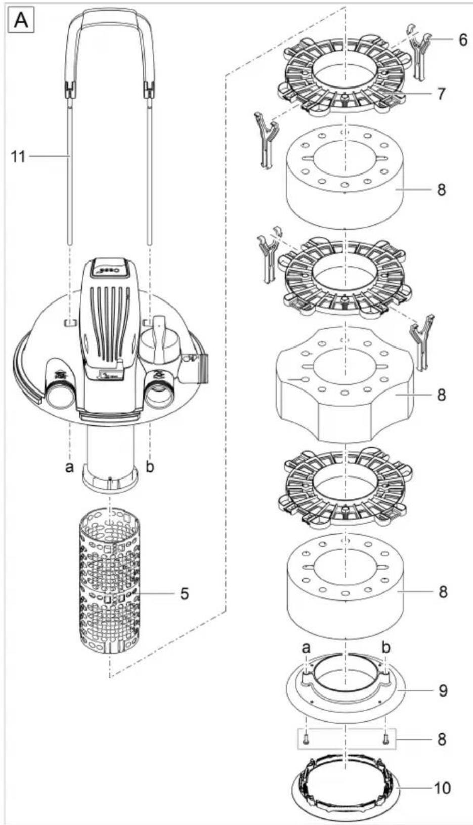
FCL0036
FiltoClear 5000
FiltoClear 13000
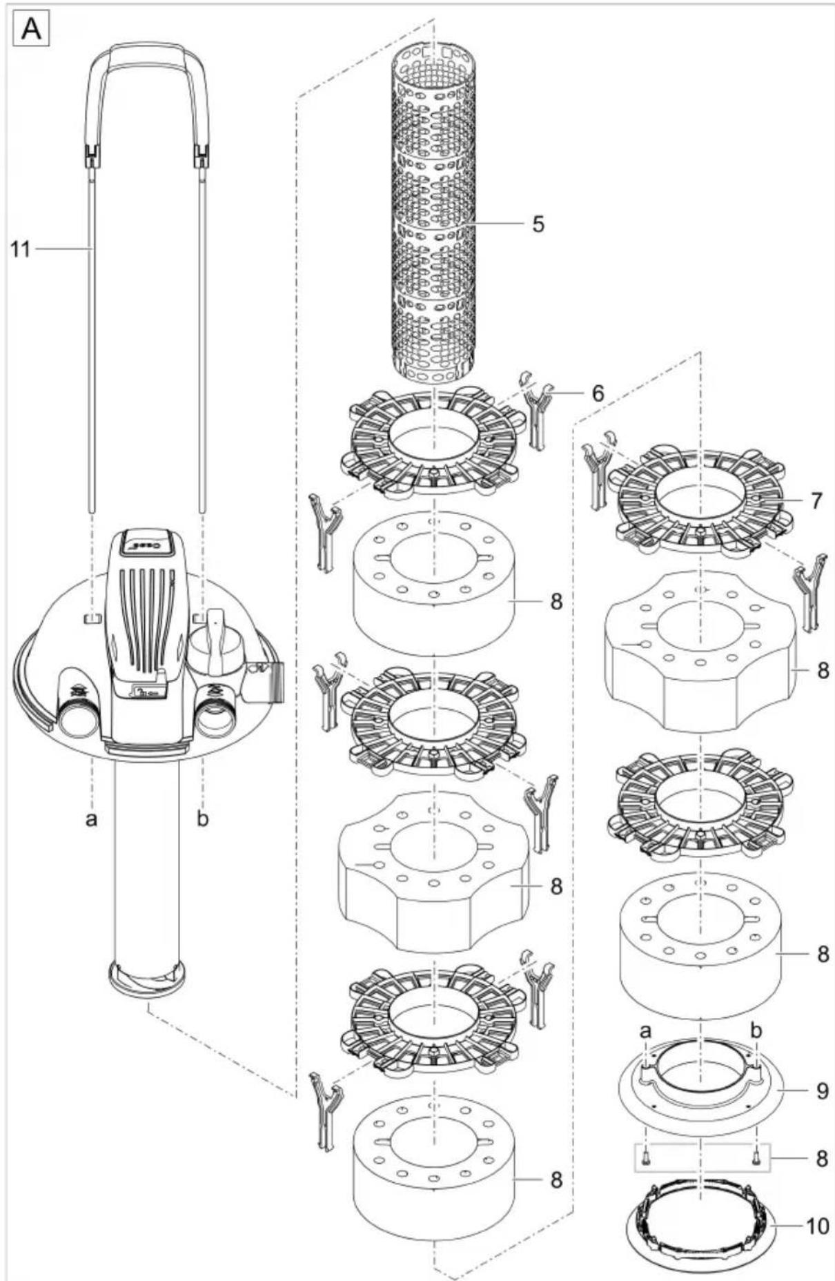
| 5 | 21618 | 8 | 77872 | 5 | 21618 | 8 | 77873 |
| 6 | 77733 | 9 | 77734 | 6 | 77733 | 9 | 77734 |
| 7 | 77732 | 10 | 77735 | 7 | 77732 | 10 | 77735 |
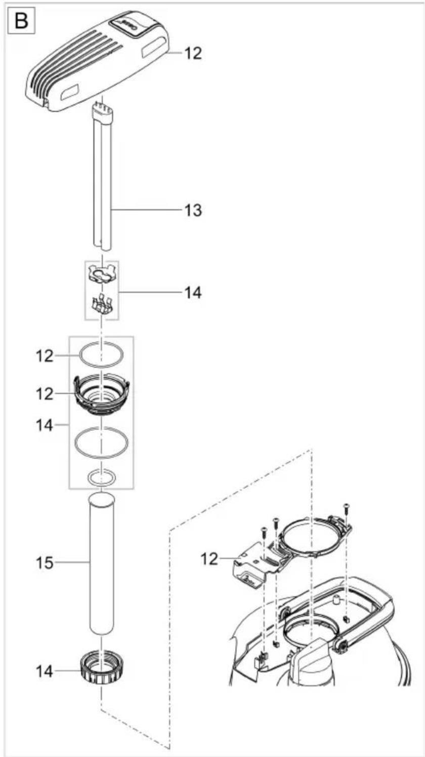
FCL0037
FiltoClear 5000
FiltoClear 13000
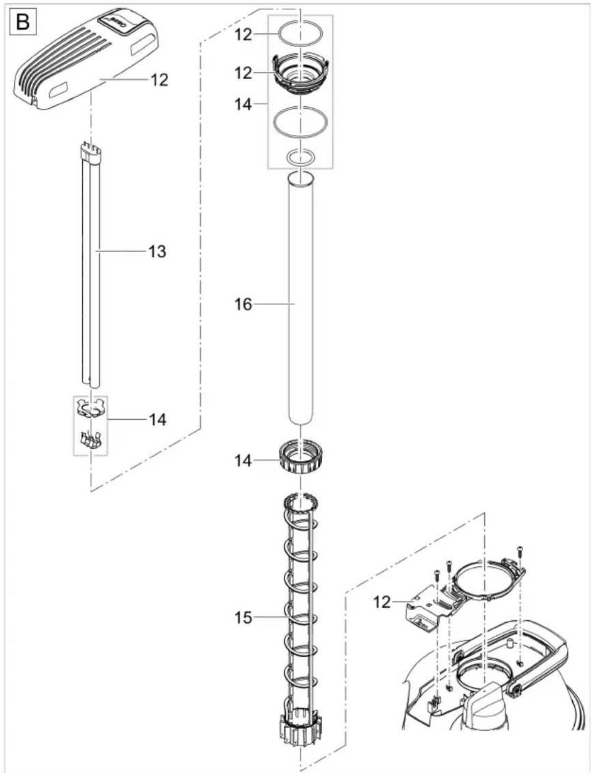
| 12 | 74369 | 14 | 74380 | 12 | 74370 | 14 | 74380 |
| 13 | 56236 | 15 | 74377 | 13 | 56237 | 15 | 13332 |
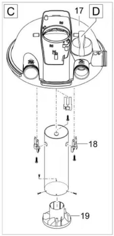
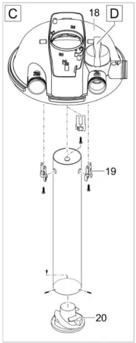
17 74381
18 86941
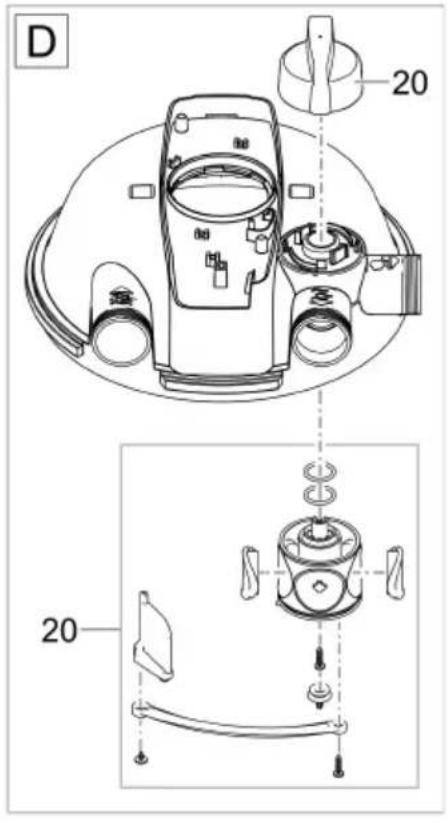
19 15480
20 74368
FCL0042
FCL0031
FiltoClear 19000
FiltoClear 31000
| 1 | 83894 | 3 | 77773 | 1 | 83894 | 3 | 77773 |
| 2 | 77754 | 4 | 89003 | 2 | 77754 | 4 | 89004 |
FCL0032
FiltoClear 19000
FiltoClear 31000
| 5 | 21654 | 9 | 77734 | 5 | 21655 | 9 | 77734 |
| 6 | 77733 | 10 | 77735 | 6 | 77733 | 10 | 77735 |
| 7 | 77732 | 11 | 83890 | 7 | 77732 | 11 | 83891 |
| 8 | 77874 | 8 | 77875 |
FCL0031
FiltoClear 19000
FiltoClear 31000
| 12 | 74371 | 15 | 77748 | 12 | 74372 | 15 | 77749 |
| 13 | 77871 | 16 | 74378 | 13 | 57077 | 16 | 74379 |
| 14 | 74380 | 14 | 74380 |
18 74381
19 86941
20 77750
21 74368
FCL0034
- FiltoClear
- HINWEIS
- Betrieb
- Reinigen
- Verschleißteile
- Safety information
- Electrical connection
- Safe operation
- Intended use
- Product description
- Overview
- Connection components for installation
- Function description
- Cleaning stage "Filtration"
- Cleaning stage "UVC radiation"
- Bypass
- Biological cleaning effect
- Cleaning the foam filters
- Symbols on the unit
- Installation and connection
- Installing the unit
- Burying the pressure filter
- Installing the pressure filter on level ground
- Establishing the connections
- Connecting the inlet
- Connecting the outlet
- Connecting the dirt outlet
- NOTE
- Start-up sequence:
- Switching the UVC clarifier on/off
- Operation
- Maintenance and cleaning
- Removing/positioning the filter cover
- Removing the filter cover
- Positioning the filter cover
- Cleaning the unit and washing or replacing the foam filters
- Disassembling the foam filter package
- Prerequisite:
- Cleaning
- Assembling the foam filter package
- Removing/installing the UVC unit head
- CAUTION
- Removing the UVC unit head
- Installing the UVC unit head
- Replacing the UVC lamp
- How to proceed:
- Cleaning/replacing the quartz glass
- Replacing the cleaning rotor
- Wear parts
- Decommissioning/winter storage
- Technical data
- Unit data
- Permissible water values
- Disposal
- AVERTISSEMENT
- REMARQUE
- Exploitation
- Nettoyage
- Pièces d'usure
- OPMERKING
- Werking
- Apparaat schoonmaken en filtersponzen wassen of vervangen
- Slijtagedelen
- INDICACIÓN
- Funcionamiento
- Colocar la tapa del filtro
- Limpieza
- Piezas de desgaste
- Operação
- Limpar
- Montar o pacote de esponjas
- Peças de desgaste
- NOTA
- Funzionamento
- Pulizia
- Ibrugtagning
- BEMÆRK
- Drift
- Rengøring
- Sæt filtersvampepakken sammen
- Lukkedele
- Opbevaring/overvintring
- Igangsetting
- MERK
- Rengjøring
- Monter sammen filtersvamppakken
- Slitedeler
- Driftsnedleggelse/overvintring
- Ansluta smutsutlopp
- ANVISNING
- Användning
- Rengöring
- Byta ut rengöringsrotorn
- Slitagedelar
- OHJE
- Käyttö
- Puhdistus
- Kuluvat osat
- Üzembe helyezés
- TUDNIVALÓ:
- Üzem
- Tisztítás
- Kopóalkatrészek
- Rozruch
- WSKAZÓWKA
- Eksploatacja
- Czyszczenie
- UPOZORNĚNÍ
- Provoz
- Čištění
- Výměna UVC zářivky
- UPOZORNENIE
- Prevádzka
- Osadenie veka filtra
- Čistenie
- Tlačni filter postavite na ravna tla
- Povezovanje odvoda umazanije
- NASVET
- Delovanje
- Čiščenje
- Sestavljanje paketa filtrirne gobe
- Deli, ki se obrabijo
- NAPOMENA
- Rad
- Skinuti poklopac filtra
- Čišćenje
- Sastaviti paket spužvica filtra
- Potrošni dijelovi
- Stavljanje van pogona / prezimljavanje
- Racordati evacuarea apei murdare
- INDICATIE
- Operare
- Curățare
- Consumabile
- УКАЗАНИЕ
- Работа
- Почистване
- UVC глава монтиране
- Сменете UVC лампата
- ПРИМІТКА
- Експлуатація
- Очищення
- Эксплуатация
- Чистка
- 落地安放压滤器
- 连接污水出口
- 提示
- 运行
- 取下/放上过滤器盖
- 取下过滤器盖
- 放上过滤器盖
- 拆开过滤海绵
- 清洁
- 组装过滤海绵
- 安装 UVC 设备头
- 更换 UVC 紫外线灯泡
- 更换清洁转子
- 磨损件
Brand : OASE
Model : FiltoClear 13000
Category : Water filter