GE 20 - Multitools PROXXON - Free user manual and instructions
Find the device manual for free GE 20 PROXXON in PDF.


User questions about GE 20 PROXXON
0 question about this device. Answer the ones you know or ask your own.
Ask a new question about this device
Download the instructions for your Multitools in PDF format for free! Find your manual GE 20 - PROXXON and take your electronic device back in hand. On this page are published all the documents necessary for the use of your device. GE 20 by PROXXON.
USER MANUAL GE 20 PROXXON
natural_image
Technical line drawing of a mechanical assembly with no visible text or symbolsManual
Deutsch
Fold on the picture pages when reading the user instructions.

9
Français
natural_image
Mechanical linkage diagram with labeled components (no text or symbols)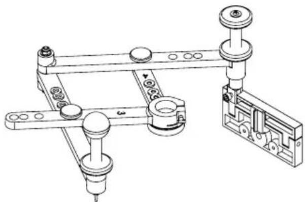
natural_image
Technical line drawing of a mechanical assembly with no visible text or symbolsFig. 5

natural_image
Exploded view of a mechanical component with multiple small black components arranged diagonally (no text or symbols visible)Fig. 6
text_image
Fig. 7a ROXXON-27102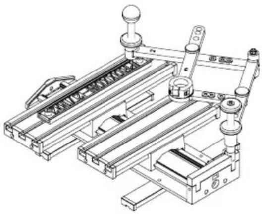
natural_image
Technical line drawing of a mechanical assembly with no visible text or symbolsFig. 7b
natural_image
Technical line drawing of a mechanical assembly with labeled components (no text or symbols beyond label)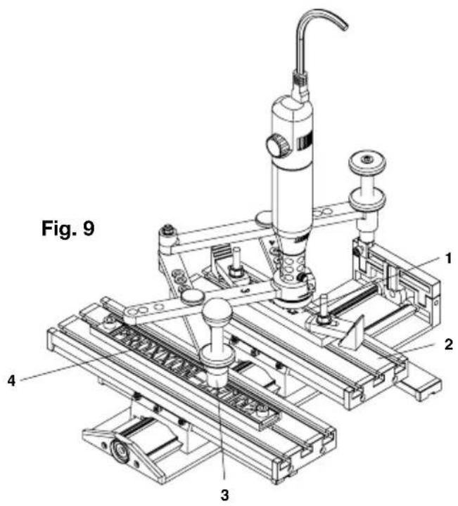
text_image
Fig. 9 1 2 3 4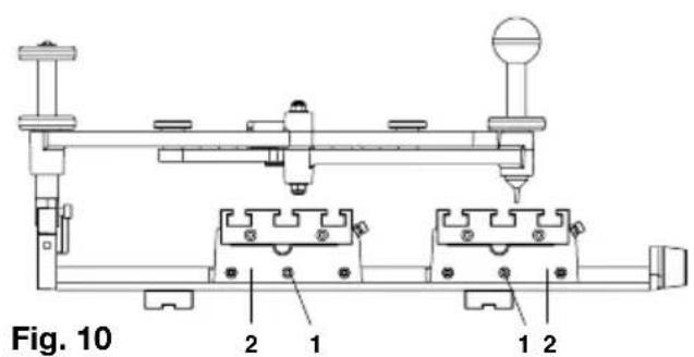
text_image
Fig. 10 2 1 1 2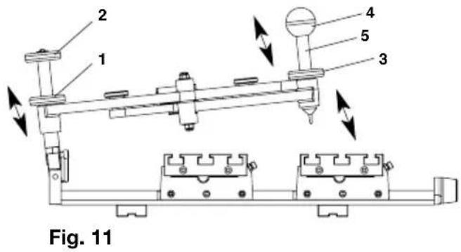
text_image
2 1 4 5 3 Fig. 11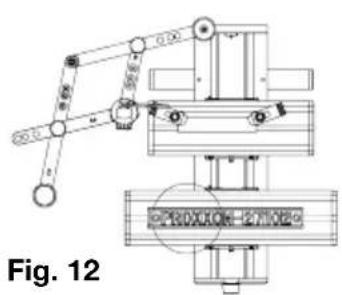
text_image
Fig. 12
text_image
PROXXO ① ② ④ ③
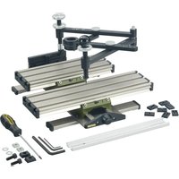
GE 20 engraving device
The GE 20 engraving device is the ideal instrument for engraving ornamentations, letters or numbers on metal or plastic. Signs can therefore be created, small valuables decorated and individual embellishments created on jewellery with ease.
Retailers keep a broad selection of stencils in stock for this purpose, including every conceivable kind of template for plant ornamentation, animals, coats of arms, etc. Stencil templates can, of course, be individually created where a freely invented figure is to be engraved. In this case, no limitations are placed on creativity, and inspiration can be found practically anywhere!
Drawing stencils are provided for creating letters and numbers. These are fixed in position using a guide rail included in the scope of delivery. A maximum of 14 characters can be fitted here adjacent to each other, more than enough for nameplates or similar. The stencils are traced precisely with the guide marker on the GE 20 engraving device which, in turn, is guided with a comfortable ball handle.
This movement is reduced and transmitted to the clamped milling tool. The reduction ratio can be fixed at 2:1, 3:1, 4:1 or 5:1 by simply adjusting two screws.
Our step clamp set (article number 24256) is ideal for clamping and aligning the workpiece to be engraved. This is described in detail in chapter "Accessories" later in this manual.
Further information on useful accessories is also contained in this section. We hope you enjoy working with the engraving device!
Scope of delivery:
- GE 20 engraving device
- Allen key 1.5 mm
- Allen key 3 mm
- Allen key 5 mm
- Screwdriver HX 2.5
- Letter strip
- Letter set
- Fastening set for letter strip
Assembly of the GE 20 engraving device
Fitting the guide marker:
For packaging reasons, the guide marker is not prefitted, but assembly is very simple, as illustrated in Fig. 1:
- Unscrew the ball handle 1 and stop 2 from the guide marker 3
- Screw the guide marker 3 into the threaded hole 4 provided for this purpose
- Screw the ball handle 1 and stop 2 into place again
Fitting the guide arm:
- Insert axle 1 through the opening in the guide arm 2 (see Fig. 2)
- Insert axle 1 together with the guide arm into the hole on the T-slot table 3 intended for this purpose (see illustration). Prior to this, fit the spacer sleeve 4 to the axle 1. Ensure that the axle is turned so that the screw 5 makes contact with the flat position on the underside of the axle!
Selection of reduction ratio
Four reduction ratios can be configured by varying the lever ratios on the guide arm: 2:1 (A), 3:1 (B), 4:1 (C) and 5:1 (D). Only varying combinations of positions of both elements of the guide arm need to be configured for this purpose.
This is really easy. Simply unscrew the knurled screw 1 (Fig. 3), select the desired position for the arms and screw the knurled screw in again.
Note that the arms are labelled with numbers, as shown in the illustration!
We have labelled the respective hole combinations with letters in the illustration which correspond to the details specified above in the text.
For example, Fig. 3 illustrates the configuration for a reduction from 2:1 (i.e. the en-graving is half the size of the original here).
On the other hand, Fig. 4 illustrates an example of a reduction of 5:1.
Positioning the number and letter plates on the guide rails
Push the desired number and letter plates laterally into the guide strip, as illustrated in Fig. 6.
Caution:
Ensure during this that at least 11 number and letter plates are used!
Where surplus plates are required for this purpose, please ensure these are reversed (face down) when pushed into the guide strip!
Please note:
A pressure piece should be inserted at the beginning and end, as shown in the illustration.
Securing the guide rail to the T-slot table
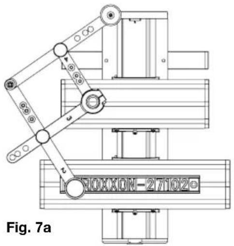
See Fig. 7 a and b: Push the guide strip with the desired letter and number combination and the screws and square nuts included into the centre of the larger of the two tables and screw firmly into position.
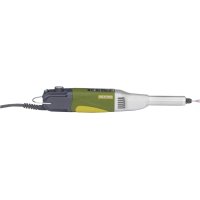
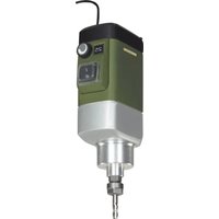
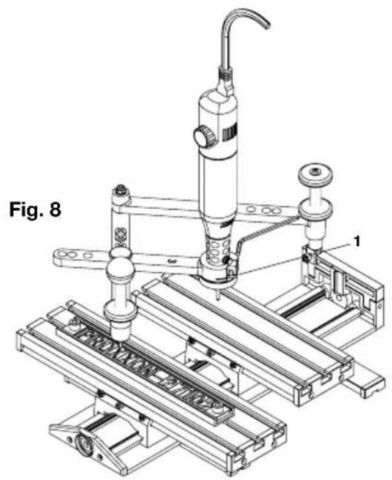
The electric tool can then be clamped into the 20 mm fit. Simply insert as illustrated in Fig. 8 and clamp firmly with the Allen screw 1.
Please do not forget to clamp the tool to be used in the electric tool prior to this!
Attention: The used power tool has to be operated with collets! Using the tree-jaw chuck is not possible.
Align the positions of individual elements and the engraving device settings:
Aligning the guide rail and workpiece (Fig. 9)
Naturally enough, options for movement of the guide arm are limited, depending on the reduction configured. This task is therefore important when it comes to aligning the workpiece position with the working range of the engraving needle.
- Fix the workpiece 1 temporarily to the worktable 2 using appropriate fastening material (e.g. collet set, article no. 24256)
- Then traverse to both end positions of the number and letter sequence 4 to be engraved with the guide marker 3, observing the movements of the engraving needle. Do these
remain in the correct area of the workpiece in every position, and can the needle move freely?
- Please also ensure that the needle does not collide with the fastening media! Following correct aligning, please clamp the workpiece firmly.
Adjustment of the T-slot tables in their guides
This is a further option to align the positions of the workpiece and the stencil with each other if necessary. The procedure is as follows:
- Release the clamping screws 1 (Fig. 10)
- Push one or, if necessary, both tables 2 into the required position
- Retighten the clamping screw 1
Aligning the height setting of the engraving needle and guide marker:
Two options exist for varying the height of the guide arm relative to the workpiece thickness and the engraving needle. Please proceed as follows:
Adjusting the height of the swivel joint:
- Release the locknut 1 (Fig. 11)
- The height can now be adjusted by turning on the handle 2
- Tighten the locknut 1 again when adjustment is completed
Adjusting the height of the guide marker:
- Release the locknut 3.
- The height position can now be adjusted by turning the pin 5 on the handle 4.
- Tighten the locknut 3 again when adjustment is completed.
The guide arm can be raised to a certain degree (see Fig. 11). This is essential when working if the guide marker needs to be moved, but the engraving needle is not engaged.
In addition, improved access to the electric tool when raising facilitates changing the engraving needle.
Engraving
Ensure that all settings are correct. This applies in particular to the guide arm height setting!
- Activate the electric tool
- Insert the guide marker into the slot where the desired number and letter plate is located.
- Engrave the numbers and/or letters.
- Raise the guide arm following completion of a character so that the engraving needle can move freely from engaging into the next letter without colliding with the workpiece.
- Repeat the operation for each number and letter (see Fig. 12). For example, the arm should be raised here following movement 1, movement 2, etc.
Accessories for the GE 20 engraving device
- Solid carbide stylus for use with the GE 70 engraving device
Two needles are available as accessories for our engraving device. Both are excellently suited to the machining of steel, cast steel, non-ferrous metal, plastic, glass, stoneware and tiles. Nose angle 60° for greater stability. Shaft diame-ter 3.2 mm.
Ritz stylus (art. no.: 28764)
For forming thin lines and engraving fine-lined letters. Also for scribing printed circuit boards for later breaking out.
Engraving needle (art. no. 28765)
For V-shaped letters. Letter width 0.5 mm at base.
- Stencil set for GE 70 engraving device (art. no. 27104)
The stencil set delivered with the engraving device is available as an accessory (article number 27104):
It contains the letters A - Z with a hyphen, full stop and dash and the numbers 0 - 9. For use in the GE 20 guide rail.
- Step clamp set, steel (art. no.: 24256)
For securely attaching the objects to be engraved to the engraving device worktable. Complete with two step blocks, two clamps and three threaded bolts with nuts and T-slot nuts. For workpieces up to approx. 18 mm thick. The article is delivered in an elegant wooden box with a sliding lid.

text_image
Exploded view diagram of a mechanical assembly with numbered parts for identificationPROXXON
DE Service-Hinweis
All PROXXON products are thoroughly inspected after production. Should a defect occur nevertheless, please contact the dealer from whom you purchased the product. Only the dealer is responsible for handling all legal warranty claims which refer exclusively to material and manufacturer error.
Improper use, such as capacity overload, damage due to outside influences and normal wear are excluded from the warranty.
You will find further notes regarding "Service and Spare Parts Management" at www.proxxon.com.