
DCD150 - Drill DEWALT - Free user manual and instructions
Find the device manual for free DCD150 DEWALT in PDF.

| Product type | Professional diamond core drill (drill) |
| Brand | DeWalt |
| Model | DCD150 |
| Weight | 5.5 kg (without battery) |
| Power supply | Li-Ion battery (compatible battery packs: DCB546, DCB547/G, DCB548, DCB549) |
| No-load speed (3 speeds) | 0–700 / 0–1350 / 0–2500 rpm |
| Drilling capacity in masonry (handheld mode) | 1st speed: 76–100 mm; 2nd: 38–100 mm; 3rd: 12–38 mm |
| Drilling capacity in wet concrete (handheld mode) | 1st speed: 51–72 mm; 2nd: 38–72 mm; 3rd: 12–38 mm |
| Max. capacity with DCPS151 stand | Up to 162 mm in masonry, 162 mm in wet concrete |
| Arbor thread | Inner: 1/2"; Outer: 1-1/4-7" |
| Max. water pressure | 3 bar |
| Wireless transmitter (Tool Control) | 433 MHz (0.03 mW EIRP) |
| Bluetooth® | 2400 MHz (0.28 mW EIRP) |
| Sound level | Pressure: 97 dB(A); Power: 105 dB(A); Uncertainty K=3 dB(A) |
| Vibrations (wet concrete drilling) | a_t,oo = 6.5 m/s²; K = 1.5 m/s² |
| Anti-rotation system | Overload detection and automatic stop (red/white indicator) |
| Side handle | With integrated water supply, adjustable |
| Package contents | Core drill, side handle, 32mm and 24mm wrenches, 1/2" adapter for dry core bits, storage case, manual |
| Maintenance | Clean with damp cloth and mild soap; no lubrication necessary |
| Safety | Hearing and eye protection mandatory; use auxiliary handle; do not drill overhead |
Frequently Asked Questions - DCD150 DEWALT
User questions about DCD150 DEWALT
0 question about this device. Answer the ones you know or ask your own.
Ask a new question about this device
Download the instructions for your Drill in PDF format for free! Find your manual DCD150 - DEWALT and take your electronic device back in hand. On this page are published all the documents necessary for the use of your device. DCD150 by DEWALT.
USER MANUAL DCD150 DEWALT
English (original instructions) 22
Fig. C2
natural_image
Technical line drawing of a mechanical assembly with no visible text or symbolsFig. C3
natural_image
Technical line drawings of mechanical components, showing front and side views (no text or symbols)Fig. D Fig. E

KERNEBOREMASKINE
DCD150

Director Engineering
Director Engineering
WARNING: Read all safety warnings, instructions, illustrations, and specifications in this manual, including the battery and charger sections provided in an original tool manual or the separate Batteries and Chargers manual. Manuals can be obtained by contacting

Customer Service (refer to the back page of this manual).
Technical Data
| DCD150 | ||
| Type | 1 | |
| No-load speed | ||
| 1st gear | min^-1 | 0-700 |
| 2nd gear | min^-1 | 0-1350 |
| 3rd gear | min^-1 | 0-2500 |
| Inside spindle thread Outside spindle thread | Inside Thread 1/2" Outside Thread: 1-1/4-7" | |
| Dust extraction adaptor thread | 1/2 BSP | |
| Max. water pressure | bar | 3 |
| Minimum underpressure delivered by the vacuum pump | bar | 0.75 |
| Wireless tool control transmitter | ||
| Frequency Band | MHz | 433 |
| Max. Power (EIRP) | mW | 0.03 |
| Bluetooth® Transmitter | ||
| Frequency Band | MHz | 2400 |
| Max. Power (EIRP) | mW | 0.28 |
| Weight | kg | 5.5 |
DRILLING CAPACITIES Diameter
Drilling range in masonry
| 1st gear | |
| Handheld mm | 76–100 |
| Stand mm | 101–162 |
| 2nd gear | |
| Handheld mm | 38–100 |
| Stand mm | 38–101 |
| 3rd gear | |
| Handheld mm | 12–38 |
| Stand mm | 12–38 |
Drilling range in concrete (wet only)
| 1st gear | |
| Handheld mm 51–72 | |
| Stand mm | 76–162 |
| 2nd gear | |
| Handheld mm 38–72 | |
| Stand mm 38–76 | |
| 3rd gear | |
Handheld mm 12–38
Stand mm 12–38
Handheld
| Noise values and vibration values (triax vector sum) according to EN 62841-2-1: | ||
| L_PA (emission sound pressure level) dB(A) 97 | ||
| L_WA (sound power level) dB(A) 105 | ||
| K (uncertainty for the given sound level) | dB(A) 3.0 | |
| Drilling into concrete, wet | ||
| Vibration emission value a_DC = m/s | 2 | 6.5 |
| Uncertainty K = m/s | 2 | 1.5 |
The vibration and/or noise emission level given in this information sheet has been measured in accordance with a standardised test given in EN62841 and may be used to compare one tool with another. It may be used for a preliminary assessment of exposure.
WARNING: The declared vibration and/or noise emission level represents the main applications of the tool. However, if the tool is used for different applications, with different accessories or is poorly maintained, the vibration and/or noise emission may differ. This may significantly increase the exposure level over the total working period. An estimation of the level of exposure to vibration and/or noise should also take into account the times when the tool is switched off or when it is running but not actually doing the job. This may significantly reduce the exposure level over the total working period.
Identify additional safety measures to protect the operator from the effects of vibration and/or noise such as: maintain the tool and the accessories, keep the hands warm (relevant for vibration), organisation of work patterns.
EC-Declaration of Conformity
Machinery Directive and Radio Equipment
Directive

Core Drill
DCD150
DEWALT declares that these products described under "technical data" are in compliance with: 2006/42/EC, EN62841-1:2015 + A11:2022, EN 62841-2-1:2018 + A11:2019 + A12:2022 + A1:2022.
These products also comply with Directive 2011/65/EU and 2014/53/EU.
The full text of the EU declaration of conformity can be requested at the address below or is available at the following internet address: www.2helpu.com (search by the Product and Type Number indicated on the nameplate).
For more information, please contact DEWALT at the following address or refer to the back of the manual.
The undersigned is responsible for compilation of the technical file and makes this declaration on behalf of DEWALT.

Markus Rompel
Director Engineering
65510, Idstein, Germany
31.12.2024

WARNING: To reduce the risk of injury, read the instruction manual.
Definitions: Safety Guidelines
The definitions below describe the level of severity for each signal word. Please read the manual and pay attention to these symbols.
RANGER: Indicates an imminently hazardous situation which, if not avoided, will result in death or serious injury.
WARNING: Indicates a potentially hazardous situation which, if not avoided, could result in death or serious injury.
AUTION: Indicates a potentially hazardous situation which, if not avoided, may result in minor or moderate injury.
NOTICE: Indicates a practice not related to personal injury which, if not avoided, may result in property damage.
▲ denotes risk of electric shock.
Δenotes risk of fire.
GENERAL POWER TOOL SAFETY WARNINGS
WARNING: Read all safety warnings, instructions, illustrations and specifications provided with this power tool. Failure to follow all instructions listed below may result in electric shock, fire and/or serious injury.
SAVE ALL WARNINGS AND INSTRUCTIONS FOR FUTURE REFERENCE
The term "power tool" in the warnings refers to your mains-operated (corded) power tool or battery-operated (cordless) power tool.
1) Work Area Safety
a) Keep work area clean and well lit. Cluttered or dark areas invite accidents.
b) Do not operate power tools in explosive atmospheres, such as in the presence of flammable liquids, gases or dust. Power tools create sparks which may ignite the dust or fumes.
c) Keep children and bystanders away while operating a power tool. Distractions can cause you to lose control.
2) Electrical Safety
a) Power tool plugs must match the outlet. Never modify the plug in any way. Do not use any adapter plugs with earthed (grounded) power tools. Unmodified plugs and matching outlets will reduce risk of electric shock.
b) Avoid body contact with earthed or grounded surfaces, such as pipes, radiators, ranges and refrigerators. There is an increased risk of electric shock if your body is earthed or grounded.
c) Do not expose power tools to rain or wet conditions. Water entering a power tool will increase the risk of electric shock.
d) Do not abuse the cord. Never use the cord for carrying, pulling or unplugging the power tool. Keep cord away from
heat, oil, sharp edges or moving parts. Damaged or entangled cords increase the risk of electric shock.
e) When operating a power tool outdoors, use an extension cord suitable for outdoor use. Use of a cord suitable for outdoor use reduces the risk of electric shock.
f) If operating a power tool in a damp location is unavoidable, use a residual current device (RCD) protected supply. Use of an RCD reduces the risk of electric shock.
3) Personal Safety
a) Stay alert, watch what you are doing and use common sense when operating a power tool. Do not use a power tool while you are tired or under the influence of drugs, alcohol or medication. A moment of inattention while operating power tools may result in serious personal injury.
b) Use personal protective equipment. Always wear eye protection. Protective equipment such as a dust mask, non-skid safety shoes, hard hat or hearing protection used for appropriate conditions will reduce personal injuries.
c) Prevent unintentional starting. Ensure the switch is in the off position before connecting to power source and/or battery pack, picking up or carrying the tool. Carrying power tools with your finger on the switch or energising power tools that have the switch on invites accidents.
d) Remove any adjusting key or wrench before turning the power tool on. A wrench or a key left attached to a rotating part of the power tool may result in personal injury.
e) Do not overreach. Keep proper footing and balance at all times. This enables better control of the power tool in unexpected situations.
f) Dress properly. Do not wear loose clothing or jewellery. Keep your hair and clothing away from moving parts. Loose clothes, jewellery or long hair can be caught in moving parts.
g) If devices are provided for the connection of dust extraction and collection facilities, ensure these are connected and properly used. Use of dust collection can reduce dust-related hazards.
h) Do not let familiarity gained from frequent use of tools allow you to become complacent and ignore tool safety principles. A careless action can cause severe injury within a fraction of a second.
4) Power Tool Use and Care
a) Do not force the power tool. Use the correct power tool for your application. The correct power tool will do the job better and safer at the rate for which it was designed.
b) Do not use the power tool if the switch does not turn it on and off. Any power tool that cannot be controlled with the switch is dangerous and must be repaired.
c) Disconnect the plug from the power source and/or remove the battery pack, if detachable, from the power tool before making any adjustments, changing accessories, or storing power tools. Such preventive safety measures reduce the risk of starting the power tool accidentally.
d) Store idle power tools out of the reach of children and do not allow persons unfamiliar with the power tool or these instructions to operate the power tool. Power tools are dangerous in the hands of untrained users.
e) Maintain power tools and accessories. Check for misalignment or binding of moving parts, breakage of parts and any other condition that may affect the power tool's operation. If damaged, have the power tool repaired before use. Many accidents are caused by poorly maintained power tools.
f) Keep cutting tools sharp and clean. Properly maintained cutting tools with sharp cutting edges are less likely to bind and are easier to control.
g) Use the power tool, accessories and tool bits, etc. in accordance with these instructions, taking into account the working conditions and the work to be performed. Use of the power tool for operations different from those intended could result in a hazardous situation.
h) Keep handles and grasping surfaces dry, clean and free from oil and grease. Slippery handles and grasping surfaces do not allow for safe handling and control of the tool in unexpected situations.
5) Battery Tool Use and Care
a) Recharge only with the charger specified by the manufacturer. A charger that is suitable for one type of battery pack may create a risk of fire when used with another battery pack.
b) Use power tools only with specifically designated battery packs. Use of any other battery packs may create a risk of injury and fire.
c) When battery pack is not in use, keep it away from other metal objects, like paper clips, coins, keys, nails, screws or other small metal objects, that can make a connection from one terminal to another. Shorting the battery terminals together may cause burns or a fire.
d) Under abusive conditions, liquid may be ejected from the battery; avoid contact. If contact accidentally occurs, flush with water. If liquid contacts eyes, additionally seek medical help. Liquid ejected from the battery may cause irritation or burns.
e) Do not use a battery pack or tool that is damaged or modified. Damaged or modified batteries may exhibit unpredictable behaviour resulting in fire, explosion or risk of injury.
f) Do not expose a battery pack or tool to fire or excessive temperature. Exposure to fire or temperature above 130 °C may cause explosion.
g) Follow all charging instructions and do not charge the battery pack or tool outside the temperature range specified in the instructions. Charging improperly or at temperatures outside the specified range may damage the battery and increase the risk of fire.
6) Service
a) Have your power tool serviced by a qualified repair person using only identical replacement parts. This will ensure that the safety of the power tool is maintained.
b) Never service damaged battery packs. Service of battery packs should only be performed by the manufacturer or authorised service providers.
Safety Instructions for All Operations
- Wear ear protectors. Exposure to noise can cause hearing loss.
- Use the auxiliary handle. Loss of control can cause personal injury.
- Brace the tool properly before use. This tool produces a high output torque and without properly bracing the tool during operation, loss of control may occur resulting in personal injury.
- Hold the power tool by insulated gripping surfaces, when performing an operation where the cutting accessory may contact hidden wiring. Cutting accessory contacting a "live" wire may make exposed metal parts of the power tool "live" and could give the operator an electric shock.
Safety Instructions When Using Long Drill Bits
- Never operate at higher speed than the maximum speed rating of the drill bit. At higher speeds, the bit is likely to bend if allowed to rotate freely without contacting the workpiece, resulting in personal injury.
• Always start drilling at low speed and with the bit tip in contact with the workpiece. At higher speeds, the bit is likely to bend if allowed to rotate freely without contacting the workpiece, resulting in personal injury. - Apply pressure only in direct line with the bit and do not apply excessive pressure. Bits can bend causing breakage or loss of control, resulting in personal injury.
Core Drill Safety Warnings
WARNING: This core drill is designed to only be used with the DCPS151 DEWALT POWERSHIFT® Core Drill Stand. Do not use with any other stand. Refer to the DCPS151 DEWALT POWERSHIFT® Core Drill Stand instructions for proper use.
- When performing drilling that requires the use of water, route the water away from the operator's work area or use a liquid collection device. Such precautionary measures keep the operator's work area dry and reduce the risk of electrical shock.
- When the bit is jammed, stop applying downward pressure and turn off the tool. Investigate and take corrective actions to eliminate the cause of the bit jamming.
- When restarting a core drill in the workpiece check that the bit rotates freely before starting. If the bit is jammed, it may not start, may overload the tool, or may cause the core drill to release from the workpiece.
- When drilling through walls or ceilings, ensure to protect persons and the work area on the other side. The bit may extend through the hole or the core may fall out on the other side.
- Drilling is only allowed downward or horizontally. Drilling overhead (upward) drilling, is NOT PERMITTED.
- Wear protective gloves when changing the core bit.
The core bit can become hot if the power tool is operated for a long time.
• Always wait until the power tool has come to a complete stop before setting it down. The application tool may jam and you may lose control of the power tool.
- Ensure that the water-bearing hoses and connecting elements are in perfect condition. Replace aged or worn parts before the next use. Water leaking from parts of the power tool increases the risk of electric shock or destruction of the machine.
- Use suitable detectors to determine whether supply lines are concealed in the work area or contact persons who have the relevant information. Contact with electrical lines can
lead to fire and electric shock. Damage to a gas line can cause an explosion. Penetrating a water pipe can cause property damage or electric shock.
- Hold the power tool firmly with both hands and make sure that you are standing on a stable surface and keep your balance at all times in order to better control the reaction torque. Loss of control can cause personal injury.
- Inspect the core drill before every use. Do not use the core drill if there are any defectives on the trigger switch or any part of the housing. Have the core drill repaired by an authorized repair agent.
- After interrupting the cut, do not switch on until the core bit can rotate freely. A reaction moment that can lead to loss of control can result in injury.
- Mounting the core drill onto the DCPS151 DEWALT POWERSHIFT® Core Drill Stand is recommended to increase the user comfort and is also required with higher diameter core bits to reduce the risk of injuries.
Dry drilling
- Dry drilling is suitable for masonry materials.
• Always use a suitable dust extractor with a suitable dust extractor adaptor attached to the core drill.
• Always use core bits designed for dry drilling. - Do not use the core drill handheld with core bits larger than 100 ~mm .
- Always mount the core drill on a stand when drilling holes larger than 100mm .
- Wear a dust mask when performing dry cuts.
Wet drilling
- Wet drilling is suitable for stone, concrete, and masonry materials.
• Always use a water cooling device, such as a water tank, tap water or a mawal water pump.
• Always use core bits designed for wet drilling. - The maximum water pressure at the water supply fitting is 3 bar. Use a pressure relieve valve in case of a higher water pressure.
- Use only pure tap water for cooling purposes.
- Prevent water from entering the motor or other electrical components.
Residual Risks
In spite of the application of the relevant safety regulations and the implementation of safety devices, certain residual risks cannot be avoided. These are:
- Impairment of hearing.
- Risk of personal injury due to flying particles.
- Risk of burns due to accessories becoming hot during operation.
- Risk of personal injury due to prolonged use.
Package Contents
The package contains:
1 Diamond drilling machine
1 Side handle with integrated water supply
1 Open ended spanner, 32 mm
1 Open ended spanner, 24 mm
1 1/2" adapter for dry corebits
1Kitbox
1 Instructionmanual
- Check for damage to the tool, parts or accessories which may have occurred during transport.
• Take the time to thoroughly read and understand this manual prior to operation.
SAVE THESE INSTRUCTIONS
Battery Type
These battery packs may be used:
| Battery (kg) |
| DCB546 1.08 |
| DCB547/G 1.46 |
| DCB548 1.46 |
| DCB549 2.12 |
Markings on Tool
The following pictograms are shown on the tool:

Read instruction manual before use.

Wear ear protection.

Wear eye protection.
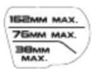
Gear adjustment: The specified maximum core bit diameters are related to the use with a core drill stand wet drilling into concrete. These ratings do not apply to the maximum core bit diameters that can be used in handheld mode.
Date Code Position (Fig. B)
The production date code 21 consists of a 4-digit year followed by a 2-digit week and is extended by a 2-digit factory code.
Description (Fig. A)
WARNING: Never modify the power tool or any part of it.
Damage or personal injury could result.
1 Battery
2 Battery release button
3 Trigger
4 Lock-on button
6 Spindle
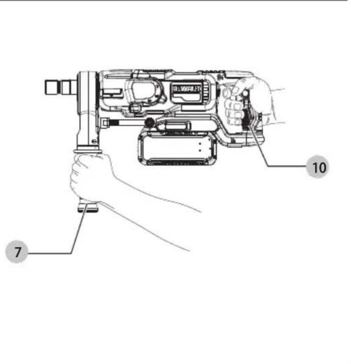
7 Side handle
8 Gear selector
9 Water supply fitting
10 Main handle
5 Heavy load indicator and ANTI-ROTATION LED
Intended Use
Your DCD150 Diamond Core Drill has been designed for dry drilling into masonry materials such as brick, breeze block, etc., with a dry diamond core bit in conjunction with a dust extractor. Your diamond drilling machine can also be used for wet drilling into engineered bricks, stone concrete and reinforced concrete with wet diamond core bits and a water supply.
The machine can be used handheld in applications up to 100 mm for masonry or 72 mm for concrete. When drilling holes larger than 100 mm diameter in masonry or 72 mm diameter in concrete, the core drill must be used on the DCPS151 DEWALT
POWERSHIFT® Core Drill Stand. This tool is not intended to be used for overhead or horizontal drilling upwards with an angle. It is not intended to be used in rain.
DO NOT use under wet conditions or in presence of flammable liquids or gases.
These diamond drills are professional power tools.
DO NOT let children come into contact with the tool.
Supervision is required when inexperienced operators use this tool.
- Young children and the infirm. This appliance is not intended for use by young children or infirm persons without supervision.
- This product is not intended for use by persons (including children) suffering from diminished physical, sensory or mental abilities; lack of experience, knowledge or skills unless they are supervised by a person responsible for their safety. Children should never be left alone with this product.
ANTI-ROTATION System (Fig. A)
Your tool is equipped with the DEWALT ANTI-ROTATION System. This feature senses the motion of the tool and shuts the tool down if excessive. The red heavy load indicator and ANTI-ROTATION LED 5 illuminates when the ANTI-ROTATION System is engaged.
INDICATOR DIAGNOSIS SOLUTION
| OFF Tool is functioning normally | Follow all warnings and instructions when operating the tool. |
| SOLID RED ANTI-ROTATIONSystem has been activated (ENGAGED) | With the tool properly supported, release trigger. The tool will function normally when the trigger is depressed again and the indicator light will go out. |
Electronic Overload Warning (Fig. A)
The heavy load indicator and ANTI-ROTATION LED 5 will illuminate solid white as a warning when the tool is being pushed too hard. When the load is reduced the heavy load indicator and ANTI-ROTATION LED will stop illuminating. Continuing to use the tool after the LED is lit could cause the tool to shut down or reduce run time.
ASSEMBLY AND ADJUSTMENTS
WARNING: To reduce the risk of serious personal injury, turn tool off and disconnect battery pack before making any adjustments or removing/installing attachments or accessories. An accidental start-up can cause injury.
WARNING: Use only DEWALT batteries and chargers.
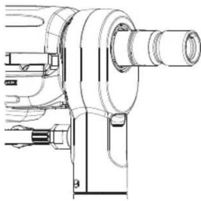
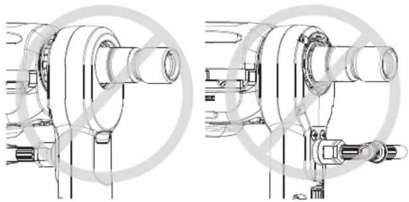
Fitting the Side Handle (Fig. C1–C3)
WARNING: To reduce the risk of personal injury, ALWAYS operate the tool with the side handle properly installed. Failure to do so may result in the side handle slipping during tool operation and subsequent loss of control. Hold tool with both hands to maximize control. The side handle 7 clamps to the front of the gear case and may be installed in multiple positions to permit right- or left-hand use.
-
Orient the side handle with the water supply fitting 9 facing towards the gear case.
-
After the side handle is rotated into position, it should be pushed rearward until the slots 11 on the lip of the side handle are aligned and fully engaged with the projecting tabs 12 of the gear case.
- The side handle is then securely clamped by turning the handle grip 13 clockwise until tight.
Be sure to grip the side handle at the far end on the handle grip to control the tool during a stall.
IMPORTANT: Figure C2 illustrates the correct installation and Figure C3 illustrates two different incorrect installations of the side handle.
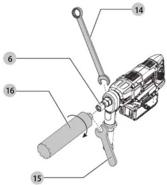
Mounting and Removing a Core Bit to the Core Drill (Fig. D)
This tool uses threaded core bits and adaptors which thread directly onto the spindle 6 of the core drill.
- Choose the appropriate core bit for wet or dry drilling.
- Follow the core bit manufacturer's recommendations for mounting the accessory. For some smaller core bit sizes, you will require an 1/2 BSP to 1/2 BSP (female to female) adaptor to fit the bit onto the spindle. This adaptor is included with the DEWALT POWERSHIFT® DCD150 Core Drill Kit.
- Hold the spindle using the supplied 32 mm wrench 14 and tighten the core bit 16 by rotating anticlockwise, looking toward the drilling hole, using a customer supplied wrench 15.
- To remove the core bit, hold the spindle using the supplied 32 mm wrench and loosen the core bit by rotating clockwise, looking toward the drilling hole, using a customer supplied wrench.
WARNING: Make sure the entire assembly is tight before starting the operation.
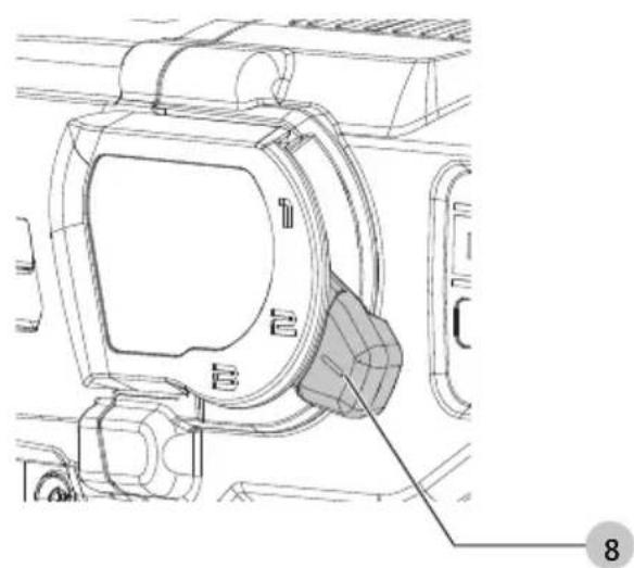
Gear Selector (Fig. E)
The tool is fitted with a gear selector 8 to vary the speed/torque ratio.
- Release the switch and select the required position after the motor has come to a complete standstill.
- Always align the selector with the marks on the gear housing.
- Refer to the Technical Data to choose the appropriate speed according to the diameter of the core bit and the material to be drilled.
- Do not change speed at full speed or during use.
Connecting to a Water Supply (Fig. F)
The water supply fitting 9 on this tool connects to a water supply using quick-connect.
- To connect the quick-connect hose to the water supply fitting 9 place the end of the quick-connect hose onto the fitting.
- Close the water tap 18 by rotating fully to the left.
- Connect an appropriate water supply system to the adaptor. The DCE6820 DEWALT 18V XR Water Tank is the recommended water supply system.
- Start water flow by rotating the water tap 18 to the right and adjust to the necessary flow rate.
- To remove the quick-connect hose, pull back on the quick-connect collar 19 and remove the hose from the fitting.
WARNING: Make sure that the pressure of the water supply is below the max. pressure as stated in Technical Data.
Regulating the Water Flow (Fig. F)
The water tap 18 on the side handle can be adjusted to regulate the flow of cooling water towards the drill bit.
- To reduce the flow, push the valve to the left.
- To increase the flow, push the valve to the right.
Prior to Operation
- Attach the appropriate accessory.
- Mark the spot where the hole is to be drilled.
OPERATION
Instructions for Use
WARNING: Always observe the safety instructions and applicable regulations.
WARNING: To reduce the risk of serious personal injury, turn tool off and disconnect battery pack before making any adjustments or removing/installing attachments or accessories. An accidental start-up can cause injury.
Instructions for Use
WARNING:
- Be aware of the location of pipework and wiring.
- Keep the core bit perpendicular to the surface to be drilled.
- Apply only a gentle pressure to the tool. Excessive force does not speed up drilling but decreases tool performance and may shorten tool life.
Proper Hand Position (Fig. G)
WARNING: To reduce the risk of serious personal injury, ALWAYS use proper hand position as shown.
WARNING: To reduce the risk of serious personal injury, ALWAYS hold securely in anticipation of a sudden reaction. Proper hand position requires one hand on the side handle 7, with the other hand on the main handle 10.
Installing and Removing the Battery Pack (Fig. B)
WARNING: Ensure the tool/appliance is in the off position before inserting the battery pack.
nOTE: For best results, make sure your battery pack is fully charged.
- To install the battery pack 1 into the tool handle, align the battery pack with the rails inside the tool's handle and slide it into the handle until the battery pack is firmly seated in the tool and ensure that it does not disengage.
- To remove the battery pack from the tool, press the battery pack release button 2 and firmly pull the battery pack out of the tool handle. Insert it into the charger.
Fuel Gauge Battery Packs (Fig. B)
DEWALT battery packs include a fuel gauge, which consists of three green LED lights that indicate the level of charge remaining in the battery pack.
To actuate the fuel gauge, press and hold the fuel gauge button 20. A combination of the three green LED lights will illuminate, designating the level of charge left. When the level of charge in the battery is below the usable limit, the fuel gauge will not illuminate and the battery will need to be recharged.
NOTE: The fuel gauge is only an indication of the charge left on the battery pack. It does not indicate tool functionality and is subject to variation based on product components, temperature and end-user application.
Switching On and Off (Fig. A)
WARNING: DO NOT lock the switch ON during handheld use. Continuous operation only when operated on the DCPS151 DEWALT POWERSHIFT® Core Drill Stand. To run the tool, press the variable speed switch 3. The pressure exerted on the variable speed switch determines the tool speed. To stop the tool, release the switch.
For continuous operation, while the drill is mounted in the stand, press and hold down the switch, press the lock-on button 4 and release the switch.
To stop the tool in continuous operation, press the switch briefly and release it. Always switch off the tool when work is finished.
Wireless Tool Control™ (Fig. A)
AUTION: Read all safety warnings, instructions and specifications of the appliance which is paired with the tool. Your tool is equipped with a Wireless Tool Control™ transmitter which allows your tool to be wirelessly paired with another Wireless Tool Control™ device, such as the DCE6820 DEWALT 18V XR Water tank or dust extractor.
To pair your tool using Wireless Tool Control™, depress the trigger switch 3 and the Wireless Tool Control™ pairing button on the separate device. An LED on the separate device will let you know when your tool has been successfully paired.
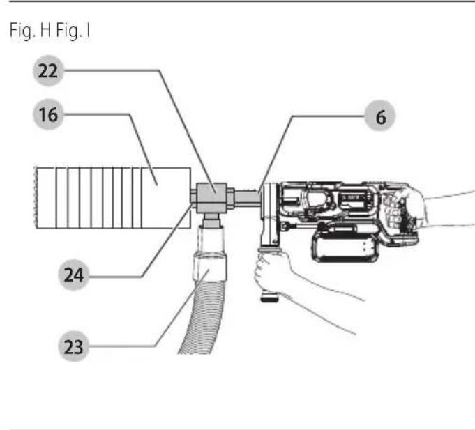
Dust Extraction (Fig. H)
- Attach the dust extraction adaptor 22 with a suitable thread to the spindle 6 of the core drill.
- Attach the dust extraction hose 23 to the dust extraction port on the dust extraction adaptor, using a suitable hose geometry to fit to the dust extraction adaptor used.
- Attach the core bit 16 to the output shaft 24 of the dust extraction adaptor.
General Tips for Drilling with Diamond Core Bits
WARNING: Follow the core bit manufacturer's recommendations for using the accessory.
WARNING: When using the core drill in handheld applications, a centering bit is necessary while starting the hole to reduce the risk of loss of tool control and to control the location of the hole to be drilled more accurately. When using the core drill in stationary applications, i.e., on the DCPS151 DEWALT POWERSHIFT® Core Drill Stand, the use of a centering bit is not necessary.
To install the recommended centering bit:
- Assemble the centering bit into the core bit.
The centering bit is mounted into an adaptor fitted between the spindle of the core drill and the core bit. - Place the centering bit on the center point of the intended hole and switch on the core drill.
- Drill at low speed until the core penetrates the surface approx. 5-10 mm.
- Remove the core drill from the hole and remove the battery.
- Remove the centering bit from its holder.
- Reinstall the battery and insert the core bit into the workpiece.
- Continue drilling, increasing to full speed and drill to the desired depth.
Wet Drilling
- Connect the core drill to an appropriate water supply system, such as the recommended DCE6820 DEWALT 18V XR Water tank.
- Adjust the water flow as necessary.
- Proceed as described above.
WARNING: If any water comes out of the drainage hole at the gear neck, stop the work immediately and have the machine repaired by an authorized repair agent.
Drilling with a Stand
This core drill is designed to only be used with the DCPS151 DEWALT POWERSHIFT® Core Drill Stand. Do not use with any other stand.
MAINTENANCE
Your power tool has been designed to operate over a long period of time with a minimum of maintenance. Continuous satisfactory operation depends upon proper tool care and regular cleaning.
WARNING: To reduce the risk of serious personal injury, turn tool off and disconnect battery pack before making any adjustments or removing/installing attachments or accessories. An accidental start-up can cause injury. The charger and battery pack are not serviceable.
Transport
AUTION: Accidental startup during transport!
• Always transport your core drill with the battery removed.
- Check the core drill for damage before use after transporting.
Storage
- Before storage, remove the battery from the core drill.
- Clean the core drill before storage. Refer to Cleaning.
- Store the core drill in a cool and dry place.
- Store the core drill in a place where they cannot be accessed by children or unauthorised persons.
- Check the core drill for damage before use after long periods of storage.
Lubrication
Your power tool requires no additional lubrication.
Cleaning
WARNING: Electrical shock and mechanical hazard. Remove the battery before cleaning.
WARNING: To ensure safe and efficient operation, always keep the electrical appliance and the ventilation slots clean.
WARNING: Never use solvents or other harsh chemicals for cleaning the non-metallic parts of the tool. These chemicals may weaken the materials used in these parts. Use a cloth dampened only with water and mild soap. Never let any liquid get inside the tool; never immerse any part of the tool into a liquid. Ventilation slots can be cleaned using a dry, soft non-metallic brush and/or a suitable vacuum cleaner. Do not use water or any cleaning solutions. Wear approved eye protection and an approved dust mask.
Optional Accessories
WARNING: Since accessories, other than those offered by DEWALT, have not been tested with this product, use of such accessories with this tool could be hazardous. To reduce the risk of injury, only DEWALT-recommended accessories should be used with this product.
Consult your dealer for further information on the appropriate accessories.
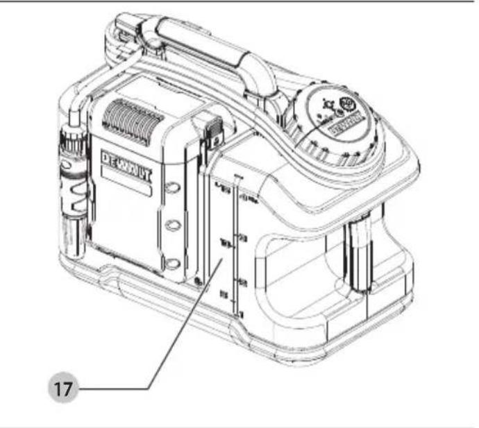
Water Tank (Fig. I)
Optional Accessory
Removing debris from the working area and cooling the core bit in wet applications, the DCE6820 DEWALT 18V XR Water tank 17 ensures water supply where main water supply is not available.
Drill Stand
Optional Accessory
The DCPS151 DEWALT POWERSHIFT® Core Drill Stand allows your core drill to be used in stand applications for increased accuracy, comfort and stability. This core drill is designed to be used handheld or with the DCPS151 DEWALT POWERSHIFT® Core Drill Stand. Do not use with any other drill supporting device. Refer to the DCPS151 DEWALT POWERSHIFT® Core Drill Stand instructions for proper use.
Protecting the Environment


Products/batteries are recyclable, but if marked with the crossed-out bin, they must not be disposed of with normal household waste.
Run the batteries down completely and separate them, and separate any light sources from the product if possible. It is the user's responsibility to delete personal data from the product. Then take the waste to an official waste collection center or a participating retailer who will often accept it free of charge. Packaging should be discarded based on the marked material code. Operating and safety instructions should only be discarded once the applicable product is no longer in use. Please check with your local community/municipality for waste management guidance. For further information, visit www.2helpU.com and scan the above QR code.
Troubleshooting
If your core drill seems not to operate properly, follow the instructions below. If this does not solve the problem, please contact your repair agent.
| Problem Probable cause Solution | ||
| Core bit does not cut Material too hard for core bit. Segments and core are burnt. | Choose a more appropriate core bit (with softer segments). | |
| Apply wet drilling when appropriate. Release pressure. | ||
| Segments look glazed and polished. Drill in abrasive material to re-expose diamond segments. | ||
| Evacuated water too clear and too fluid | Water flow slows down the cutting action and prevents the diamond segments to self-sharpen. | Reduce water flow. |
| Dust accumulating in core bit Accumulating dust slows down the drilling speed. | Use the appropriate dust extraction device. | |
| Disengage drill bit regularly to evacuate cuttings. | ||
| Rotating speed not appropriate Speed rating is not set to the correct option. | Refer to Technical Data for proper speed ratings. | |
| Segments wear too fast Choose a more appropriate core bit | (with harder segments). | |
| Reduce the pressure applied on the core bit. | ||
| Core bit stuck in handheld use 1. Remove the battery from the drill. | 2. Use wrenches to release the spindle from the core bit.3. Turn the spindle as long as it is disconnected from the core bit.4. Place the core drill and the battery in a secure dry place.5. Remove the core bit from hole. | |
| Water leaks at the connection point during operation | Quick connection point is not completely secured. Quick connection point is damaged/ cracked. | 1. Remove the battery from the drill.2. Disconnect the quick connector from the water hose.3. Check the quick connector for any damages.4. Insert the quick connection back onto the hose, ensuring it is fully seated to the connection point. |
Problem Probable cause Solution
| No water is flowing The flow of water is blocked.The water source is empty or hindered. | 1. Stop drilling.2. Close the water valve.3. Close the water supply source.4. Disconnect the battery and store it safely.5. Disconnect the drill from the stand and check if the water inlet hole is not clogged on the drill side.NOTE: Do not use any tool if it is clogged. To unclog it, take the core drill to an authorised DEWALT service center.6. If the water inlet of hole is open, store the unit in the kitbox.7. Connect the water hose, turn on the water source. Check if the water is flowing, if not:a. Check stand mounted hose for leakage.8. If no water is flowing, the water lines are clogged take the core drill to an authorised DEWALT service center.9. If there is leaking other than on the outlet, take the core drill to an authorised DEWALT service center. |
Speed of drilling progress slows Maximum drilling depth was
| been achieved. | |
| Contact pressure insufficient. Increase contact pressure. | |
| Damaged or defective core bit. Visually inspect the core bit. If there are signs of damage, discard the core bit and replace with a new core bit. | |
| The flow of water is too fast. Reduce the flow of water by pushing the water flow valve to the left. | |
| The flow of water is too slow. Increase the flow of water by pushing the water flow valve to the right. | |
| Excessive dust impeding the progress. Connect an appropriate dust extractor to remove dust from the area. | |
| Core bit is polished. Use a sharpening plate to sharpen the core bit. | |
| The core is stuck in the core bit. Remove the core from the core bit. |
TALADRO SACANÚCLEOS
DCD150

Director Engineering
BEWAAR ALLE WAARSCHUWINGEN EN INSTRUCTIES ALS TOEKOMSTIG REFERENTIEMATERIAAL
INDICATOR DIAGNOSE OPLOSSING
Director Engineering
Director de Engenharia
MERKKIVALO VIANMÄÄRITYS RATKAISU
Director Engineering