
GRIND - Keyboard BEHRINGER - Free user manual and instructions
Find the device manual for free GRIND BEHRINGER in PDF.

| Product Type | Analog synthesizer with 13-note capacitive keyboard |
| Brand | Behringer |
| Model | GRIND |
| Power Supply | 12 V DC power adapter (included), 100-240 V, 50/60 Hz |
| Oscillator (VCO) | VCO with FM modulation, Morph, Timbre, Harmonics; range 8 octaves or 14 semitones |
| Filter (VCF) | Low-pass, high-pass, LPG (24 dB/octave) with resonance and modulation |
| Envelope | ADSR (Attack, Decay, Sustain) |
| LFO | Variable frequency, square and triangle waveforms |
| Sequencer | 32 steps, 8 patterns, 8 banks, step-by-step or keyboard; live editing |
| Arpeggiator | 8 modes (Up, Down, Random, etc.) with hold |
| Polyphony | Monophonic |
| MIDI Connectivity | DIN 5-pin In/Out/Thru, USB MIDI class-compliant |
| Audio Connectors | VCA/Line output (3.5 mm TS), headphone output (3.5 mm TRS) |
| CV Patchbay | 16 CV inputs/outputs (3.5 mm TS): VCO, VCF, Envelope, LFO, Mix, etc. |
| Keyboard | 13 capacitive keys with octave operation (LED) |
| Maintenance and Cleaning | Clean with a dry cloth. Do not use solvents. |
| Safety | Do not open the device; do not expose to water or moisture; use only the supplied adapter. |
| Spare Parts and Repairability | No user-serviceable parts. Refer all servicing to qualified personnel. |
| Warranty | Limited warranty – see musictribe.com/support |
| Firmware Update | Via the SynthTribe app (free download at behringer.com) |
Frequently Asked Questions - GRIND BEHRINGER
User questions about GRIND BEHRINGER
0 question about this device. Answer the ones you know or ask your own.
Ask a new question about this device
Download the instructions for your Keyboard in PDF format for free! Find your manual GRIND - BEHRINGER and take your electronic device back in hand. On this page are published all the documents necessary for the use of your device. GRIND by BEHRINGER.
USER MANUAL GRIND BEHRINGER
Hybrid Semi-Modular Synthesizer with 24 Digital Sound Engines, Analog Ladder Filter, 32-Step Sequencer and 16-Voice Poly Chain
23QuGARNEdart Guide
EN
ES
Important Safety Instructions
Terminals marked with this symbol carry electrical current of sufficient magnitude to constitute risk of electric shock. Use only high-quality professional speaker cables with 14 " TS or twist-locking plugs pre-installed. All other installation or modification should be performed only by qualified personnel.
This symbol, wherever it appears, alerts you to the presence of uninsulated dangerous voltage inside the enclosure - voltage that may be sufficient to constitute a risk of shock.
This symbol, wherever it appears, alerts you to important operating and maintenance instructions in the accompanying literature. Please read the manual.
Caution To reduce the risk of electric shock, do not remove the top cover (or the rear section). No user serviceable parts inside. Refer servicing to qualified personnel.
Caution To reduce the risk of fire or electric shock, do not expose this appliance to rain and moisture. The apparatus shall not be exposed to dripping or splashing liquids and no objects filled with liquids, such as vases, shall be placed on the apparatus.
Caution These service instructions are for use by qualified service personnel only. To reduce the risk of electric shock do not perform any servicing other than that contained in the operation instructions. Repairs have to be performed by qualified service personnel.
Warning Please refer to the information on the exterior of bottom enclosure for electrical and safety information before installing or operating the device.
- Please read and follow all instructions and warnings.
- Keep the apparatus away from water (except for outdoor products).
- Clean only with dry cloth.
-
Do not block ventilation openings. Do not install in a confined space. Install only according to manufacturer's instructions.
-
Protect the power cord from damage, particularly at plugs and appliance socket.
-
Do not install near any heat sources such as radiators, heat registers, stoves or other apparatus (including amplifiers) that produce heat.
-
Do not defeat the safety purpose of the polarized or grounding-type plug. A polarized plug has two blades with one wider than the other (only for USA and Canada). A grounding-type plug has two blades and a third grounding prong. The wide blade or the third prong are provided for your safety. If the provided plug does not fit into your outlet, consult an electrician for replacement of the obsolete outlet.
-
Use only attachments and accessories recommended by the manufacturer.

9. Use only specified carts, stands, tripods,
brackets, or tables. Use caution to prevent tip-over when moving the cart/apparatus combination.
-
Unplug during storms, or if not in use for a long period.
-
Only use qualified personnel for servicing, especially after damage.
-
The apparatus with protective earthing terminal shall be connected to a MAINS socket outlet with a protective earthing connection.
- Where the MAINS plug or an appliance coupler is used as the disconnect device, the disconnect device shall remain readily operable.
- Avoid installing in confined spaces like bookcases.
- Do not place naked flame sources, such as lighted candles, on the apparatus.
- Operating temperature range 5° to 45°C (41° to 113°F).
LEGAL DISCLAIMER
Music Tribe accepts no liability for any loss which may be suffered by any person who relies either wholly or in part upon any description, photograph, or statement contained herein. Technical specifications, appearances and other information are subject to change without notice. All trademarks are the property of their respective owners. Midas, Klark Teknik, Lab Gruppen, Lake, Tannoy, Turbosound, TC Electronic, TC Helicon, Behringer, Bugera, Aston Microphones
and Coolaudio are trademarks or registered trademarks of Music Tribe Global Brands Ltd. © Music Tribe Global Brands Ltd. 2024 All rights reserved.
LIMITED WARRANTY
For the applicable warranty terms and conditions and additional information regarding Music Tribe's Limited Warranty, please see complete details online at community.musictribe.com/support.
BESCHRÄNKTE GARANTIE
PASQUE D'AVELIE TINNOLUE

感電の.恐れがありますの
flowchart
graph TD
    A["43"] --> B["1"]
    C["44"] --> D["3"]
    E["45"] --> F["6"]
    G["46"] --> H["7"]
    I["47"] --> J["8"]
    K["48"] --> L["9"]
    M["49"] --> N["10"]
    O["50"] --> P["11"]
    Q["51"] --> R["13"]
    S["52"] --> T["15"]
    U["64"] --> V["17"]
    W["65"] --> X["18"]
    Y["66"] --> Z["19"]
    AA["67"] --> AB["20"]
    AC["68"] --> AD["21"]
    AE["69"] --> AF["22"]
    AG["70"] --> AH["23"]
    AI["41"] --> AJ["19"]
    AK["42"] --> AL["20"]
    AM["53"] --> AN["21"]
    AO["54"] --> AP["22"]
    AQ["55"] --> AR["23"]
    AS["56"] --> AT["24"]
    AU["57"] --> AV["25"]
    AW["58"] --> AX["26"]
    AY["59"] --> AZ["27"]
    BA["60"] --> BB["28"]
    BC["61"] --> BD["29"]
    BE["62"] --> BF["30"]
    BG["63"] --> BH["31"]
    BI["71"] --> BJ["32"]
    BK["72"] --> BL["33"]
    BM["73"] --> BN["34"]
    BO["74"] --> BP["35"]
    BQ["75"] --> BR["36"]
    CA["76"] --> CB["37"]


EN
26 27GRINDStart Guide
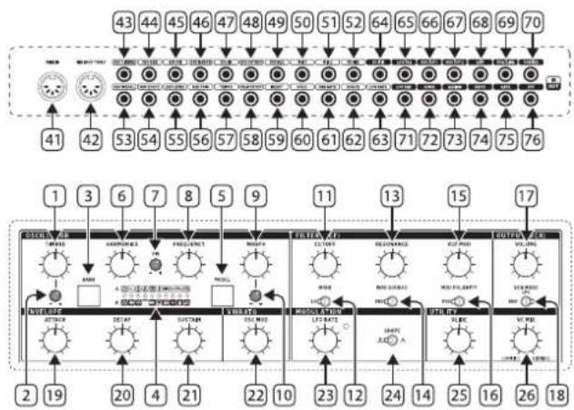
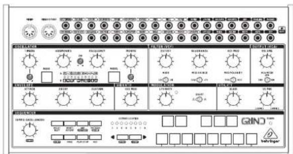
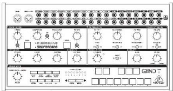
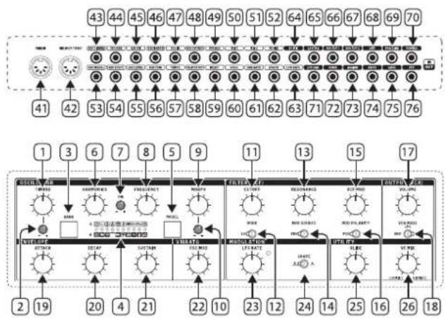
GRIND Controls
EN Step 2: Controls
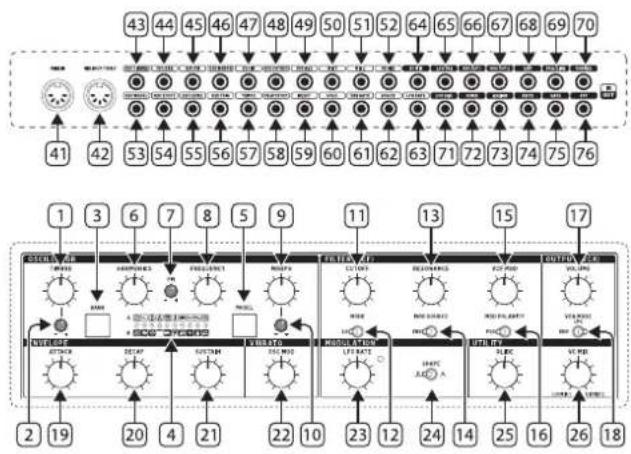
Oscillator (VCO) Section
- TIMBRE knob - Function varies depending on the model selected, but generally sweeps from darker to brighter content.
- TIMBRE CV LEVEL – Attenuates the voltage received at the Timbre CV input. If the CV input is not patched, and a signal is received at the Trig input, this knob will instead control the amount of modulation from the internal envelope generator.
- BANK button – Toggles between Bank A, Bank B and Bank C models.
- MODEL LEDs - Indicate the current model via red LED for bank A, green LED for bank B, or yellow LED for bank C.
- MODEL button – Scrolls through the available models in the currently-active bank.
- HARMONICS knob – Function varies depending on the model selected, but generally adjusts frequency spread or tonal balance.
- FM CV LEVEL – Attenuates the voltage received at the FM CV input.
- FREQUENCY knob – Covers a range of 8 octaves, but can be narrowed down to 14 semitones.
- MORPH knob - Function varies depending on the model selected, but generally controls the character.
- MORPH CV LEVEL – Attenuates the voltage received at the Morph CV input. If the CV input is not patched, and a signal is received at the Trig input, this knob will instead control the amount of modulation from the internal envelope generator.
Filter (VCF) Section
The default VCF input is Output 1 from the VCO.
-
CUTOFF - Adjust the cutoff frequency of the filter.
-
MODE – Select the VCF filter type from low-pass, high-pass or LPG.
-
RESONANCE – Adjust the amount of enhancement given to the signals at the cutoff frequency.
-
MOD SOURCE – Select the modulation source of the VCF from the envelope generator or the LFO.
-
VCF MOD – Adjust the depth of VCF modulation.
-
MOD POLARITY – Select the polarity of the VCF modulation.
Output (VCA) Section
-
VOLUME – Adjust the overall synthesizer output level.
-
VCA MODE – Select envelope, and the VCA is modulated by the envelope. In the ON position, the VCA output is the last key played, and is independent of envelope. Select LPG to replace the VCA with a Low Pass Gate.
Envelope Section
-
ATTACK – Control the amount of time taken to reach the maximum level after a key is pressed.
-
DECAY – Control the amount of time taken to decay from the current level to minimum.
-
SUSTAIN – Control the level of the envelope that is sustained after the attack time has been reached.
Vibrato Section
- VIBRATO - Control the amount of modulation to the oscillator, by default this controls the level of frequency modulation from the LFO.
Modulation Section
-
LFO RATE – Adjust the frequency of the low frequency oscillator. The LED will flash at the LFO rate.
-
SHAPE – Select the LFO waveform from square wave or triangular wave.
Utility Section
-
GLIDE - Adjust the amount of Glide time (Portamento), between notes on the keyboard. (If SHIFT is held, then the knob also adjusts the "ratchet" during sequencer operation.)
-
VC MIX – Adjust the VC MIX from LO/Mix 1 to HI/Mix 2. This control requires patch cords to operate, as it is outside of the internal synthesizer signal path.
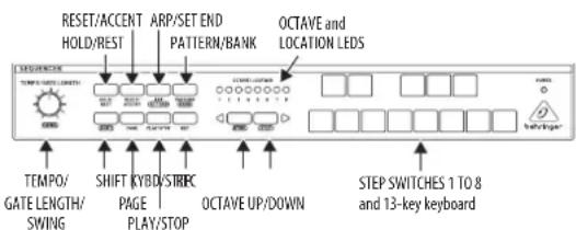
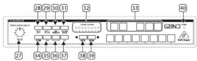
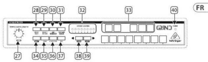
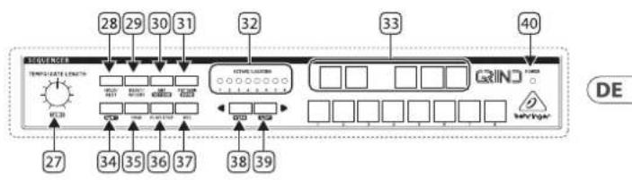
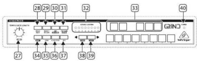
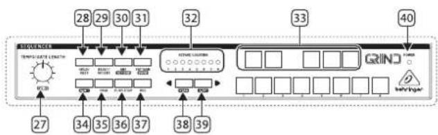
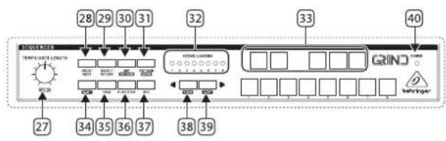
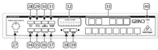
Sequencer Section
-
TEMPO/GATE LENGTH – This controls the sequencer and ARP tempo when the clock source is set to internal. If USB or MIDI clock is used, it also controls the value of clock division. During step editing, it controls the gate length. If SHIFT is held and sequencer played, then it also adjusts the swing. If SHIFT is held and ARP played, then it also adjusts the ARP gate length.
-
HOLD/REST - During pattern playback, this allows you to hold the current step. During step editing, it allows you to enter a rest. During ARP mode, it allows you to enter/exit ARP-Hold mode. During keyboard use, it allows you to hold the keys. (A footswitch connected to the HOLD input will also do this.)
- RESET/ACCENT – During playback, this allows you to reset the pattern back to step 1. During step editing, you can add an accent to a step.
- ARP (SET END) – In ARP mode, an arpeggio will play, based on the held notes using the GRIND's 13 keyboard switches. Double-press ARP, or press HOLD and ARP, to play and hold an arpeggio. In Sequencer mode, pressing SHIFT and SET END together, followed by a STEP switch, will allow that step to become the end of the current pattern.
- ATTERN (BANK) – This button is used to access either the current pattern, or bank number, as follows:
PATTERN: Press PATTERN, and one of the 8 LOCATION LEDs will show the current pattern number (from 1 to 8). To change to a different pattern number, keep the PATTERN button held down and press any of the STEP buttons (1 to 8), or press
BANK: Press SHIFT and PATTERN, and one of the 8 LOCATION LEDs will show the current bank number (from 1 to 8). To change to a different bank number, keep both SHIFT and BANK held down, and press any of the STEP buttons (1 to 8), or press
28 29GRUNDStart Guide
-
OCTAVE/LOCATION – These multi-colored LEDs show various details, such as the Octave, PATTERN number, BANK number, current PAGE, and GATE LENGTH.
-
KEYBOARD/STEP SWITCHES – These multifunction switches allow you to view and select individual pattern steps, select a pattern number, select a pattern bank. They are used during recording of a pattern to show the current step. Active steps are illuminated with a steady red LED, and the current step flashes red.
The switches are laid out as a 13-note keyboard. The octave can be moved up and down by pressing the
-
SHIFT - This is used to access the secondary features of some of the other sequencer controls, such as SET END, BANK, SWING, KYDB, and STEP. Hold down SHIFT and the other switch at the same time. For example SHIFT + PATTERN (BANK) will show the current BANK number in the LOCATOR LEDs.
-
PAGE – Each pattern can be up to 32 steps in length. This switch allows you to show each of the 4 pages of 8 steps each. The LOCATION LEDs 1 to 4, show which page you are on. If a pattern is playing, the STEP LEDs will show the steps in use on the current page.
-
PLAY/STOP - Starts or stops the playback of the pattern. If SHIFT is held at the same time, then this is the start of the pattern saving procedure.
-
REC - Press this to begin the recording of a new pattern. This is also used with SHIFT during the pattern saving procedure.
-
KYBD - Press SHIFT + KYBD to change the sequencer to keyboard mode. Press to change the 13-note keyboard octave.
- STEP - Press SHIFT + STEP to change the sequencer to STEP mode. Press to change the 13-note keyboard octave.
- POWER - Indicates that power is supplied to the unit and the rear-panel power switch is on.
MIDI Section
- MIDI IN - This 5-pin DIN jack receives MIDI data from an external source. This will commonly be a MIDI keyboard, an external hardware sequencer, a computer equipped with a MIDI interface, etc.
- MIDI OUT/THRU – Passes through MIDI data received at the MIDI INPUT and sends MIDI data to an application.
Patchbay (3.5 mm TS connections) Input Section
- OSC TIMBRE CV - Control the Timbre parameter via external control voltage.
- OSC HAR CV - Control the Harmonics parameter via external control voltage.
- OSC FM - Control the FM parameter via external control voltage.
- OSC MORPH CV - Control the Morph parameter via external control voltage.
- VCF IN – External audio input to the VCF.
- VCF CUTOFF - VCF cutoff frequency CV.
- VCF RES – VCF Resonance CV.
-
MIX 1 - Mix 1 CV in, connected internally to VC MIX.
-
MIX 2 – Mix 2 CV in, connected internally to VC MIX.
- VC MIX – VC mix control CV in, connected internally to VC MIX.
- OSC MODEL CV – Allows model selection to be made remotely via external control voltage.
- OSC CV – Oscillator pitch CV, at 1 V/octave.
- OSC LEVEL – Opens the internal low-pass gate on the output signal, controlling both output level and brightness. Also triggers an accent when the physical or percussive models are active.
-
OSC TRIG – Performs several functions:
-
Triggers the internal envelope generator.
• Excites the physical and percussive models.
• Strikes the internal low-pass gate. -
Samples and holds the value of the Model CV input.
-
TEMPO – Sequencer tempo.
- PLAY/STOP – Sequencer play/stop.
- RESET – Sequencer reset.
- HOLD – Sequencer hold.
- ENV GATE – Envelope gate.
- VCA CV - VCA CV.
- LFO RATE – LFO frequency rate CV.
Patchbay (3.5 mm TS connections) Output Section
- VC MIX – VC mix output connected internally to VC MIX.
- LFO TRI - LFO triangular waveform output.
- OSC OUT 1 – Sends the main processed signal via 3.5 mm TS cable.
- OSC OUT 2 – Sends an alternate or variant of the Out 1 signal via 3.5 mm TS cable.
- ENV – Envelope output.
- VCA/LINE – Connect this 3.5 mm TS output to the line-level audio input of your system. Make sure the volume is turned down and the system is turned off before making connections.
- PHONES – Connect your headphones to this 3.5 mm TRS output. Make sure the volume is turned down before putting on headphones.
- LFO SQU - LFO square waveform output.
- NOISE – noise output.
- ASSIGN – assign output.
- KB CV – keyboard CV output.
- GATE - gate output.
- VCF - VCF output.
30 31G#lndDStart Guide
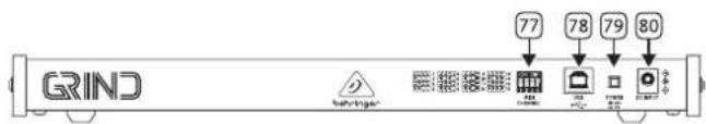
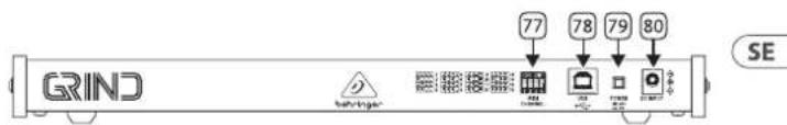
Rear Panel
-
MIDI CHANNEL – These 4 switches allow you to set the MIDI Channel number from 1 to 16, as shown in the chart.
-
USB PORT – This USB type B jack allows connection to a computer. The GRIND will show up as a class-compliant USB MIDI device, capable of supporting MIDI in and out.
- USB MIDI IN - accepts incoming MIDI data from an application.
- USB MIDI OUT - sends MIDI data to an application.
-
POWER – Turn the synthesizer on or off. Make sure all the connections are made before turning on the unit.
-
DC INPUT - Connect the supplied 12V DC power adapter here. The power adapter can be plugged into an AC outlet capable of supplying from 100V to 240V at 50Hz / 60Hz . Use only the power adapter supplied.
Low Pass Gate and Envelope
To adjust the Low Pass Gate press and hold the Bank button (3) and use the Timbre control to adjust its response from being a VCA when fully clockwise to being a true low pass gate when fully counter-clockwise or the Morph control (9) to adjust its ring time and increase the decay of the internal envelope. The settings are shown by the number of yellow LEDs lit, from 1 – 4.
Low Pass Gates reduce level and cutoff simultaneously, resulting in the signal losing high frequency content as it gets quieter.
Frequency Range
Press and hold the Model button (5) and use the Harmonics control (5) to set the range of the Frequency control (8). The number of lit LEDs corresponds to the range. 1 LED represents C0 +/- 7 semitones, 2 LEDs C1 +/- 7 semitones until 8 LEDs represents C7 +/- 7 semitones. When all LEDs are lit then the Frequency control has an eight octave range covering C0 to C8.
GRIND Getting Started
EN Step 3: Getting started
OVERVIEW
This 'getting started' guide will help you set up the GRIND analog synthesizer and briefly introduce its capabilities.
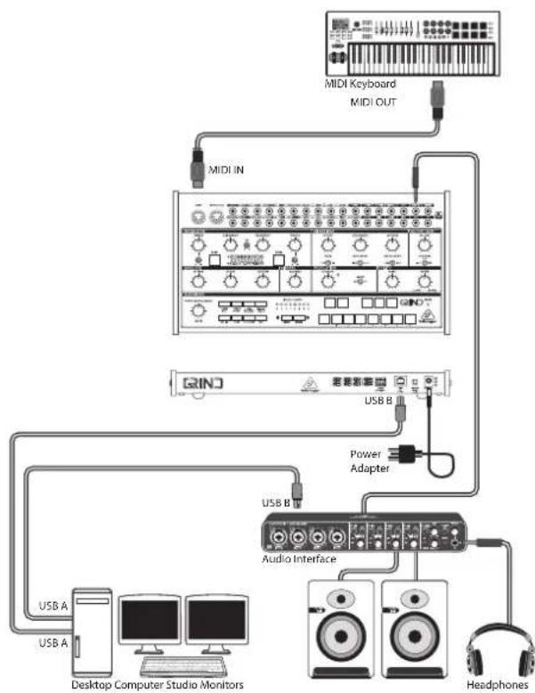
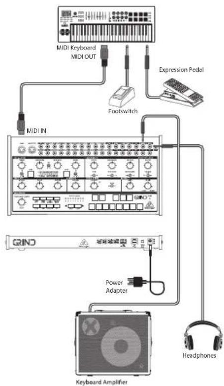
CONNECTION
To connect the GRIND to your system, please consult the connection guide earlier in this document.
SOFTWARE SETUP
The GRIND is a USB Class Compliant MIDI device, and so no driver installation is required. The GRIND does not require any additional drivers to work with Windows and MacOS.
HARDWARE SETUP
Make all the connections in your system. Use the rear panel MIDI switches to set the GRIND to a unique MIDI channel in your system. Connect an external MIDI keyboard directly to the GRIND MIDI IN 5-pin DIN type input.
Apply power to the GRIND using the supplied power adapter only. Ensure your sound system is turned down. Turn on the GRIND rear panel power switch.
WARM UP TIME
We recommend leaving 15 minutes or more time for the GRIND to warm up before recording or live performance. (Longer if it has been brought in from the cold.) This will allow the precision analog circuits time to reach their normal operating temperature and tuned performance.
FILTER (VCF) SECTION
Play with the cutoff frequency, and resonance controls, and listen to their effects on the sound.
The classic 24 dB/octave high pass and low pass filters allow a great deal of control over the sounds created by GRIND.
The high-pass filter reduces the level of signals that are below the cutoff frequency. It effectively reduces the level of the fundamental, and lower order harmonics.
The low-pass filter reduces the level of signals that are above the cutoff frequency. It reduces the levels of the higher-order harmonics.
The resonance control gives an enhancement to the signals at the crossover frequency.
The amount of VCF modulation can be varied with the VCF MOD control, and also the polarity can be reversed. For example, if modulation increases the cutoff frequency, then negative polarity will decrease it.
The VCF modulation source can either be the envelope or the LFO.
All these features, in addition to using the patch bay, allows for a great deal of flexibility in sound creation.
MODULATION SECTION
The low frequency oscillator can be used to modulate the VCO and the VCF. The LFO frequency can be varied, and the waveform selected from square or triangular. An LED indicates the LFO rate.
32 33GUNDStart Guide
ENVELOPE GENERATOR SECTION
The envelope generator can be used to modulate the cutoff frequency in the VCF section, and the voltage controlled amplifier (VCA). Envelope also can be used to modulate the VCO frequency and pulse width.
The controls for attack time, sustain level and decay time, allow you to adjust the envelope shape through a wide range.
PATCH BAY SECTION
This section allows you the versatility to create many different sounds, with an endless variety of options and configurations.
The VC MIX control is like having a separate mini-mixer or variable voltage source. It operates independently from the main signal path. It allows you to adjust a mix between the patchbay MIX 1 input and MIX 2 input, with possible modulation control from the VC MIX CV input. The patchbay VC MIX output can then be used to connect to other inputs in the patch bay.
If there are no MIX 1 or MIX 2 inputs connected, then the VC MIX output will vary from 0 V (fully left) to +5 V (fully right). Experiment with this by connecting the VC MIX output to an input, and varying the VC MIX control.
Caution: Do not overload the 3.5 mm inputs. They can only accept the correct level of voltages as shown in the specification tables. The 3.5 mm outputs should only be connected to inputs capable of receiving the output voltages. Failure to follow these instructions may damage the GRIND or external units.
SEQUENCER SECTION
The sequencer is described in further detail in this document. It also features an arpeggiator, and a 13-key keyboard.
OUTPUT (VCA) SECTION
Use the main volume control to adjust the sound level in your headphones or speaker system.
Keep the level down low when first putting on headphones.
Keep the GRIND power turned off when making any connections.
Turn on the GRIND before turning on any power amplifiers, and turn it off last. This will help prevent any turn on or turn off "pops or thumps" in your speakers.
The output can be modulated using the envelope, or it can be on continuously, playing and holding the last note played, until the next note occurs.
ARPEGGIATOR
To use the arpeggiator, press the ARP switch in the sequencer section:
-
Press it once to play the arpeggiator. (It stops when notes are released.)
-
Press it twice, or press HOLD and ARP, to hold the arpeggio. (It continues when notes are released.)
The arpeggiator rate is set by the TEMPO/GATE LENGTH knob. The arpeggiator gate length is set by SHIFT + TEMPO/GATE LENGTH.
The order in which the arpeggiator notes are played has 8 options, which can be changed by pressing and holding SHIFT (34) and using keys 1 - 8 to select the required mode:
-
UP 1
-
DOWN 1
-
DOWN and UP
-
RANDOM
-
UP (+1 Oct)
-
DOWN (+1 Oct)
-
UP (- 1 Oct)
-
DOWN (-1 Oct)
ACCENT
If you are playing a MIDI keyboard, the accent is automatically triggered when the velocity exceeds the threshold. (This accent velocity threshold can be adjusted, or this feature disabled, using the SynthTribe APP).
To use accent while playing, press the ACCENT switch:
-
Press and hold to play the note with accent status. (It stops when the switch is released.)
-
Press it twice to play and hold the accent status. (The LED flashes slowly.)
FIRMWARE UPDATE
The SynthTribe App is available as a free download from the GRIND product page of our website: behringer.com. The latest file can be downloaded and stored on your computer, and then used to update the GRIND if required.
34 35GRUNDStart Guide
GRIND Sequencer Operation
OVERVIEW
The following details show some of the basic operation of the sequencer. You can create a short pattern of 2 or 3 steps, before trying more complex patterns. Adjust a single parameter at a time, such as gate length, ratchet, accent, glide, rest, tie, or swing, and then listen to its effect during playback.
It will help to choose a simple setting for the synthesizer, and no modulation of the VCO or VCF.
RECORDING A SIMPLE PATTERN
- Press SHIFT and <KYBD to select the keyboard mode.
- Initialise the current pattern by pressing SHIFT, RESET, and PATTERN at the same time. This will delete any previous steps of the current pattern.
- Press REC, and the STEP 1 switch LED will begin flashing, indicating this is the current step about to be added and edited. (If you cannot select REC, then repeat step 1.)
- Press any note on the GRIND keyboard, or a rest as shown below. The
switches can be used to change the octave., indicated by 8 OCTAVE / LOCATION LEDs lit red. -
To enter a rest instead of a note, press the HOLD/REST switch. When a rest is added, the LOCATOR LED 8 will light.
-
Press further notes. The next STEP switch LED will be flashing after each note or rest has been added.
- The gate length of a step can be adjusted using the TEMPO/GATE LENGTH control. The LOCATOR LEDs will turn red, showing the gate length from 1 to 8. If set to 8, this creates a tie with the next step. If the next step is the same note, this creates a longer note, as the 2 steps are tied.
- To create a "Ratchet," hold SHIFT, and turn the GLIDE control. The locator LEDs will show the number of ratchets from 1 to 4, in yellow. For example, with a setting of 4, the single step is split into 4 equal parts. When a ratchet is applied, the LOCATION LED 6 will light.
- To turn the GLIDE on for a step, turn up the GLIDE control. To turn off, turn it all the way down. When GLIDE is on for a step, the LOCATION LED 5 will light.
- To increase the brightness or accent, press the RESET/ ACCENT switch. When an accent is applied, the LOCATION LED 7 will light.
- Press REC when you have finished creating the pattern. It is not saved yet, but it can be played back. Caution: Do not turn off the unit, or create a new pattern, or the current unsaved pattern will be lost.
PLAYING A PATTERN
- Press PLAY/STOP to listen to the current pattern.
- If you decide not to save it, you can repeat the recording steps above to record a new pattern. Alternatively, press PATTERN and RESET to recall the currently saved pattern, and discard any changes.
- If you decide to save the pattern, you must follow the "SAVING A PATTERN" procedure shown below, or it will not remain in memory if a new pattern is begun, or the power is turned off.
- To create a SWING for this pattern, hold SHIFT and adjust the TEMPO/GATE LENGTH control. In the center position, no swing is applied, if turned down, only the off-beats will play, and if all the way up, only the on-beats will play. The SWING setting for the pattern is saved when the pattern is saved as shown below.
- While playing a pattern, you can:
Press HOLD/REST to hold the current step.
Press RESET/ACCENT to return to step 1.
Press SHIFT and any STEP, and you can edit the gate length, rest, accent, ratchet, glide but not note. Press SHIFT and the same STEP again to exit step edit. (If playback is paused, the same operation can edit the note as well.
Press PAGE to view the pattern page from 1 to 4. Press SHIFT and PAGE to return to automatic page turning.
Press SHIFT and ARP/SETEND and a STEP to change the sequence end step.
PLAY/STOP to pause playback.
- Press PLAY/STOP.
- Note: To play in reverse, press SHIFT and PLAY/STOP.
SAVING A PATTERN
- Press and hold SHIFT + PLAY/STOP for 2 seconds until the LOCATOR LED of the current pattern number begins to flash green slowly.
- Press a STEP switch 1 to 8 to select the new desired pattern number.
- Press PATTERN + STEP switch 1 to 8 to select the desired bank number.
- Press SHIFT + REC to save the pattern and exit the save mode.
RECALLING A SAVED PATTERN
- Press and hold PATTERN. The LOCATION LED will show the current pattern number. Use the
switches to move up and down through the patterns 1 to 8, or press a STEP switch 1 to 8. You can also do this while a pattern is playing. - Press and hold SHIFT and PATTERN. The LOCATION LED will show the current bank number. Use the
switches to move up and down through the banks 1 to 8, or press a STEP switch 1 to 8. You can also do this while a pattern is playing. - Press PLAY/STOP to play back the current pattern.
- During playback, the LOCATION LEDs will show the current page of the pattern (1 to 4), and the STEP Switch LEDs will show the steps moving.
36 37GRINDDStart Guide
LIVE PERFORMANCE
During playback, temporary adjustments can be made as follows. (None of these are saved with the pattern.)
- To add Ratchet to all steps of the pattern, press SHIFT and adjust the GLIDE control.
- To add SWING, press SHIFT and adjust the TEMPO control.
- To mute the pattern, press SHIFT + HOLD/REST.
- To add an accent to all steps, press SHIFT + RESET/ACCENT.
- Use the
switches to change the octave. The LEDs will show the current Octave in red.
EDITING A PATTERN
- To edit a pattern in Keyboard mode, press REC. The STEP switch LEDs will light.
- Press PAGE to select the pattern page from 1 to 4 to be edited. The green LOCATION LEDs 1 to 4 will show the current page and the PAGE button LED lit to indicate the page is locked (press SHIFT and PAGE to unlock).
- Press SHIFT and the STEP switch you want to edit. You can enter a new note, or a rest, and adjust any of the other parameters such as ratchet, glide on/off, and so on.
- Press SHIFT and the next STEP switch to be edited. (The steps will not automatically advance to the next step in line; you can choose which steps to edit next.)
- Press REC to exit the editing mode.
- Press PLAY/STOP to listen to the edited pattern.
- Remember to save the pattern using the "SAVING A PATTERN" procedure above.
CREATING A PATTERN IN STEP MODE
- Press SHIFT and STEP> to select the Sequencer's STEP mode. The flashing LOCATION LED will turn from green (Keyboard mode) to yellow (Step mode).
- Initialise the current pattern by pressing SHIFT, RESET, and PATTERN at the same time. This will delete any previous steps of the current pattern. (If you want to use the current pattern instead, then do not initialise it.)
- Press PAGE to move to a desired page of your pattern. Then press SET END and a STEP switch to choose the length of the pattern. For example, if you are on page 1 and press SET END + 8, then the pattern length is 8 steps. If you press PAGE and reach page 4, and press SET END + 8, then the pattern will be 32 steps long (4 pages of 8 steps each).
- When the desired SET END is selected, all the STEP switch LEDs up to that step will be on solid red.
- Press SHIFT and any one of the STEP switches at the same time. It will begin to flash, indicating it is the current step about to be edited. You can now add a note, or a rest, or any of the other functions described above in the Keyboard mode, such as Ratchet, Glide, Accent, change gate length and so on.
- Press SHIFT and the current STEP switch to finish editing that step. It will stop flashing.
- Repeat procedure steps 5 and 6 above, until all your required steps are good.
- Press PLAY/STOP to play the pattern.
- While playing, you can add temporary adjustments as shown in the "LIVE PERFORMANCE" procedure above.
SAVING A PATTERN IN STEP MODE
Save the pattern using the "SAVING A PATTERN" procedure shown above for the KEYBOARD mode.
Caution: Do not turn off the unit, or create a new pattern, or the current unsaved pattern will be lost.
38 39GRUNDStart Guide
GRIND Parameter Selection Mode
The parameters may be changed using the following procedure:
-
Press SHIFT+ HOLD/REST + 8 to enter the setting mode. The LOCATION LED 1 will blink yellow.
-
Press
to select pages 1 to 4. The yellow LOCATION LED shows the current page: -
Page 1 allows you to select the tempo input mode, 1 to 5. (Please see Programming Tempo Input Modes, below)
-
Page 2 allows you to select the assign output mode, 1 to 16. (Please see Assignable Output Mode, below)
-
Page 3 allows you to select the clock type mode, 1 to 5. (Please see Clock Type Modes, below)
-
Page 4 allows you to select the clock edge mode, 1 to 2. (Please see Clock Edge Modes, below)
-
Press STEP switches 1 to 8 to select numeric values from 1 to 8. The current value is indicated by a green LOCATION LED.
-
To access values 9 to 16, press SHIFT + STEP switch 1 to 8. The current value is shown by a red LOCATION LED.
-
Note: If a setting is on the same LED number as the current page LED, then the LED will flash alternately between the yellow page color and the green or red parameter color.
-
Press SHIFT + HOLD/REST + 8 to exit the setting mode, and save any parameter changes.
-
More parameters can be changed using the SynthTribe App.
Programming Tempo Input Modes:
-
1PPS
-
2PPQ
-
24PPQN
-
48PPQN
-
CV
Assignable Output Modes:
-
Sequencer Accent
-
Sequencer Clock
-
Sequencer Clock/2
-
Sequencer Clock/4
-
Sequencer Step Ramp
-
Sequencer Step Saw
-
Sequencer Step Triangle
-
Sequencer Step Random
-
Sequencer Step 1 Trigger Output
-
MIDI Velocity
-
MIDI Channel Pressure
-
MIDI Pitch Bend
-
MIDI CC1
-
MIDI CC2
-
MIDI CC4
-
MIDI CC7
Clock Type Modes:
-
INTERNAL
-
MIDI DIN
-
MIDI USB
-
EXTERNAL TRIGGER
-
AUTO (clock priority: TRIG > MIDI USB > MIDI DIN > INTERNAL)
Clock Edge Modes:
-
Fall
-
Rise
40 41GRINDDStart Guide
GRIND Conexión
ES Paso 1: Conexión

flowchart
graph TD
    A["43"] --> B["1"]
    C["44"] --> D["3"]
    E["45"] --> F["6"]
    G["46"] --> H["7"]
    I["47"] --> J["8"]
    K["48"] --> L["9"]
    M["49"] --> N["10"]
    O["50"] --> P["11"]
    Q["51"] --> R["12"]
    S["52"] --> T["13"]
    U["64"] --> V["14"]
    W["65"] --> X["15"]
    Y["66"] --> Z["16"]
    AA["67"] --> AB["17"]
    AC["68"] --> AD["18"]
    AE["69"] --> AF["19"]
    AG["70"] --> AH["20"]
    AI["41"] --> AJ["3"]
    AK["42"] --> AL["4"]
    AM["53"] --> AN["5"]
    AO["54"] --> AP["6"]
    AQ["55"] --> AR["7"]
    AS["56"] --> AT["8"]
    AU["57"] --> AV["9"]
    AW["58"] --> AX["10"]
    AY["60"] --> AZ["11"]
    BA["61"] --> BB["12"]
    BC["62"] --> BD["13"]
    BE["63"] --> BF["14"]
    BG["71"] --> BH["15"]
    BI["72"] --> BJ["16"]
    BK["73"] --> BL["17"]
    BM["74"] --> BN["18"]
46 47GRUNDStart Guide
GRIND Controles
ES Paso 2: Controles
-
HASTA 1
-
ABAJO 1
-
ABAJO y ARRIBA
-
ALEATORIO
-
UP (+ 1 Oct)
-
DOWN (+1 Oct)
-
UP (-1 Oct)
-
DOWN (-1 Oct)
ACENTO
VISIÓN GENERAL
Assignable Output Modes:
- Sequencer Accent
- Sequencer Clock
- Sequencer Clock/2
- Sequencer Clock/4
- Sequencer Step Ramp
- Sequencer Step Saw
- Sequencer Step Triangle
- Sequencer Step Random
- Sequencer Step 1 Trigger Output
- MIDI Velocity
- MIDI Channel Pressure
- MIDI Pitch Bend
- MIDI CC1
- MIDI CC2
- MIDI CC4
- MIDI CC7
Clock Type Modes:
- INTERNAL
- MIDI DIN
- MIDI USB
- EXTERNAL TRIGGER
- AUTO (clock priority: TRIG > MIDI USB > MIDI DIN > INTERNAL)
Clock Edge Modes:
- Fall
- Rise
60 61GRNDStart Guide
GRIND Connexions
flowchart
graph TD
    A["43"] --> B["1"]
    C["44"] --> D["3"]
    E["45"] --> F["6"]
    G["46"] --> H["7"]
    I["47"] --> J["8"]
    K["48"] --> L["9"]
    M["49"] --> N["10"]
    O["50"] --> P["11"]
    Q["51"] --> R["12"]
    S["52"] --> T["13"]
    U["64"] --> V["14"]
    W["65"] --> X["15"]
    Y["66"] --> Z["16"]
    AA["67"] --> AB["17"]
    AC["68"] --> AD["18"]
    AE["69"] --> AF["19"]
    AG["70"] --> AH["20"]
    AI["41"] --> AJ["3"]
    AK["42"] --> AL["5"]
    AM["53"] --> AN["6"]
    AO["54"] --> AP["7"]
    AQ["55"] --> AR["8"]
    AS["56"] --> AT["9"]
    AU["57"] --> AV["10"]
    AW["58"] --> AX["11"]
    AY["59"] --> AZ["12"]
    BA["60"] --> BB["13"]
    BC["61"] --> BD["14"]
    BE["62"] --> BF["15"]
    BG["63"] --> BH["16"]
    BI["71"] --> BJ["17"]
    BK["72"] --> BL["18"]

66 67GRUNDStart Guide
GRIND Réglages
APERÇU
Assignable Output Modes:
-
Sequencer Accent
-
Sequencer Clock
-
Sequencer Clock/2
-
Sequencer Clock/4
-
Sequencer Step Ramp
-
Sequencer Step Saw
-
Sequencer Step Triangle
-
Sequencer Step Random
-
Sequencer Step 1 Trigger Output
-
MIDI Velocity
-
MIDI Channel Pressure
-
MIDI Pitch Bend
-
MIDI CC1
-
MIDI CC2
-
MIDI CC4
-
MIDI CC7
Clock Type Modes:
-
INTERNAL
-
MIDI DIN
-
MIDI USB
-
EXTERNAL TRIGGER
-
AUTO (clock priority: TRIG > MIDI USB > MIDI DIN > INTERNAL)
Clock Edge Modes:
-
Fall
-
Rise
80 81GRINDStart Guide
GRIND Verkabelung

flowchart
graph TD
    A["43"] --> B["1"]
    C["44"] --> D["3"]
    E["45"] --> F["6"]
    G["46"] --> H["7"]
    I["47"] --> J["8"]
    K["48"] --> L["9"]
    M["49"] --> N["10"]
    O["50"] --> P["11"]
    Q["51"] --> R["13"]
    S["52"] --> T["15"]
    U["64"] --> V["17"]
    W["65"] --> X["17"]
    Y["66"] --> Z["17"]
    AA["67"] --> AB["17"]
    AC["68"] --> AD["17"]
    AE["69"] --> AF["17"]
    AG["70"] --> AH["17"]

    subgraph System_Control
        B --> B1["41"]
        D --> D1["42"]
        F --> F1["53"]
        H --> H1["54"]
        I --> I1["55"]
        J --> J1["56"]
        K --> K1["57"]
        L --> L1["58"]
        M --> M1["59"]
        N --> N1["60"]
        O --> O1["61"]
        P --> P1["62"]
        Q --> Q1["63"]
        R --> R1["71"]
        S --> S1["72"]
        T --> T1["73"]
        U --> U1["74"]
        V --> V1["75"]
        W --> W1["76"]
    end

    subgraph Control Panel
        A --> A1["1"]
        B --> A2["3"]
        C --> A3["6"]
        D --> A4["7"]
        E --> A5["8"]
        F --> A6["9"]
        G --> A7["10"]
        H --> H1["11"]
        I --> I1["13"]
        J --> J1["15"]
        K --> K1["17"]
        L --> L1["17"]
        M --> M1["17"]
        N --> N1["17"]
        O --> O1["17"]
        P --> P1["17"]
        Q --> Q1["17"]
        R --> R1["17"]
        S --> S1["17"]
        T --> T1["17"]
        U --> U1["17"]
        V --> V1["17"]
        W --> W1["17"]
    end

    subgraph Control Panel
        A --> A2
        B --> A3
        C --> A4
        D --> A5
        E --> A6
        F --> A7
        G --> A8
        H --> A9
        I --> A10
        J --> A11
        K --> A12
        L --> A13
        M --> A14
        N --> A15
        O --> A16
        P --> A17
        Q --> A18
        R --> A19
        S --> A20
        T --> A21
        U --> A22
        V --> A23
        W --> A24
        X --> A25
        Y --> A26
        Z --> A27
        AA --> A28
        AB --> A29
        AC --> A30
        AD --> A31
    end

86 87GRUND Start Guide
GRIND Bedienelemente
DE Schritt 2: Bedienelemente
ÜBERSICHT
Assignable Output Modes:
-
Sequencer Accent
-
Sequencer Clock
-
Sequencer Clock/2
-
Sequencer Clock/4
-
Sequencer Step Ramp
-
Sequencer Step Saw
-
Sequencer Step Triangle
-
Sequencer Step Random
-
Sequencer Step 1 Trigger Output
-
MIDI Velocity
-
MIDI Channel Pressure
-
MIDI Pitch Bend
-
MIDI CC1
-
MIDI CC2
-
MIDI CC4
-
MIDI CC7
Clock Type Modes:
-
INTERNAL
-
MIDI DIN
-
MIDI USB
-
EXTERNAL TRIGGER
-
AUTO (clock priority: TRIG > MIDI USB > MIDI DIN > INTERNAL)
Clock Edge Modes:
-
Fall
-
Rise
100 100NDck Start Guide
GRIND Conexões
PT

flowchart
graph TD
    A["43"] --> B["1"]
    C["44"] --> D["3"]
    E["45"] --> F["6"]
    G["46"] --> H["7"]
    I["47"] --> J["8"]
    K["48"] --> L["9"]
    M["49"] --> N["10"]
    O["50"] --> P["11"]
    Q["51"] --> R["12"]
    S["52"] --> T["13"]
    U["64"] --> V["14"]
    W["65"] --> X["15"]
    Y["66"] --> Z["16"]
    AA["67"] --> AB["17"]
    AC["68"] --> AD["18"]
    AE["69"] --> AF["19"]
    AG["70"] --> AH["20"]
    AI["41"] --> AJ["21"]
    AK["42"] --> AL["22"]
    AM["53"] --> AN["23"]
    AO["54"] --> AP["24"]
    AQ["55"] --> AR["25"]
    AS["56"] --> AT["26"]
    AU["57"] --> AV["27"]
    AW["58"] --> AX["28"]
    AY["59"] --> AZ["29"]
    BA["60"] --> BB["30"]
    BC["61"] --> BD["31"]
    BE["62"] --> BF["32"]
    BG["63"] --> BH["33"]
    BI["71"] --> BJ["34"]
    BK["72"] --> BL["35"]
    BM["73"] --> BN["36"]
    BO["74"] --> BP["37"]
    BQ["75"] --> BR["38"]
    BS["76"] --> BT["39"]

106 107NDck Start Guide
GRIND Controles
PT Passo 2: Controles
VISÃO GERAL
Assignable Output Modes:
- Sequencer Accent
- Sequencer Clock
- Sequencer Clock/2
- Sequencer Clock/4
- Sequencer Step Ramp
- Sequencer Step Saw
- Sequencer Step Triangle
- Sequencer Step Random
- Sequencer Step 1 Trigger Output
- MIDI Velocity
- MIDI Channel Pressure
- MIDI Pitch Bend
- MIDI CC1
- MIDI CC2
- MIDI CC4
- MIDI CC7
Clock Type Modes:
- INTERNAL
- MIDI DIN
- MIDI USB
- EXTERNAL TRIGGER
- AUTO (clock priority: TRIG > MIDI USB > MIDI DIN > INTERNAL)
Clock Edge Modes:
- Fall
- Rise
120 12PQ Quick Start Guide
GRIND Allacciare

flowchart
graph TD
    A["43"] --> B["Weather Icon"]
    C["44"] --> D["Weather Icon"]
    E["45"] --> F["Weather Icon"]
    G["46"] --> H["Weather Icon"]
    I["47"] --> J["Weather Icon"]
    K["48"] --> L["Weather Icon"]
    M["49"] --> N["Weather Icon"]
    O["50"] --> P["Weather Icon"]
    Q["51"] --> R["Weather Icon"]
    S["52"] --> T["Weather Icon"]
    U["64"] --> V["Weather Icon"]
    W["65"] --> X["Weather Icon"]
    Y["66"] --> Z["Weather Icon"]
    AA["67"] --> AB["Weather Icon"]
    AC["68"] --> AD["Weather Icon"]
    AE["69"] --> AF["Weather Icon"]
    AG["70"] --> AH["Weather Icon"]

    subgraph Time_States
        AI["1"] --> AJ["3"]
        AK["6"] --> AL["7"]
        AM["8"] --> AN["5"]
        AO["9"] --> AP["11"]
        AQ["13"] --> AR["15"]
        AS["17"] --> AT["OUTDO"]
    end

    subgraph Condition_Levels
        AU["1"] --> AV["2"]
        AW["3"] --> AX["4"]
        AY["6"] --> AZ["7"]
        BA["8"] --> BB["9"]
        BC["11"] --> BD["13"]
        BE["15"] --> BF["17"]
        BG["OUTDO"] --> BH["OUTDO"]
    end

    subgraph Time_States
        BI["1"] --> BJ["2"]
        BK["3"] --> BL["4"]
        BM["6"] --> BN["7"]
        BO["8"] --> BP["9"]
        BQ["11"] --> BR["13"]
        BS["15"] --> BT["17"]
        BU["OUTDO"] --> BV["OUTDO"]
    end

    subgraph Condition_Levels
        BW["1"] --> BX["2"]
        BY["3"]
        BZ["4"]
        CA["5"]
        CB["6"]
        CC["7"]
        CD["8"]
        DE["9"]
        FD["11"]
        DG["13"]
        DH["15"]
        DI["17"]
        DJ["OUTDO"] --> DK["OUTDO"]
    end

IT
126 127 Quick Start Guide
GRIND Controlli
-
TEMPO - Tempo sequencer.
-
PLAY/STOP – Sequencer play/stop.
-
RESET – Reset del sequencer.
-
HOLD – Sequencer hold.
-
ENV GATE – Cancello portabuste.
-
VCA CV - VCA CV.
-
Tasso LFO – CV tasso di frequenza IFO.
PANORAMICA
Assignable Output Modes:
- Sequencer Accent
- Sequencer Clock
- Sequencer Clock/2
- Sequencer Clock/4
- Sequencer Step Ramp
- Sequencer Step Saw
- Sequencer Step Triangle
- Sequencer Step Random
- Sequencer Step 1 Trigger Output
- MIDI Velocity
- MIDI Channel Pressure
- MIDI Pitch Bend
- MIDI CC1
- MIDI CC2
- MIDI CC4
- MIDI CC7
Clock Type Modes:
- INTERNAL
- MIDI DIN
- MIDI USB
- EXTERNAL TRIGGER
- AUTO (clock priority: TRIG > MIDI USB > MIDI DIN > INTERNAL)
Clock Edge Modes:
- Fall
- Rise
140 14Rlock Start Guide
GRIND Aansluiten
NL Stap 2: Bediening


flowchart
graph TD
    A["1"] --> B["1"]
    C["3"] --> D["3"]
    E["6"] --> F["6"]
    G["7"] --> H["7"]
    I["8"] --> J["8"]
    K["5"] --> L["5"]
    M["9"] --> N["9"]
    O["11"] --> P["11"]
    Q["13"] --> R["13"]
    S["15"] --> T["15"]
    U["17"] --> V["17"]
    W["OUTDO FOR ALL"]
    X["OUTDO FOR CHAP"]
    Y["OUTDO FOR FLIGHT"]
    Z["OUTDO FOR SEA"]
    AA["OUTDO FOR SEA"]
    AB["OUTDO FOR SEA"]
    AC["OUTDO FOR SEA"]
    AD["OUTDO FOR SEA"]
    AE["OUTDO FOR SEA"]
    AF["OUTDO FOR SEA"]
    AG["OUTDO FOR SEA"]
    AH["OUTDO FOR SEA"]
    AI["OUTDO FOR SEA"]
    AJ["OUTDO FOR SEA"]
    AK["OUTDO FOR SEA"]
    AL["OUTDO FOR SEA"]
    AM["OUTDO FOR SEA"]
    AN["OUTDO FOR SEA"]
    AO["OUTDO FOR SEA"]
    AP["OUTDO FOR SEA"]
    AQ["OUTDO FOR SEA"]
    AR["OUTDO FOR SEA"]
    AS["OUTDO FOR SEA"]
    AT["OUTDO FOR SEA"]
    AU["OUTDO FOR SEA"]
    AV["OUTDO FOR SEA"]
    AW["OUTDO FOR SEA"]

NL
146 147 Quick Start Guide
GRIND Bediening
NL Stap 2: Bediening
Assignable Output Modes:
-
Sequencer Accent
-
Sequencer Clock
-
Sequencer Clock/2
-
Sequencer Clock/4
-
Sequencer Step Ramp
-
Sequencer Step Saw
-
Sequencer Step Triangle
-
Sequencer Step Random
-
Sequencer Step 1 Trigger Output
-
MIDI Velocity
-
MIDI Channel Pressure
-
MIDI Pitch Bend
-
MIDI CC1
-
MIDI CC2
-
MIDI CC4
-
MIDI CC7
Clock Type Modes:
-
INTERNAL
-
MIDI DIN
-
MIDI USB
-
EXTERNAL TRIGGER
-
AUTO (clock priority: TRIG > MIDI USB > MIDI DIN > INTERNAL)
Clock Edge Modes:
-
Fall
-
Rise
160 161 Quick Start Guide
GRIND Anslutning
SE Steg 1: Anslutning
Studio-systemet

flowchart
graph TD
    A["MIDI Keyboard"] --> B["MIDI OUT"]
    B --> C["MIDI IN"]
    C --> D["USB B"]
    D --> E["Audio Interface"]
    E --> F["Headphones"]
    E --> G["Desktop Computer Studio Monitors"]
    E --> H["USB A"]
    E --> I["USB A"]


flowchart
graph TD
    A["1"] --> B["1"]
    C["3"] --> D["3"]
    E["6"] --> F["6"]
    G["7"] --> H["7"]
    I["8"] --> J["8"]
    K["5"] --> L["5"]
    M["9"] --> N["9"]
    O["11"] --> P["11"]
    Q["13"] --> R["13"]
    S["15"] --> T["15"]
    U["17"] --> V["17"]
    W["OUTDO"] --> X["OUTDO"]
    Y["DOWN"] --> Z["DOWN"]
    AA["TIME"] --> AB["TIME"]
    AC["TIME"] --> AD["TIME"]
    AE["TIME"] --> AF["TIME"]
    AG["TIME"] --> AH["TIME"]
    AI["TIME"] --> AJ["TIME"]
    AK["TIME"] --> AL["TIME"]
    AM["TIME"] --> AN["TIME"]
    AO["TIME"] --> AP["TIME"]
    AQ["TIME"] --> AR["TIME"]
    AS["TIME"] --> AT["TIME"]
    AU["TIME"] --> AV["TIME"]
    AW["TIME"] --> AX["TIME"]
    AY["43"] --> AZ["43"]
    BA["44"] --> BB["44"]
    BC["45"] --> BD["45"]
    BE["46"] --> BF["46"]
    BG["47"] --> BH["47"]
    BI["48"] --> BJ["48"]
    BK["49"] --> BL["49"]
    BM["50"] --> BN["50"]
    BO["51"] --> BP["51"]
    BQ["52"] --> BR["52"]
    BS["64"] --> BT["64"]
    BU["65"] --> BV["65"]
    BW["66"] --> BX["66"]
    BY["67"] --> BZ["67"]
    CA["68"] --> CB["68"]
    CC["69"] --> CD["69"]
    CE["70"] --> CF["70"]
166 167 Quick Start Guide
GRIND Kontroller
SE Steg 2: Kontroller
ÖVERSIKT

flowchart
graph TD
    A["43"] --> B["50"]
    C["44"] --> D["51"]
    E["45"] --> F["52"]
    G["46"] --> H["53"]
    I["47"] --> J["54"]
    K["48"] --> L["55"]
    M["49"] --> N["56"]
    O["50"] --> P["57"]
    Q["51"] --> R["58"]
    S["52"] --> T["59"]
    U["64"] --> V["60"]
    W["65"] --> X["61"]
    Y["66"] --> Z["62"]
    AA["67"] --> AB["63"]
    AC["68"] --> AD["71"]
    AE["69"] --> AF["72"]
    AG["70"] --> AH["73"]
    AI["71"] --> AJ["74"]
    AK["72"] --> AL["75"]
    AM["73"] --> AN["76"]

    B --> AQ["1"]
    D --> AR["3"]
    F --> AS["6"]
    H --> AT["7"]
    I --> AU["8"]
    K --> AV["9"]
    M --> AW["11"]
    N --> AX["13"]
    O --> AY["15"]
    Q --> AZ["17"]

    AQ --> BA["1"]
    AR --> BB["3"]
    AS --> BC["6"]
    AT --> BD["7"]
    AU --> BE["8"]
    AV --> BF["9"]
    AW --> BG["11"]
    AX --> BH["13"]
    AY --> BI["15"]
    AZ --> BJ["17"]

PL
186 187NDck Start Guide
GRIND Sterowanica
PRZEGLAD
Assignable Output Modes:
- Sequencer Accent
- Sequencer Clock
- Sequencer Clock/2
- Sequencer Clock/4
- Sequencer Step Ramp
- Sequencer Step Saw
- Sequencer Step Triangle
- Sequencer Step Random
- Sequencer Step 1 Trigger Output
- MIDI Velocity
- MIDI Channel Pressure
- MIDI Pitch Bend
- MIDI CC1
- MIDI CC2
- MIDI CC4
- MIDI CC7
Clock Type Modes:
- INTERNAL
- MIDI DIN
- MIDI USB
- EXTERNAL TRIGGER
- AUTO (clock priority: TRIG > MIDI USB > MIDI DIN > INTERNAL)
Clock Edge Modes:
- Fall
- Rise
200 2010Dck Start Guide
GRIND フックアップ
ステップ 1: フックアップ
Studio System

flowchart
graph TD
    A["MIDI Keyboard"] --> B["MIDI OUT"]
    B --> C["MIDI IN"]
    C --> D["USB B"]
    D --> E["Power Adapter"]
    E --> F["USB B"]
    F --> G["Audio Interface"]
    G --> H["Desktop Computer Studio Monitors"]
    G --> I["Headphones"]
Band / Practice System

flowchart
graph TD
    A["MIDI IN"] --> B["Audio Analyzer"]
    B --> C["Keyboard Amplifier"]
    C --> D["Headphones"]
    B --> E["Footswitch"]
    E --> F["Expression Pedal"]
    F --> G["MIDI Keyboard MIDI OUT"]
    G --> H["Ground"]
202 20BINDck Start Guide
GRIND フックアップ
ステップ 1: フックアップ
Live System
Poly Chain System
MIDI Keyboard
MIDI OUT
MIDI Keyboard
MIDI OUT
Footswitch
Laptop Computer
Expression Pedal
MIDI IN
To next GRIND
MIDI INMIDI IN MIDI THRUMIDI THRU MIDI THRU
MIDI IN
USB B
Power
Adapter
From next GRIND
Mixing console
Active Loudspeakers
Headphones
Mixing console
Headphones
Active Loudspeakers
204 205 Quick Start Guide
GRIND コントロール
ステップ 2: コントロール


flowchart
graph TD
    A["43"] --> B["1"]
    C["44"] --> D["3"]
    E["45"] --> F["6"]
    G["46"] --> H["7"]
    I["47"] --> J["8"]
    K["48"] --> L["9"]
    M["49"] --> N["10"]
    O["50"] --> P["11"]
    Q["51"] --> R["12"]
    S["52"] --> T["13"]
    U["64"] --> V["14"]
    W["65"] --> X["15"]
    Y["66"] --> Z["16"]
    AA["67"] --> AB["17"]
    AC["68"] --> AD["18"]
    AE["69"] --> AF["19"]
    AG["70"] --> AH["20"]
    AI["41"] --> AJ["3"]
    AK["42"] --> AL["5"]
    AM["53"] --> AN["6"]
    AO["54"] --> AP["7"]
    AQ["55"] --> AR["8"]
    AS["56"] --> AT["9"]
    AU["57"] --> AV["10"]
    AW["58"] --> AX["11"]
    AY["60"] --> AZ["12"]
    BA["61"] --> BB["13"]
    BC["62"] --> BD["14"]
    BE["63"] --> BF["15"]
    BG["71"] --> BH["16"]
    BI["72"] --> BJ["17"]
    BK["73"] --> BL["18"]

206 207 Quick Start Guide
GRIND コントロール
ステップ 2: コントロール
発振器 (VCO) セクション
概要
Assignable Output Modes:
-
Sequencer Accent
-
Sequencer Clock
-
Sequencer Clock/2
-
Sequencer Clock/4
-
Sequencer Step Ramp
-
Sequencer Step Saw
-
Sequencer Step Triangle
-
Sequencer Step Random
-
Sequencer Step 1 Trigger Output
-
MIDI Velocity
-
MIDI Channel Pressure
-
MIDI Pitch Bend
-
MIDI CC1
-
MIDI CC2
-
MIDI CC4
-
MIDI CC7
Clock Type Modes:
-
INTERNAL
-
MIDI DIN
-
MIDI USB
-
EXTERNAL TRIGGER
-
AUTO (clock priority: TRIG > MIDI USB > MIDI DIN > INTERNAL)
Clock Edge Modes:
-
Fall
-
Rise
222 22Block Start Guide
GRIND 连接应用
第一步: 连接应用
Studio System
flowchart
graph TD
    A["MIDI Keyboard"] --> B["MIDI OUT"]
    B --> C["MIDI IN"]
    C --> D["USB B"]
    D --> E["Power Adapter"]
    E --> F["USB B"]
    F --> G["Audio Interface"]
    G --> H["Desktop Computer Studio Monitors"]
    G --> I["Headphones"]
Band / Practice System
flowchart
graph TD
    A["MIDI IN"] --> B["Audio Analyzer"]
    B --> C["Keyboard Amplifier"]
    C --> D["Headphones"]
    B --> E["Power Adapter"]
    E --> C
    F["MIDI Keyboard"] --> G["MIDI OUT"]
    G --> H["Footswitch"]
    H --> I["Expression Pedal"]
CN
224 225lock Start Guide
GRIND 连接应用
第一步: 连接应用
Live System
Poly Chain System
MIDI Keyboard
MIDI OUT
MIDI Keyboard
MIDI OUT
Footswitch
Laptop Computer
Expression Pedal
MIDI IN
To next GRIND
MIDI INMIDI IN MIDI THRUMIDI THRU MIDI THRU
MIDI IN
USB B
Power
Adapter
From next GRIND
Mixing console
Active Loudspeakers
Headphones
Mixing console
Headphones
Active Loudspeakers
226 227NDck Start Guide
GRIND 控制
第二步: 控制
flowchart
graph TD
    A["43"] --> B["1"]
    C["44"] --> D["3"]
    E["45"] --> F["6"]
    G["46"] --> H["7"]
    I["47"] --> J["8"]
    K["48"] --> L["9"]
    M["49"] --> N["10"]
    O["50"] --> P["11"]
    Q["51"] --> R["13"]
    S["52"] --> T["15"]
    U["64"] --> V["17"]
    W["65"] --> X["18"]
    Y["66"] --> Z["19"]
    AA["67"] --> AB["20"]
    AC["68"] --> AD["21"]
    AE["69"] --> AF["22"]
    AG["70"] --> AH["23"]
    AI["41"] --> AJ["19"]
    AK["42"] --> AL["20"]
    AM["53"] --> AN["21"]
    AO["54"] --> AP["22"]
    AQ["55"] --> AR["23"]
    AS["56"] --> AT["24"]
    AU["57"] --> AV["25"]
    AW["58"] --> AX["26"]
    AY["59"] --> AZ["27"]
    BA["60"] --> BB["28"]
    BC["61"] --> BD["29"]
    BE["62"] --> BF["30"]
    BG["63"] --> BH["31"]
    BI["71"] --> BJ["32"]
    BK["72"] --> BL["33"]
    BM["73"] --> BN["34"]
    BO["74"] --> BP["35"]
    BQ["75"] --> BR["36"]
    BS["76"] --> BT["37"]

CN
GRIND 控制
第二步: 控制
概述
Assignable Output Modes:
- Sequencer Accent
- Sequencer Clock
- Sequencer Clock/2
- Sequencer Clock/4
- Sequencer Step Ramp
- Sequencer Step Saw
- Sequencer Step Triangle
- Sequencer Step Random
- Sequencer Step 1 Trigger Output
- MIDI Velocity
- MIDI Channel Pressure
- MIDI Pitch Bend
- MIDI CC1
- MIDI CC2
- MIDI CC4
- MIDI CC7
240 241 Quick Start Guide
Clock Type Modes:
-
INTERNAL
-
MIDI DIN
-
MIDI USB
-
EXTERNAL TRIGGER
-
AUTO (clock priority: TRIG > MIDI USB > MIDI DIN > INTERNAL)
Clock Edge Modes:
-
Fall
-
Rise
242 2030NDk Start Guide
Specifications
| Synthesizer Architecture | |
| Number of voices Monophonic | |
| Type Hybrid Analog / Digital | |
| Oscillators 1 Digital Modelling | |
| LFO 1 (0.01 Hz to 350 Hz) | |
| VCF 1 low pass 24 dB/octave slope | |
| Envelope 1 ADS | |
| Connectivity | |
| Power Input DC 12 V 1000 mA | |
| Power Switch Push button on/off | |
| MIDI 5 pin DIN In Out/Thru | |
| USB Class compliant 2.0 Type B | |
| Outputs | 3.5 mm TS jack socket, unbalanced, Max +8 dBu |
| 1 kΩ impedance | |
| Headphones 3.5 mm TRS, max 10 mW @ 32 Ω | |
| Modelling Oscillator | |
| Buttons Bank select, Model Select | |
| Controls | Timbre, Timbre CV attenuator, Harmonics, FM, Frequency,Morph, Morph CV attenuator |
| VCF | |
| Controls | Cutoff Frequency (20 Hz to 20 kHz), Resonance,Modulation Depth |
| Switches | Lo pass/Hi pass, Modulation source (env/LFO),Modulation polarity (positive/negative) |
| VCA | |
| Control Volume | |
| Switch Mode (envelope, LPG, on) | |
| Envelope | |
| Controls | Attack (2 ms to 3 s), Decay (2 ms to 5 s), Sustain |
| Vibrato | |
| Control Osc Modulation | |
| Modulation | |
| Control LFO Rate | |
| Switch LFO shape (square, triangle) | |
| LED LFO Rate | |
| Utility | |
| Controls | Glide, VC mix |
| Sequencer/Arpeggiator | |
| Steps | 32 per pattern |
| Patterns | 64 |
| Memory | 8 banks of 8 patterns |
| Controls | Tempo/Gate length/Swing |
| Switches | Hold/Rest, Reset/Accent, Arp/Set End, Pattern/Bank, Shift, Page, Play/Stop, Rec, Keyboard, Step, 13 note 'keyboard' |
| LEDs 8 x Octave/Location | |
| Input Patchbay | 3.5 mm TS jack sockets |
| Timbre | -8 V to +8 V, 50 kΩ impedance |
| Harmonics | -5 V to +5 V, 100 kΩ impedance |
| FM | -8 V to +8 V, 50 kΩ impedance |
| Morph | -8 V to +8 V, 50 kΩ impedance |
| VCF In | |
| VCF Cutoff | -5 V to +5 V |
| VCF Resonance | -5 V to +5 V |
| Mix 1 and 2 | -5 V to +5 V |
| VC Mix | -5 V to +5 V |
| Osc Model -5 V to +5 V, 100 kΩ impedance | |
| Osc V/octave | -3 V to +7 V |
| Osc Level 0 V to +8 V | |
| Osc Trig +3.2 V minimum | |
| Tempo -5 V to +5 V | |
EN
244 205NDk Start Guide
EN
| Play/Stop +3.2 V minimum | |
| Reset +3.2 V minimum | |
| Hold +3.2 V minimum | |
| Env Gate +3.2 V minimum | |
| VCA CV -5 V to +5 V | |
| LFO Rate -5 V to +5 V | |
| Output Patchbay 3.5 mm TS jack sockets | |
| VC Mix -5 V to +5 V | |
| LFO Triangle -5 V to +5 V | |
| LFO Square -5 V to +5 V | |
| Osc Out 1 Maximum 6.2 V, 1 kΩ impedance | |
| Osc Out 2 Maximum 6.2 V, 1 kΩ impedance | |
| Env 0 V to +8 V | |
| VCA/Line Maximum +8 dBu | |
| Phones | Maximum 10 mW 32 Ω |
| Noise -5 V to +5 V | |
| Assign -5 V to +5 V | |
| KB CV | -3 V to +7 V |
| Gate 0 V to +5 V | |
| VCF -5 V to +5 V | |
| Power | |
| External PSU (supplied) | 12 V DC, 1000 mA |
| Consumption | 3 W maximum |
| Environment | |
| Operating Temperature | 5°C to 45°C (41°F to 113°F) |
| Dimensions | |
| H x W x D 44.05 x 320.56 x 165.75 mm | (1.73 x 12.62 x 6.52") |
| Weight | 1.52 kg (3.35 lbs) |
| Shipping Weight | 1.90 kg (4.19 lbs) |
技术参数
| Icon | Name | Timbre | Harmonics | Morph | Out 2 |
| Red Bank | |||||
| Virtual analog | Square wave: narrow pulse, full square, hardsync formant | Detuning between waves | Saw: triangle to wide notch saw | Sum of two hardsync'd waveforms | |
| Waveshaping | Wavefold amount | Waveshaper waveform | Waveform symmetry Variant with another waveform curve | ||
| FM 2 operators | Modulation mix | Frequency ratio >12:00 - operator2 modulates own phase<12:00 - operator2 modulates operator 1 phase | Sub- oscillator | ||
| Grains Formant | frequency | Frequency between formant 1 and 2 | Formant width and shape | Simulation of filtered waveforms - Harmonics selects filter type (peaking, LP, BP, HP) | |
| Additive Most | prominent harmonic | Number of bumps in spectrum | Bump shape - flat and wide to peaked and narrow | Variant that includes harmonics from Hammond organ drawbars | |
| Chords Chord | inversion/ transposition | Chord type Waveform | Chord root note | ||
| Speech | Vocal tamber from deep to high | Scrolls through formant types, SAM, and LPC vowels/words | Word segment selection | Unfiltered vocal signal | |
| Karplus strong | Brightness and dust noise sensitivity | String stiffness | Decay time | Copy of Out 1 | |
| Super saw | Sets number of waveforms | Adjusts harmonic content | Sub- oscillator level | Copy of Out 1 | |
| Wavetable oscillator | Rotates through different waves | Selects between 4 interpolated banks followed by the same 4 banks, in reverse order, without interpolation. | Column index | Bit reduced version of Out 1 | |
| Icon | Name | Timbre | Harmonics | Morph | Out 2 |
| Green Bank | |||||
| Rain | Rain grain density | Amount of pitch randomization | Droplet duration and overlap, culminating in a stack of 8 randomly frequency-modulated waveforms | Variant with sine wave oscillators | |
| Noise | Clock frequency | Scrolls through filter response, from LP to BP to HP | Filter resonance | Result of 2 BP filters controlled by Harmonics knob | |
| Dust | Particle density | Frequency randomization | Scrolls through reverberating all-pass filters followed by increasingly resonant BP filters | Raw dust noise | |
| Modal strings | Excitation brightness and dust density | Amount of harmonic coloration | Decay time | Raw exciter signal | |
| FM drum LP filter | cutoff | Blend between harmonic content | Decay time | Alternate FM drum model | |
| Bass drum | Attack brightness and overdrive amount | Frequency | Decay time | Alternate bass drum model | |
| Snare drum | Balance between different modes of the drum | Blend between harmonic and noisy components | Decay time | Alternate snare drum model | |
| Hi-hat HP filter | cutoff | Blend between metallic and filtered noise | Decay time | Alternate hi-hat model | |
| Cowbell | Brightness | Texture | Decay time | Alternate cowbell model | |
| Toms | Tone | Resonance | Decay time | Alternate tom models | |
EN
250 25R Quick Start Guide
| Icon | Name | Timbre | Harmonics | Morph | Level |
| Yellow Bank | |||||
| 1 | BX7 | Vibrato | Preset selection | Tremalo | Velocity |
| 2 BASSLINE Cutoff Resonance + | distortion | Env mod + Decay Accent | |||
| 3 WAVE GENERATOR | Waveform | Bit Crush | Sample Rate | Level | |
| 4 | VOX | Formant shift | Reso | Blend Vowels | Level |
| 5 For expansion | |||||
| 6 For expansion | |||||
| 7 For expansion | |||||
| 8 For expansion | |||||
| 9 For expansion | |||||
| 10 For expansion | |||||
Note 1: for BX7 mode, it is possible to send a DX7 Sysex file using USB, the Sysex will overwrite the presets present in GRIND memory.
Note 2: Model input only controls the red/green engines.
Note 3: if the factory sounds are reset using SynthTribe the Grind must be power cycled to restore Yellow 1 (BX7) sounds.
EN CALIBRATION
The GRIND is factory calibrated with high precision instruments and should not need any further calibration. If it does become necessary to calibrate it, please follow this procedure:
- Disconnect all CV inputs except v/oct, which should be connected to a well calibrated CV keyboard or MIDI/CV converter.
- Press the BANK and MODEL buttons simultaneously, the first LED will flash green.
- Send 1 V to the V/OCT input from the keyboard.
- Press any button, the first LED will now flash in orange.
- Send 3 V to the V/OCTinput from the keyboard.
- Press any button, the GRIND will now leave calibration mode.
To check that the GRIND is correctly calibrated follow this procedure:
- Send 0 V to the V/OCTinput from the keyboard.
• Use the FREQ control (13) to tune the output to 110 Hz (MIDI A2) - Send 1 V to the V/OCTinput from the keyboard. The tuner should now show 220 Hz (A3).
- Send 2 V to the V/OCTinput from the keyboard. The tuner should now show 440 Hz (A4).
- Send 3 V to the V/OCTinput from the keyboard. The tuner should now show 880 Hz (A5).
ES CALIBRACIÓN
| POWER LED Mode | |
| Amber Normal | Mode |
| Red | Poly Chain Mode (not playing) |
| Green | Poly Chain Mode (playing) |
Please use the SynthTribe app to configure the Poly Chain mode. The POWER LED will turn red during Poly Chain mode.
Some GRIND parameters can be changed using MIDI system exclusive (SysEx) commands. A MIDI utility such as MIDI OX can be used to send the SysEx command data string to the GRIND using the USB MIDI connection between the computer and the GRIND.
MIDI SysEx Messages
The following data format is used when creating a SysEx message, and the various items in this SysEx data string are described below:
| Frame start F0 | Manu ID 00 20 32 | Device ID aa bb cc | PKY dd | SPKT ee | Parameter D0 ... Dn-1 | Frame end F7 |
| Item (Hex) Description | |
| 00 20 32 Manufacturer | SysEX ID number (Behringer GmbH) |
| aa bb cc Device ID: 00 01 | 50 for GRIND |
| dd lt is a main pack et type (abbr. PKT). | |
| ee lt is a sub packet type (abbr. SPKT). SPKT is absent for some packets. | |
| D_0 D_n-1 | Parameter value. |
| Name | State | Command | Para range(D0 ... Dn) |
| Set Pitch Bend Range | valid | F0 00 20 32 00 01 50 11D0 D1 F7 | D0: The value of pitch bend range is 0x00~0x0C → Semitones 0~12Default Value: 0x0CD1: Fixed value 0x00 |
| Set MIDI Clock valid | F0 00 20 32 00 01 5017 D0 F7 | D0: 0x00 → Disable / 0x01 → EnableDefault Value: 0x00 | |
| Set Sequencer Auto Play | valid | F0 00 20 32 00 01 501D D0 F7 | D0: 0x00 → Disable / 0x01 → EnableDefault Value: 0x01 |
| Name | State | Command | Para range(D0 ... Dn) |
| Set Assign Mode valid | F0 00 20 32 00 01 501F D0 F7 | D0: The value of assign mode is0x00~0x0F →0x00: Sequencer Accent0x01: Sequencer Clock0x02: Sequencer Clock/20x03: Sequencer Clock/40x04: Sequencer Step Ramp0x05: Sequencer Step Saw0x06: Sequencer Step Triangle0x07: Sequencer Step Random0x08: Sequencer Step 1 TriggerOutput0x09: MIDI Velocity0x0A: MIDI Channel Pressure0x0B: MIDI Pitch Bend0x0C: MIDI CC10x0D: MIDI CC20x0E: MIDI CC40x0F: MIDI CC7Default Value: 0x00 | |
| Set Clock Source valid | F0 00 20 32 00 01 501B D0 F7 | D0: The value of clock source is0x00~0x04 →0x00: INT0x01: MIDI0x02: USB0x03: EXT0x04: AUTODefault Value: 0x00 | |
| Set Clock Type valid | F0 00 20 32 00 01 501A D0 F7 | D0: The value of clock type is 0x00~0x04 →0x00: 1PPS0x01: 2PPQ0x02: 24PPQN0x03: 48PPQN0x04: CVDefault Value: 0x00 | |
| Set Clock Edge | valid | F0 00 20 32 00 01 5019 D0 F7 | D0: The value of clock edge is 0x00~0x01 →0x00: Fall0x01: RiseDefault Value: 0x00 |
| Set Accent Threshold | valid | F0 00 20 32 00 01 501C D0 F7 | D0: Enable value 00~7EDisable value 7FDefault Value: 0x60 |
EN
260 261 Quick Start Guide
| Name | State | Command | Para range(D0...Dn) |
| Get Sequencer Data valid | F0 00 20 32 00 01 50 D0 D1 F7 | D0: The value of bank number is 7Dx00~0x07D1: The value of pattern number is 0x00~0x07 | |
| Set Sequencer Data valid | F0 00 20 32 00 01 50 D0 D1 D2~Dn F7 | D0: The value of bank number is 0x00~0x07D1: The value of pattern number is 0x00~0x07D2~Dn: Sequencer data. | |
| Get Con gurate Parameters | valid | F0 00 20 32 00 01 50 75 F7 | NA |
| Set Con gurate Parameters | valid | F0 00 20 32 00 01 50 D0~D8 F7 | D0~D1: Pitch bend valueD2: MIDI clock enableD3: Sequencer auto play enableD4: Clock sourceD5: Clock typeD6: Clock edgeD7: Assign modeD8: Accent threshold |
| Restore Factory Setting | valid | F0 00 20 32 00 01 50 7D F7 | NA |
EN
GRIND Patch Sheet
AUTHOR:TITLE:
NOTES:
Patch Number
GRIND Default Patch
NOTES: The simplified setting shown below will help you get started making sounds, with Red Bank Model One:
264 26BNDck Start Guide
Other important information

Important information

Please register your new Music Tribe equipment right after you purchase it by visiting musictribe.com. Registering your purchase using our simple online form helps us to process your repair claims more quickly and efficiently. Also, read the terms and conditions of our warranty, if applicable.
- Malfunction. Should your Music Tribe Authorized Reseller not be located in your vicinity, you may contact the Music Tribe Authorized Fulfiller for your country listed under "Support" at musictribe.com. Should your country not be listed, please check if your problem can be dealt with by our "Online Support" which may also be found under "Support" at musictribe.com. Alternatively, please submit an online warranty claim at musictribe.com BEFORE returning the product.
3. Power Connections.
Before plugging the unit into a power socket, please make sure you are using the correct mains voltage for your particular model. Faulty fuses must be replaced with fuses of the same type and rating without exception.
1. Registro online.
Other important information

1. Registreer online.
Responsible Party Name: Music Tribe Commercial NV Inc.
Address: 122 E. 42nd St.1, 8th Floor NY, NY 10168, United States
Email Address:
legal@musictribe.com
GRIND
This equipment has been tested and found to comply with the limits for a Class B digital device, pursuant to part 15 of the FCC Rules. These limits are designed to provide reasonable protection against harmful interference in a residential installation. This equipment generates, uses and can radiate radio frequency energy and, if not installed and used in accordance with the instructions, may cause harmful interference to radio communications. However, there is no guarantee that interference will not occur in a particular installation. If this equipment does cause harmful interference to radio or television reception, which can be determined by turning the equipment off and on, the user is encouraged to try to correct the interference by one or more of the following measures:
- Reorient or relocate the receiving antenna.
- Increase the separation between the equipment and receiver.
- Connect the equipment into an outlet on a circuit different from that to which the receiver is connected.
Consult the dealer or an experienced radio/TV technician for help.
This equipment complies with Part 15 of the FCC rules. Operation is subject to the following two conditions:
(1) this device may not cause harmful interference, and (2) this device must accept any interference received, including interference that may cause undesired operation.
Important information:
Changes or modifications to the equipment not expressly approved by Music Tribe can void the user's authority to use the equipment.

Hereby, Music Tribe declares that this product is in compliance with Directive 2014/35/EU, Directive 2014/30/EU, Directive 2011/65/EU and Amendment 2015/863/EU, Directive 2012/19/EU, Regulation 519/2012 REACH SVHC and Directive 1907/2006/EC.
Full text of EU DoC is available at https://community.musictribe.com/
EU Representative: Music Tribe Brands DK A/S Address: Gammel Strand 44, DK-1202 København K, Denmark
UK Representative: Music Tribe Brands UK Ltd. Address: 8th Floor, 20 Farringdon Street London EC4A 4AB, United Kingdom

Correct disposal of this product: This symbol indicates that this product must not be disposed of with household waste, according to the WEEE Directive (2012/19/EU) and your national law. This product should be taken to a
collection center licensed for the recycling of waste electrical and electronic equipment (EEE).
The mishandling of this type of waste could have a possible negative impact on the environment and human health due to potentially hazardous substances that are generally associated with EEE. At the same time, your cooperation in the correct disposal of this product will contribute to the efficient use of natural resources. For more information about where you can take your waste equipment for recycling, please contact your local city office, or your household waste collection service.
270 27GRDNick Start Guide
We Hear You