DDM-O5300S - Drill MSW - Free user manual and instructions
Find the device manual for free DDM-O5300S MSW in PDF.

User questions about DDM-O5300S MSW
0 question about this device. Answer the ones you know or ask your own.
Ask a new question about this device
Download the instructions for your Drill in PDF format for free! Find your manual DDM-O5300S - MSW and take your electronic device back in hand. On this page are published all the documents necessary for the use of your device. DDM-O5300S by MSW.
USER MANUAL DDM-O5300S MSW
This User Manual has been translated for your convenience using machine translation. Reasonable efforts have been made to provide an accurate translation; however, no automated translation is perfect nor is it intended to replace human translators. The official User Manual is the English version. Any discrepancies or differences created in the translation are not binding and have no legal effect for compliance or enforcement purposes. If any questions arise related to the accuracy of the information contained in the User Manual, please refer to the English version of those contents which is the official version.
Technical data
| Parameter description | Parameter value | |
| Product name | Diamond drilling machine | |
| Model | MSW-DDM-O5000S | MSW-DDM-O5300S |
| Rated voltage [V~] / Frequency [Hz] | 230 / 50 | |
| Rated power [W] | 3600 3700 | |
| Concrete Drill Range [mm] | 300 350 | |
| No-Load Speed [rpm] | 100-730 100-610 | |
| Dimensions [Width x Depth x Height; mm] | 570 x 340 x 920 550 x 330 x | 930 |
| Weight [kg] | 35.1 35.2 | |
Operation Manual
WARNING
To prevent electric shock or fire, please strictly abide by the procedures in the operation manual.
The machine only for the specialized persons, please do not let other people operate.
If any violation of the instructions operation and cause personal injury or machine damage, our company disclaim all responsibility.
The machine can only maintain by the people who has the certification.
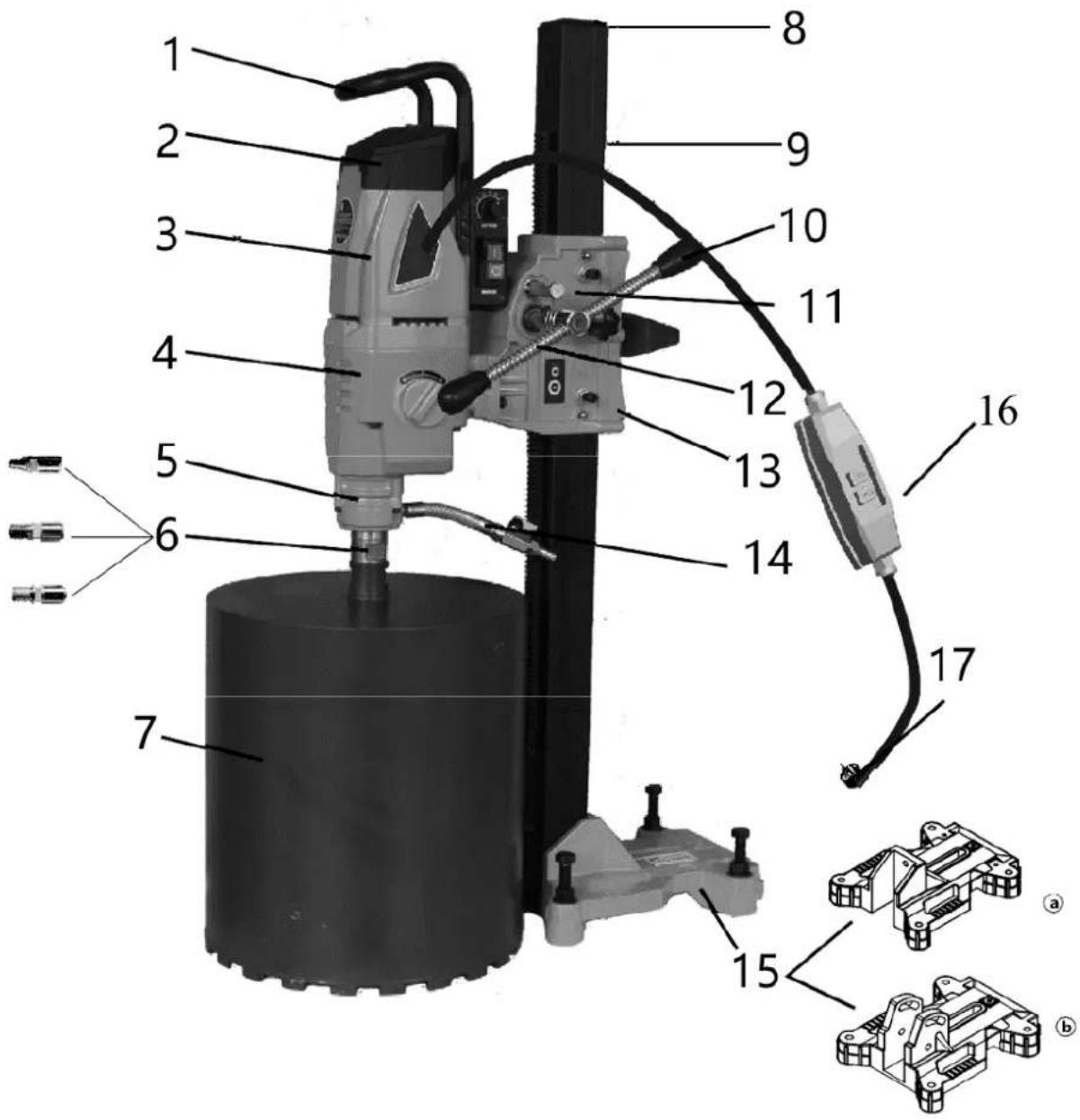
PRODUCE LVSTRUCTURAL BRIEF INTRODUCTION

- Lifted handle
- Stator shell
-
Water circle
-
Bit
-
Square rod
-
Litre reduce ware
- Litre reduces ware back shroud
- Base (a: ordinary; b: tape angle)
-
Power cord
-
Top cover
- Gear case
- Main Shaft (a: Metric; b: Thick tooth; c: Square tooth; d: Britain makes tooth)
- Intermediate cover
- Bakelite ball handle
- Rocker
- Tap
- The protector of leakage of electricity
TECHNICAL CHARACTERISTIC DESCRIBES
Above series drilling machine can only install on frame to use. This machine applies to the professional personage operating use that has gotten professional training, carries out drill hole on the materials such as rock, reinforced concrete and pitch material or take core. The diameter of drill hole exceeds 250 mm, must use high performance expansion bolt to fix. In getting into the process of cutting, cooling water flows through ball valve to go through bit, rushes to go to broken bits, is going to at the same time cool for the knife head of bit( the wet condition that gets into edge.
Diamond bit, it is the pipe form drilling tool of a kind of hollow, when its front the section piece that welding(or sintering) go up and contain diamond If be necessary, cooling water may collect through a kind of special installation (water collector).
SAFE WORKING INSTRUCTION
- Maintain a Clean Working Environment:
Keep your workspace tidy, as clutter can lead to accidents.
- Prepare the Work Area:
Before starting, clean the work environment. Do not use electric tools in the rain or near flammable materials.
- Avoid Electric Shock:
To prevent electric shock, do not touch grounded parts such as metal pipes, heating pipes, stoves, or coal scuttles with your hands.
- Keep Children and Untrained Individuals Away:
Ensure that children and untrained individuals are kept away from the work area and do not handle electric tools.
- Store Tools Safely:
When not in use, store electric tools in a dry place away from children.
- Do Not Overload the Tool:
Use the tool within its specified load range to achieve optimal performance.
- Wear Appropriate Protective Gear:
Avoid loose clothing or jewelry that can get caught in moving parts. Wear ear protection, rubber gloves, and non-slip shoes. If you have long hair, wear a safety helmet.
- Consider Using a Dust Extraction System:
If necessary, connect the machine to a dust extraction system.
- Handle the Power Cord Properly:
Do not use the power cord for purposes other than intended. Do not pull the machine by the cord or unplug it by pulling on the cord.
- Maintain Proper Posture:
Avoid bending or adopting an awkward stance. Ensure you are standing securely and maintain your balance.
- Properly Maintain Your Tool:
Follow the instructions when changing tools. Regularly inspect the tool and its power cord for damage. Keep the handle dry and free of oil.
- Disconnect Power Before Maintenance:
Unplug the tool before performing maintenance or changing bits, especially if the machine will be unused for a long time.
- Ensure No Tools Are Left on the Machine:
Before starting the machine, make sure no tools (like spanners) are left on the bit or work surface.
- Avoid Accidental Start-Up:
When moving the machine or connecting it to a power source, do not place your finger on the switch. Ensure the switch is in the "off" position before plugging in.
- Use Proper Extension Cords for Outdoor Use:
If using the tool outdoors, use an extension cord that meets safety requirements.
- Stay Focused:
Do not use the tool when excessively tired, under the influence of alcohol, or after taking medication.
- Select the Right Bit and Speed:
Choose the appropriate bit for the material and set the machine to the correct speed. If the drill rocks during operation, stop and check the alignment of the bit and spindle to avoid damaging the machine or causing danger.
Installation and Operation Instructions for Diamond Drilling Machine
Important Note: Before beginning any installation, ensure that the main power switch is in the "OFF" position.
Step 1: Inspection
- Unpack and Inspect: Open the package and compare the contents with the container load plan. Inspect the machine and parts for any damage that may have occurred during transportation.
- Voltage Check: Ensure that the voltage at the job site matches the voltage indicated on the machine's nameplate.
- Accessory Check: Verify that all attachments listed in the container load plan are included in the package.
Step 2: Connecting the Power Source
- Compliance with Standards: According to European Union standards EN61029 and IEC1029-2-6, diamond drilling machines used for wet operations must be equipped with a residual current device (RCD) to protect against electrical leakage. Ensure that the power socket is properly grounded.
- RCD Protection: Our product comes equipped with an RCD, which includes protection against electrical leakage and under-voltage release. After plugging in the power source, ensure that the RCD's switch is in the "ON" position.
- Voltage Drop: If a voltage drop occurs, the RCD will automatically disconnect the power. Once the voltage returns to normal, reset the RCD by pressing the "RESET" button. The specified operating current for the RCD is 30mA.
- Water Source: Ensure the water source is clean and free from impurities like grit, which could damage the machine's water seals. The maximum allowable water pressure is 3 BAR.
Step 3: Connecting the Water Source
- Water Inlet Connection: The machine is equipped with a flexible water inlet tube with a "quick joint," making it easy to connect to a wire-reinforced suction hose in the water supply system.
Step 4: Safety Testing
- Initial Testing: Press the generator switch and the machine's soft start switch to ensure smooth operation.
- RCD Testing: Press the "TEST" button on the RCD. The machine should stop operating, indicating that the RCD is functioning properly. After the test, restore power to the machine by pressing the "RESET" button on the RCD.
- Water Safety: Never submerge the RCD in water. Regularly test the RCD by pressing the "TEST" button to ensure it is functioning correctly.
Final Note: If the RCD does not function properly, do not use the machine. Operators should not operate the diamond drilling machine without a functioning RCD.
Steps for Using the Diamond Drilling Machine
1. Choose a Suitable Diamond Bit
- Select the Right Bit: Our company's main shaft supports four commonly used types of bits. Choose a high-quality diamond bit that is sharp and suitable for the task.
- Ensure Clearance: Ensure that the diamond bit has enough clearance between the thickness of the bit head and the tube wall, which helps with bit alignment. The bit should have a backlash (clearance) that is larger than the tube wall thickness to ensure smooth operation.
- Bit Preparation: Apply waterproof oil paint to the bit to facilitate easier bit removal later. Ensure that the bit's radial runout (eccentricity) does not exceed 1 mm.
2. Secure the Frame
- Fixing Methods: Common methods to fix the frame include using expansion bolts, vacuum suction, or regular supports.
○ Expansion Bolts: The most common method is using expansion bolts. Ensure the diameter of the metal expansion bolt and the bolt itself is at least 12 mm.
o Vacuum Suction: If using vacuum suction, ensure that the vacuum pump is efficient and that the sealing ring is intact and undamaged.
o Support Stands: When using support stands, ensure that the frame is stable.
• Frame Alignment: If using expansion screws:
- Ensure the surface and the base of the machine are level. If the base is not level, use the spanner included with the machine to adjust the four adjustment screws on the base until it is balanced.
○ After fixing the machine, make sure the generator does not slide on the rack. Pull and move the pillar to ensure it does not sway or move when using the machine.
- Recommendation: We strongly recommend using expansion bolts for securing the frame. Position the expansion screws as close to the pillar as possible for optimal stability. The company is not liable for any issues resulting from improper securing of the machine.
3. Begin Drilling
- Qualified Operation: This rig should only be operated by trained professionals. It is suitable for drilling holes in materials like rock, reinforced concrete, and asphalt, or for core drilling. Always follow the operation instructions carefully.
- Water Supply: Ensure adequate water is supplied through the ball valve to thoroughly flush away debris. If the machine is filling with a mud-water mixture, it indicates insufficient water supply.
- Feed Pressure: Apply the appropriate feed pressure as required. Insufficient pressure may cause the diamond tip of the bit to wear down, significantly reducing drilling efficiency. Occasionally, the bit may require additional adjustments when cutting harder materials like SIC (silicon carbide) to prevent vibration and ensure the diamond remains intact.
- Metal Cutting: When encountering metal, switch to a lower speed and increase the feed pressure.
Obstruction: If the bit becomes stuck, do not force the machine to continue. Immediately stop the machine and use a spanner to carefully loosen the bit before resuming drilling.
- Vertical Drilling: When drilling upwards, use a special water collection basin to prevent water from entering the generator. If the machine stops unexpectedly, restart it only after ensuring that the bit can turn freely and is not obstructed in the hole
FRICTION CLUTCH
The clutch is designed to provide protection for the operator, machine, and bit under high-strength mechanical overload conditions. However, to prevent damage, ensure that the clutch remains in a disengaged state for no more than 3-4 seconds when under load. Prolonged disengagement can cause a rapid increase in temperature, leading to wear on the friction plates.
MASTER SWITCH AND OVERLOAD PROTECTIVE DEVICE
- After pressing the switch, the machine (soft start switch) will start smoothly. If the machine becomes overloaded, the electronic protection switch will alert the operator to the overload with noticeable fluctuations. If the load is not reduced, the switch will automatically shut off after a few seconds. Once the load is removed, the machine can be restarted, and it will again start smoothly.
- Before restarting, ensure that the bit can turn freely and is not blocked in the drill hole. If the machine is subjected to a voltage higher than 260V, it can cause severe damage, potentially burning out the generator. When using a generator to supply power, make sure that the voltage peak does not exceed 260V.
GEAR SPEED ADJUSTMENT
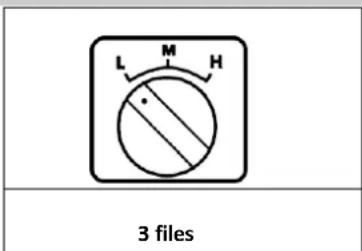
To improve the efficiency of drilling, machines have 3 types of gear speed changes. In it is high to divide, high speed files (H) apply to little bit and more soft material to rush, fast files (M) apply to in bit and more hard material; The files of low speed (L) apply to big bit and hard material.
To improve drilling efficiency, machines feature a three-speed gear system:
• High Speed (H Gear): Suitable for small bits and softer materials.
• Medium Speed (M Gear): Ideal for mid-sized bits and harder materials.
- Low Speed (L Gear): Best for large bits and very hard materials.
Gear Shifting Instructions:
- Shifting Gears: Always shift gears when the machine is stopped or nearly stopped.
- Proper Gear Engagement: When shifting, ensure the gear is fully engaged. If, after starting the machine, the main shaft does not rotate or you hear a grinding noise, it indicates that the gear did not fully engage. Immediately turn off the machine, and while turning the main shaft back and forth, move the gear knob to the desired position until the gear engages properly.
- During Operation: Never attempt to change gears while the machine is running at full speed, under load, or if the bit is jammed. Always stop the machine before shifting gears to avoid damage.
This process helps ensure the gear is correctly engaged and prevents damage to the machine.
COMMON FAULT AND THE METHOD OF REMOVING
| Fault | Reason | Method of Removal |
| Generator does not turn | Power source is obstructed, or contacts are loose | Restore power source, inspect all connections, and tighten them |
| Carbon brush is blocked or disconnected from the commutator | Install a new carbon brush | |
| Leakage protector has tripped and not reset | Press the reset button to restart the generator | |
| Leakage protector is damaged | Replace the leakage protector | |
| Drill hole is too slow | Bit has reached the end of its life | Replace the bit |
| Feed pressure is too low | Increase feed pressure | |
| Bit surface is clogged with debris | Clean the bit and increase hydraulic pressure | |
| Rotational speed is too high | Shift to a lower speed setting | |
| Cutting through thick reinforcing bar causes slippage | Reduce feed pressure slightly, then increase pressure after passing through | |
| Debris accumulates at the bottom of the hole | Clear debris from the hole bottom and apply more pressure | |
| Water flow is obstructed, or there is no return flow | Check the water valve and inspect water flow | |
| Bit has lost sharpness | Re-sharpen the bit using fire-resistant brick or emery wheel | |
| Bit blocks | Debris or broken reinforcing bar pieces are stuck between the bit and the hole wall, or the frame is not securely fixed | Stop the machine, use a spanner to turn or remove the bit, clear the obstruction, and adjust the sliding sleeve gap |
| Bit wall wears rapidly | Main shaft is misaligned | Repair or replace the main shaft |
| Bit is misaligned | Replace the bit | |
| Reinforcing bar or debris cannot be removed from the hole | Improve water flow, remove the bit, and clean the hole | |
| Water set leakage | Skeleton sealing ring is worn or aged | Replace the skeleton sealing ring |
MAINTENANCE
Maintenance Instructions
Important Note: Before performing any maintenance on the machine, always disconnect the power source by unplugging the machine.
1. Cleaning the Machine:
- Use a rag to clean the machine. Do not use water to spray or wash the machine.
- Ensure that water does not enter the generator or switch box.
- Keep the air-breather clean and unblocked.
- Clean the main shaft and apply oil to it.
2. Lubricating the Gear:
- After 300 hours of operation, the gear lubricating oil should be changed by a professional following these steps:
- Ensure the machine is fixed vertically (with the main shaft facing down).
- Loosen the 36 angle screws on the gear case shell and remove the generator and intermediate cover.
- Replace the gear lubricating oil with the brand specified by the manufacturer.
- Reassemble the machine in the correct order and ensure everything is properly installed.
- Caution: If you notice any lubricating oil leakage, immediately stop using the machine to prevent damage to the gears.
3. Water Set Sealing Ring:
- If cooling water leaks from the water set, replace the sealing ring immediately. This task should be performed by a professional at an authorized repair station.
4. Carbon Brush:
- After 300 hours of operation, inspect the carbon brush to determine if it needs replacement.
- All maintenance related to the generator should be carried out by a professional.
Following these maintenance steps will help ensure the machine continues to operate efficiently and safely.

NAJCZĘSTSZE USTERKI I SPOSÓB ICH USUWANIA
PRODUIRE LVSTRUCTUREL BRÈVE INTRODUCTION

PRODUCEER LVSTRUCTURELE KORTE INLEIDING

- Løftet håndtak
- Stator skall
-
Vannsirkel
-
Bit
-
Firkantet stang
-
Liter redusere varer
- Liter reduserer bakdekselet
- Base (a: vanlig; b: tapevinkel)
-
Strømkabel
-
∅vre deksel
- Girkasse
- Hovedaksel (a: metrisk; b: tykk tann; c: firkantet tann; d: Storbritannia lager tann)
- Mellomdeksel
- Bakelitt kulehåndtak
- Rocker
- Tappekran
- Beskytteren mot lekkasje av elektrisitet
TEKNISKE EGENSKAPER BESKRIVER
- Podignuta ručka
- Ljuska statora
- Vodeni krug
- bit
- Četvrtasta šipka
- Litarsko smanjivanje posuđa
- Litar smanjuje stražnji pokrov posuđa
- Baza (a: obična; b: kut trake)
-
Kabel za napajanje
-
Gornji poklopac
- Mjenjač brzine
- Glavna osovina (a: Metrička; b: Debeli zub; c: Četvrtasti zub; d: Britanija pravi zub)
- Srednji poklopac
- Kuglična drška od bakelita
- Rocker
- Dodirnite
- Zaštita od curenja električne energije
TEHNIČKE KARAKTERISTIKE OPIS
Stroj za bušenje iznad serije može se instalirati samo na okvir za korištenje. Ovaj stroj se odnosi na profesionalne osobe koje su stekle profesionalnu obuku, buše rupe na materijalima kao što su stijene, armirani beton i smolni materijal ili uzimaju jezgru. Promjer izbušene rupe premašuje 250 mm, za pričvršćivanje morate koristiti ekspanzione vijke visoke učinkovitosti. Ulaskom u proces rezanja, voda za hlađenje teče kroz kuglasti ventil kako bi prošla kroz svrdlo, juri do slomljenih bitova, istovremeno će se ohladiti za glavu noža (mokro stanje koje ulazi u rub.
Dijamantno svrdlo, to je alat za bušenje u obliku cijevi neke vrste šupljine, kada se njegov prednji dio zavarivanjem (ili sinteriranjem) podiže i sadrži dijamant Ako je potrebno, voda za hlađenje može se skupljati kroz neku vrstu posebne instalacije (kolektor vode).
UPUTE ZA SIGURAN RAD
- Održavajte čisto radno okruženje :
Držite svoj radni prostor urednim, jer nered može dovesti do nezgoda.
- Pripremite radni prostor :
Prije početka, očistite radno okruženje. Nemojte koristiti električne alate na kiši ili u blizini zapaljivih materijala.
- Izbjegnite električni udar :
Kako biste spriječili strujni udar, ne dirajte rukama uzemljene dijelove poput metalnih cijevi, cijevi za grijanje, peći ili posude za ugljen.
- Držite djecu i neobučene osobe podalje:
Osigurajte da se djeca i neobučene osobe drže podalje od radnog područja i da ne rukuju električnim alatima.
PRODUCE LVSTRUCTURAL SCURT INTRODUCERE
For the disposal of the device please consider and act according to the national and local rules and regulations.
CONTACT
expondo Polska sp. z o.o. sp. k.