Cama - Stroller Lionelo - Free user manual and instructions
Find the device manual for free Cama Lionelo in PDF.

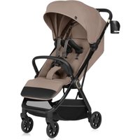
| Product type | Double stroller convertible to bike trailer |
| Brand | Lionelo |
| Model | Cama |
| Usage | Stroller for children up to 22 kg (approx. 4 years) and bike trailer for two children (max 22 kg each) |
| Load capacity | Maximum total load (children + luggage): 45 kg; rear basket: 5 kg |
| Weight | Approximately 14 kg (estimate) |
| Dimensions (unfolded) | Approximately 100 x 65 x 100 cm (estimate) |
| Materials | Steel frame, fabric covering |
| Wheels | Front wheel mountable/removable, rear wheels with quick-release button; inflatable tires (pressure 35-40 PSI) |
| Suspension | Adjustable SIQ suspension (Low/High) under the frame |
| Safety | Parking brake, 5-point safety harnesses, warning flag, reflectors on wheel guards, multiple locks |
| Compliance | Suitable for children weighing up to 22 kg or up to 4 years (whichever occurs first) |
| Care and cleaning | Clean the frame with a damp cloth and mild detergent; Dri-Seat insert machine washable at 30°C; lubricate wheels with bike chain lubricant |
| Included accessories | Tongue, bike attachment system (x2), warning flag, wheel guards with reflectors, tether, seats with 5-point harnesses (x2) |
| Repairability | Spare parts provided or recommended by the manufacturer; contact: help@lionelo.com |
| Warranty | See website for detailed conditions |
Frequently Asked Questions - Cama Lionelo
User questions about Cama Lionelo
0 question about this device. Answer the ones you know or ask your own.
Ask a new question about this device
Download the instructions for your Stroller in PDF format for free! Find your manual Cama - Lionelo and take your electronic device back in hand. On this page are published all the documents necessary for the use of your device. Cama by Lionelo.
USER MANUAL Cama Lionelo
natural_image
Line drawing of a lionelo push cart with wheels and handle (no text or symbols on the device itself)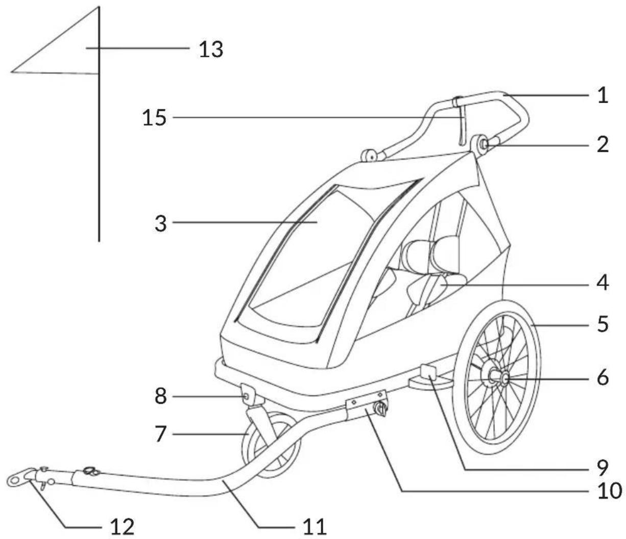
natural_image
Technical line drawing of a car's rear wheel assembly with labeled component '14' (no text or symbols beyond label)
natural_image
Line drawing of a car front view showing steering wheel, dashboard, and seat (no text or symbols)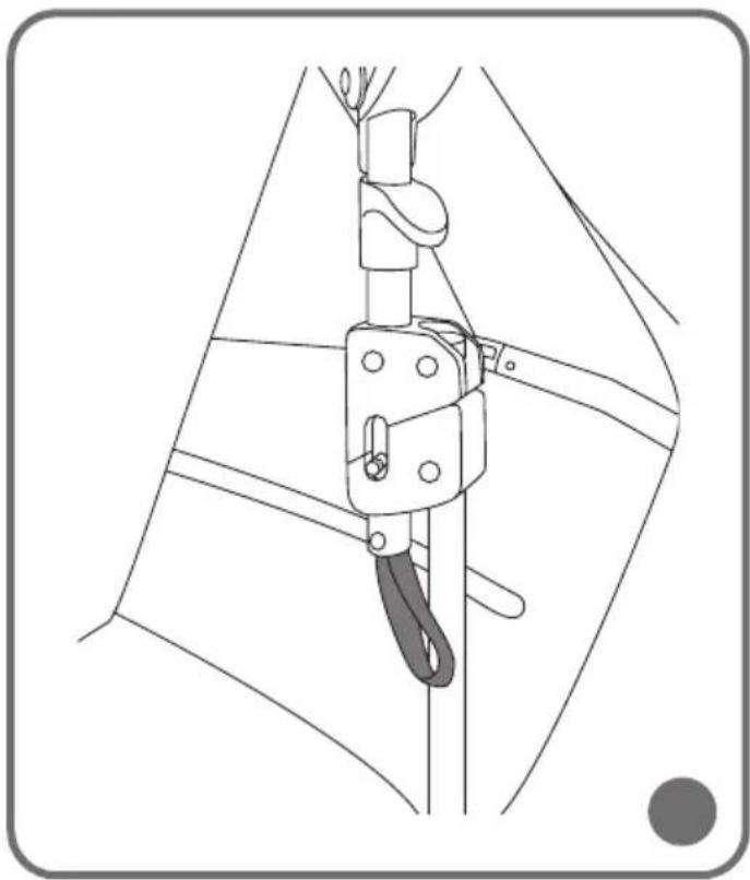
natural_image
Technical line drawing of a mechanical clamp or lifting device (no text or symbols)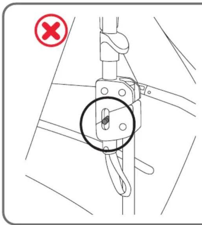
natural_image
Technical line drawing of a mechanical clamp or bracket assembly (no text or symbols)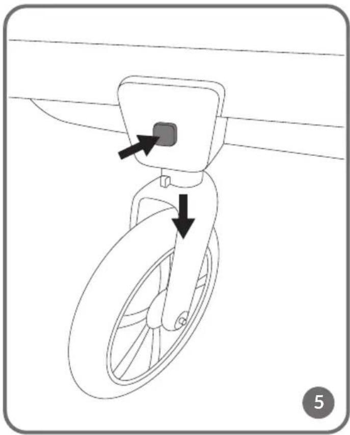
natural_image
Diagram of a bicycle wheel with a small component inserted, showing two arrows indicating direction (no text or symbols present)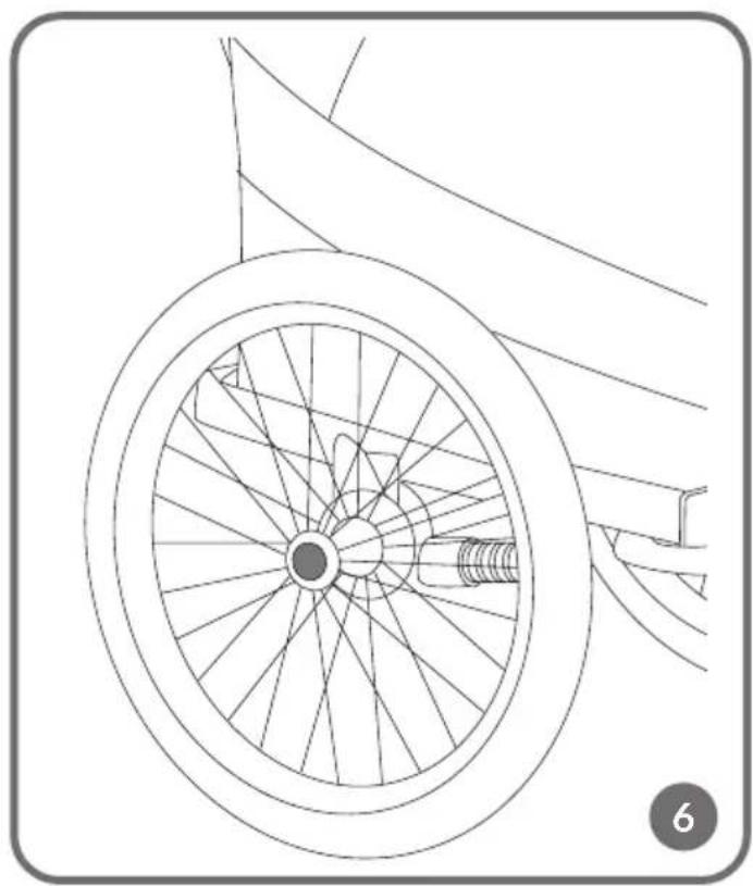
natural_image
Line drawing of a bicycle wheel with spokes and a wheel rim, no text or symbols present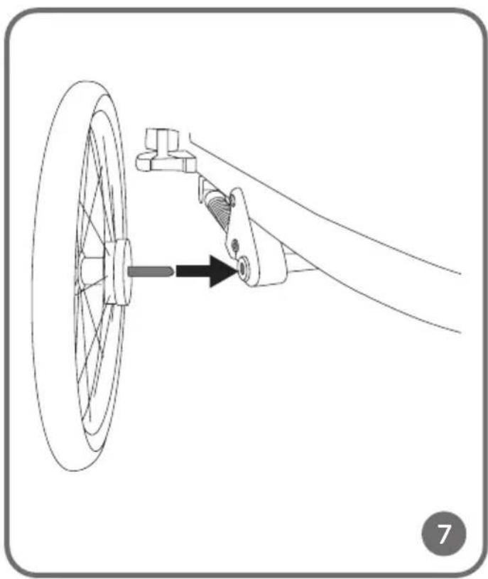
natural_image
Diagram of a bicycle wheel assembly with a connecting rod and bracket, showing motion direction (no text or symbols)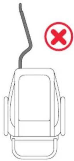
natural_image
Simple line drawing of a car interior with a smoke trail and a red X symbol (no text or labels)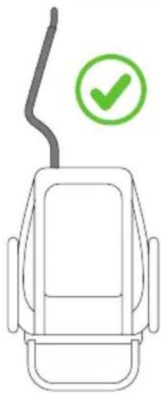
natural_image
Simple line drawing of a car's front view with a green checkmark indicating the correct inspection (no text or symbols present)8
natural_image
Diagram of a mechanical linkage or mounting bracket with a lever and base, showing no text or symbols.9
natural_image
Technical line drawing of a mechanical device with wheels and mounting bracket (no text or symbols)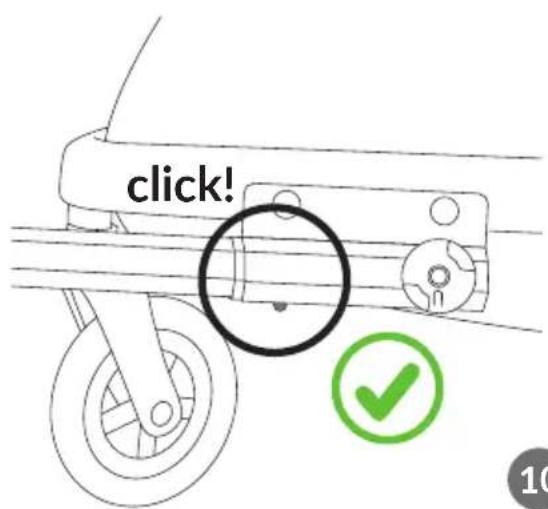
10
natural_image
Technical diagram showing a mechanical assembly with a bracket and a lock, no text or symbols present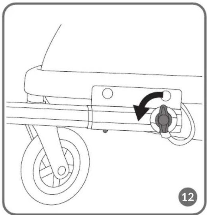
natural_image
Line drawing of a bicycle's wheel and suspension mechanism with directional arrow (no text or symbols)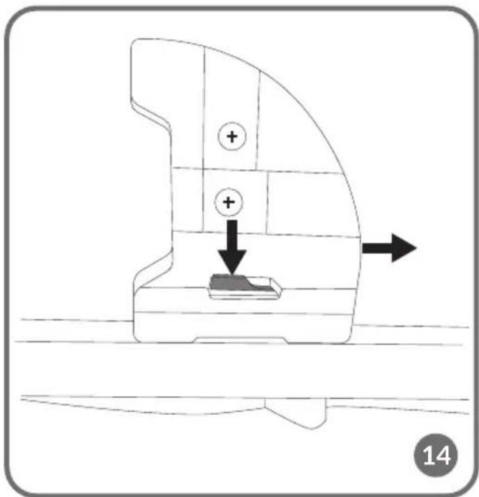
natural_image
Technical line drawing showing two mechanical assembly steps with arrows indicating motion direction (no text or symbols)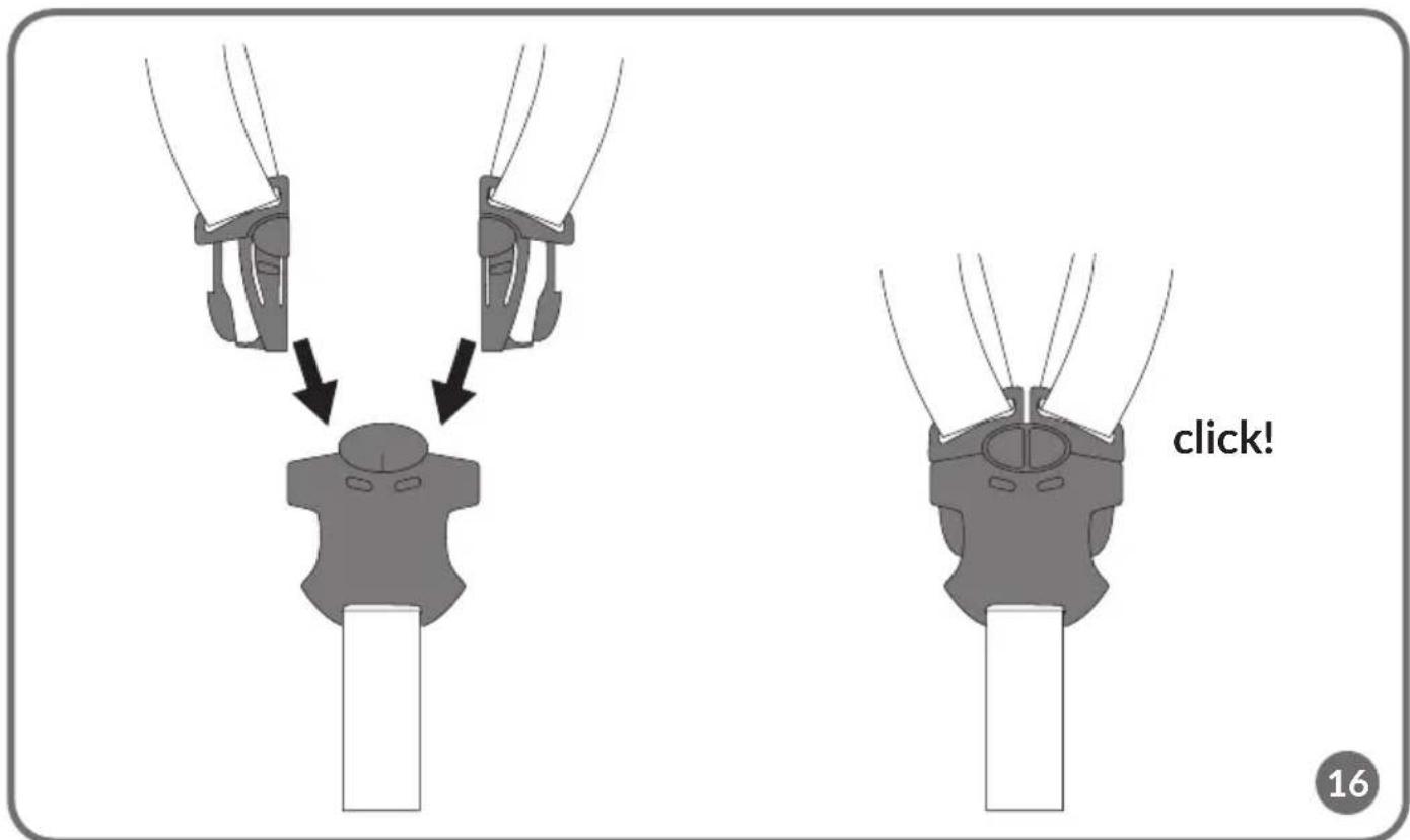
natural_image
Diagram showing two mechanical assembly steps with arrows indicating movement, no text or symbols present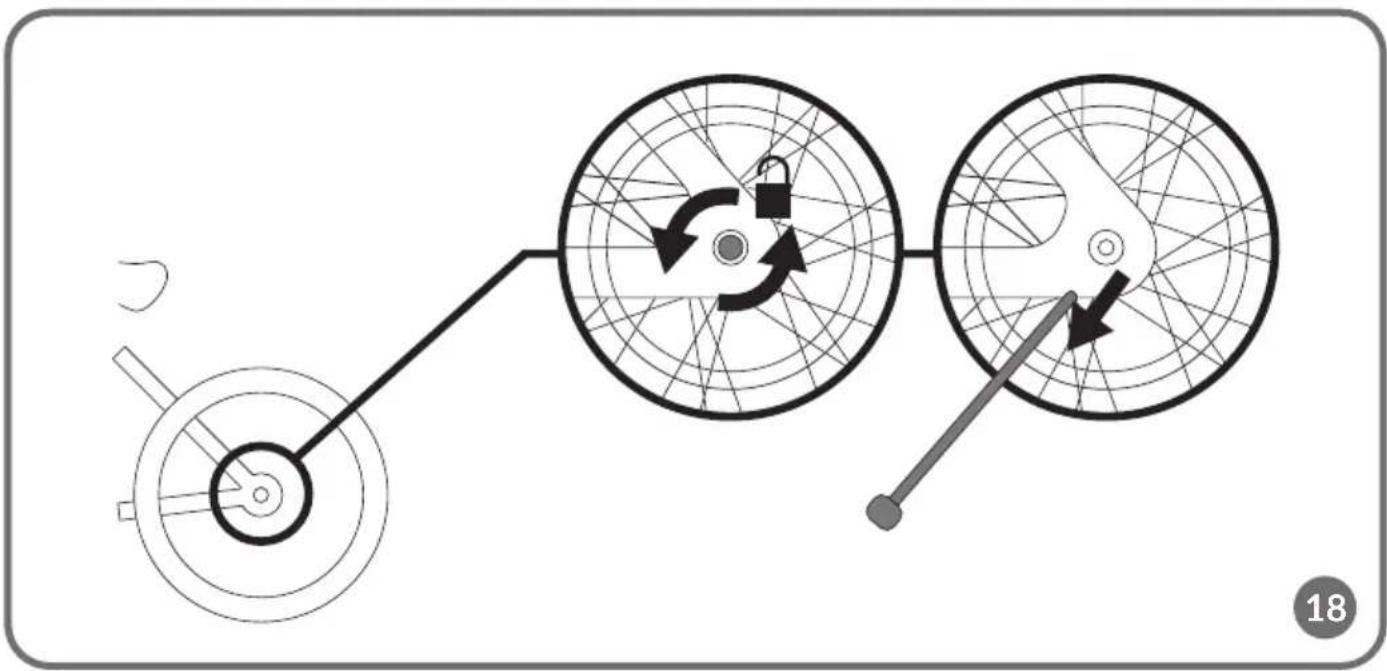
flowchart
graph TD
    A["Terminal Block"] --> B["Component 1"]
    B --> C["Component 2"]
    C --> D["Component 3"]
    D --> E["Terminal Block"]
natural_image
Two mechanical components with directional arrows indicating motion, no text or symbols present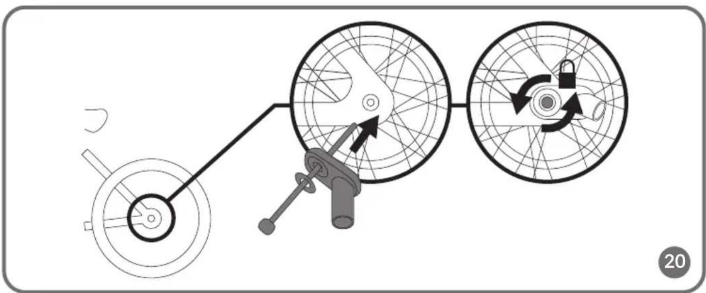
flowchart
graph TD
    A["Main Component"] --> B["Valve with Switch"]
    B --> C["Lock Mechanism"]
    C --> D["Circular Component with Switch"]
    style A fill:#f9f,stroke:#333
    style B fill:#ccf,stroke:#333
    style C fill:#cfc,stroke:#333
    style D fill:#fcc,stroke:#333
natural_image
Diagram of a bicycle steering wheel assembly with close-ups of mechanical components (no text or labels)
natural_image
Line drawing of a car with a person wearing a helmet and a curved pipe, no text or symbols present
natural_image
Line drawing of a vehicle with a person inside the cab and a curved pipe extending outward (no text or symbols)

natural_image
Diagram of a vehicle with two workers inside, showing wheel rim and cable (no text or symbols)
natural_image
Illustration of a vehicle with two workers inside, viewed from the side (no text or symbols)23
natural_image
Mechanical assembly diagram showing a spring-loaded component with motion arrows (no text or symbols)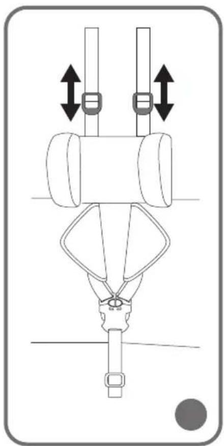
natural_image
Diagram of a mechanical device with two vertical bars and bidirectional arrows indicating motion or force directions (no text or symbols)Dear Customer!
If you have any comments or questions about the product you have purchased, please contact us:
help@lionelo.com
Manufacturer:
BrandLine Group Sp. z o.o.
IMPORTANT! READ CAREFULLY AND KEEP FOR FUTURE REFERENCE
WARNING!
- Never leave the child unattended.
- Ensure that all the locking devices are engaged before use.
- To avoid injury ensure that the child is kept away when unfolding and folding this product.
- Do not let the child play with this product.
- This seat unit is not suitable for children under 6 months.
- Always use the restraint system.
- Check that the pram body or seat unit or car seat attachment devices are correctly engaged before use.
- This product is not suitable for running or skating.
- The product is suitable for a child weighing up to 22 kg or up to 4 years (whichever comes first).
- If you want to take the baby out of the stroller, or put it in it, make sure the locking mechanism is locked.
- The maximum load on the luggage space behind the seat is 5 kg, but the sum of the weight of children and luggage must not exceed 45 kg.
- Any load attached to the handle and / or the back of the backrest and / or the sides of the product will affect the stability of the stroller.
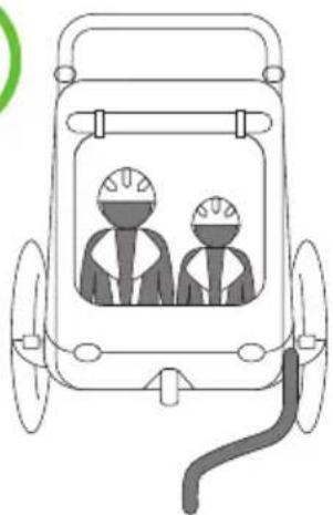
- The product can be used by two children at the same time.
- Do not use accessories that have not been approved by the manufacturer.
- Use only spare parts supplied or recommended by the manufacturer.
- Do not use the product on stairs.
WARNINGS FOR THE BICYCLE TRAILER
- Make sure, based on information from the bicycle manufacturer, that the bicycle is suitable for use with a bicycle trailer. Use the trailer only with a suitable bicycle.
- The trailer can be used to carry a maximum of two children. It is recommended to
use the trailer on as level ground as possible, with little traffic and in daylight.
- The seat is designed for two children, each weighing a maximum of 22 kg, and with a maximum height of 116.5 cm.
- A 5-point seat belt should always be used.
- The allowable nominal weight (passengers and load) is 45 kg.
- The minimum allowable drawbar load is from 3 kg, the maximum - 8 kg.
- Follow the instructions for proper installation of the trailer. Read this instruction manual before using the trailer and follow its recommendations.
- Improper use and failure to follow safety instructions can lead to serious injury to people being transported.
- Always observe local regulations and national traffic requirements.
- When using the trailer in low-light conditions, (e.g., dusk, night) or with limited visibility, make sure the product is properly illuminated and marked. Local lighting regulations should be observed. The lighting set should be attached to the product frame and be visible from the front and rear. Consult your point of sale or authorized bicycle service center to select a suitable lighting set that meets local lighting regulations.
- Regularly check the safety condition of components such as the drawbar, connections, frame, belts, lights, tires and wheels. Check that bolts are properly tightened.
- Once the trailer is attached to the bicycle, the distance needed to stop and the ability to make turns are affected. Avoid sudden maneuvers and avoiding obstacles, be cautious on steep sections and turns.
- Be aware that the trailer can adversely affect the braking efficiency of the bicycle.
- The trailer cover must be closed when in use to protect children while riding.
- Children are required to use protective helmets at all times while riding.
- Check the air pressure in the tires. The pressure should be between 35 and 40 PSI.
- Do not turn violently, due to the risk of the trailer tipping over.
- Do not move at high speed.
- Do not exceed 25 km/h, slow down on turns and in difficult road conditions. High speed negatively affects the ability to control the bicycle.
- The maximum speed when turning and on rough roads is 8 km/h.
- Never use the trailer off-road. It is designed for use on paved roads. Using it off-road may cause damage to the trailer or injury to passengers.
- Never use the trailer to transport children together with animals.
- Bicycle trailers used with electric bicycles (EPAC) may be restricted by law.
- Always use a warning flag when using the product as a bicycle trailer.
DRAWBAR LOAD
To test the pressure that the drawbar exerts in a loaded trailer, do the following (A or B).
A. Place the drawbar at a height of about 25 cm and measure the load by applying a luggage scale to the end with the mounting system.
B. Place the drawbar on a bathroom scale set at a height of about 25 cm.
Note! The load should be between 3 and 8 kg.
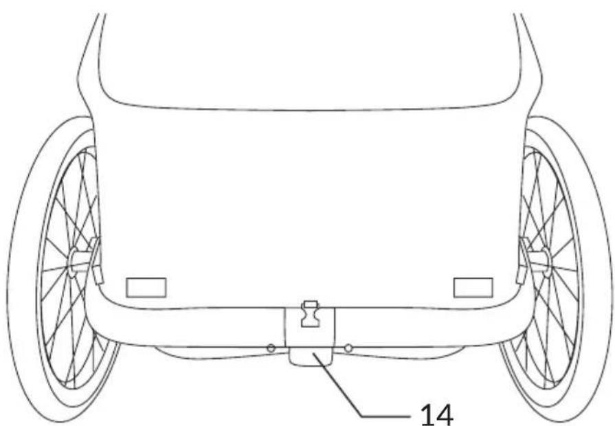
LIST OF PARTS (FIG. A)
- Holder for the caretaker
- Adjustment button for caregiver handle
- Front cover
- Seat with 5-point seat belts (x2)
- Rear wheel
- Rear wheel installation/removal button
- Front wheel
-
Front wheel removal button
-
Wheel cover with reflector (x2)
- Drawbar socket
- Drawbar
- Bicycle mounting system (x2)
- Warning flag
- Locking mechanism lever
- Wrist strap
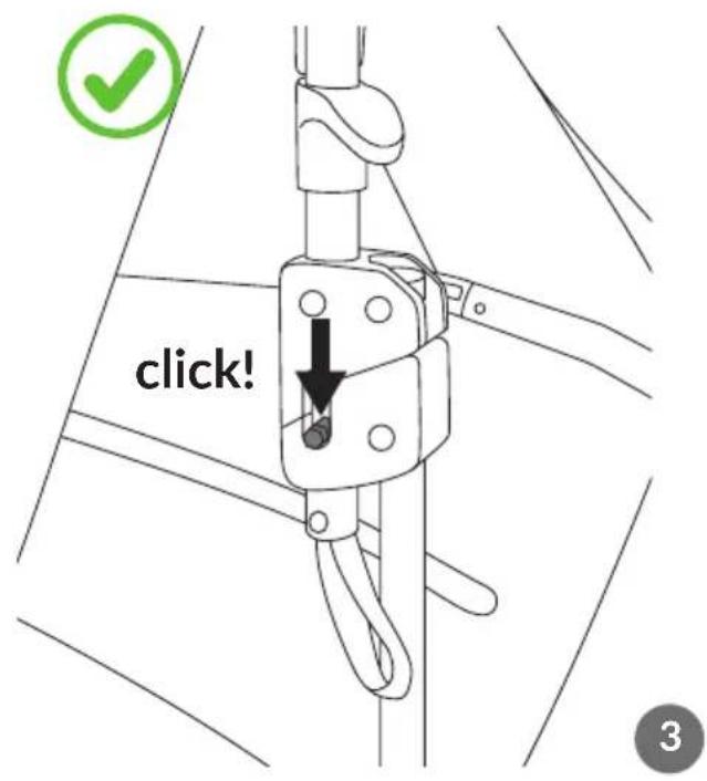
UNFOLDING THE FRAME
To open the trailer frame, lift the caretaker's handle (1, fig. A) upward, and then unfold the seat frame (fig. 1). Next, make sure that the latches on both sides of the frame are locked by pulling on the straps (fig. 2). The correct locking of the latches will be signaled by a click (fig. 3).
Note! Make sure that the locking mechanism is in place (fig. 3).
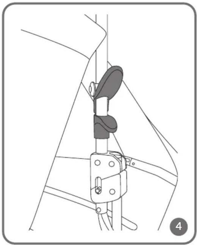
FOLDING THE FRAME
To fold the frame, press both handles on the right and left sides of the frame at the same time (fig. 4), then gently push the frame down.
INSTALLATION AND REMOVAL OF THE FRONT WHEEL
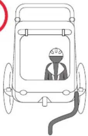
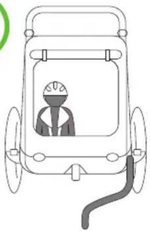
Note! The front wheel can only be installed when the product is used in the function of a stroller. When using the product in the function of a trailer, always make sure that the front wheel is removed.
To install the front wheel, insert the wheel stem into the appropriate hole in the frame. The wheel will lock automatically, and proper installation will be signaled by a click. Pull gently on the wheel to make sure it is locked. To remove the front wheel, press the button above the wheel (fig. 5), and then pull the wheel out of the socket.
INSTALLATION AND REMOVAL OF REAR WHEELS
To install the rear wheels, press the button located in the center of the wheel (fig. 6), and then insert the wheel stem into the corresponding hole in the frame (fig. 7). The wheels will lock automatically. Pull gently on both wheels to make sure they are locked.
To remove the rear wheels, press the button located in the center of the wheel (fig. 6), and then pull the wheels out of the socket.
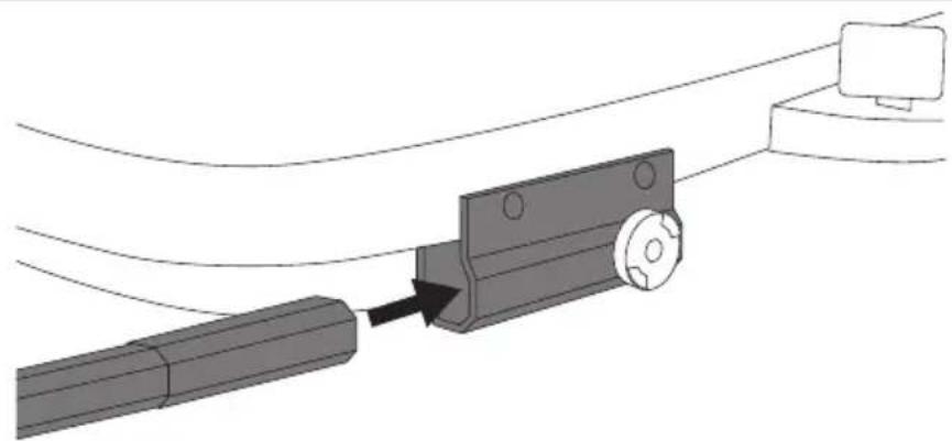
INSTALLATION AND REMOVAL OF THE DRAWBAR
- Slide the drawbar in the correct position (fig. 8) into the socket on the trailer frame (fig. 9).
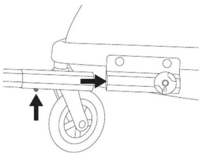
- Push in the safety feature (fig. 10) and, holding it, slowly slide the drawbar into the hole.
- Make sure that the safety feature (fig. 10) is in place and the drawbar is stable and locked. Correct installation will signal a click.
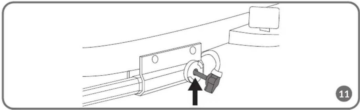
- Slightly lift the front of the product by grasping the drawbar. Slide the lock (fig. 11) into the corresponding hole of the drawbar installation element. Make sure that the lock is fully inserted.
- Turn the protruding nut (fig. 12) counterclockwise. Pull the lock to make sure it is properly installed.
- Pull the drawbar to make sure it is locked before using the product as a bicycle trailer.
For removal, follow the above steps in reverse order.
Note! Check the lock regularly to make sure it has not come loose or opened. Failure to do so could cause serious injury to you or your child.
LOCKING MECHANISM
To activate the locking mechanism, depress the lever located at the rear of the frame (14, fig. A). To stop the locking mechanism, lift the lever.
Note! The locking mechanism must be locked each time children are put in and taken out of the trailer.
INSTALLATION AND REMOVAL OF THE WHEEL COVER WITH REFLECTOR
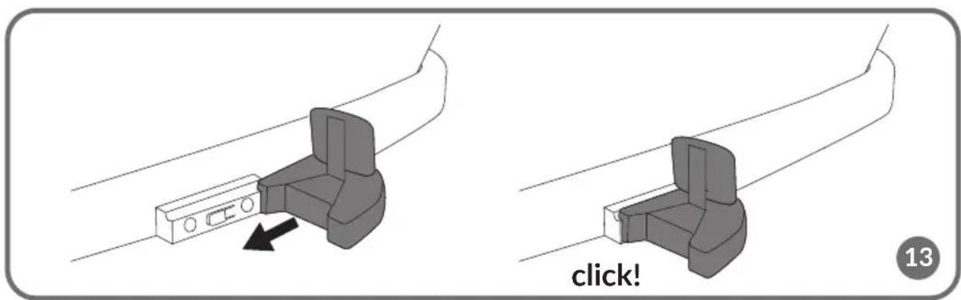
Slide the wheel guard onto the guide located on both sides of the frame (fig. 13). Correct installation will signal a click.
For removal, press the button located inside the cover (fig. 14) and slide it off.
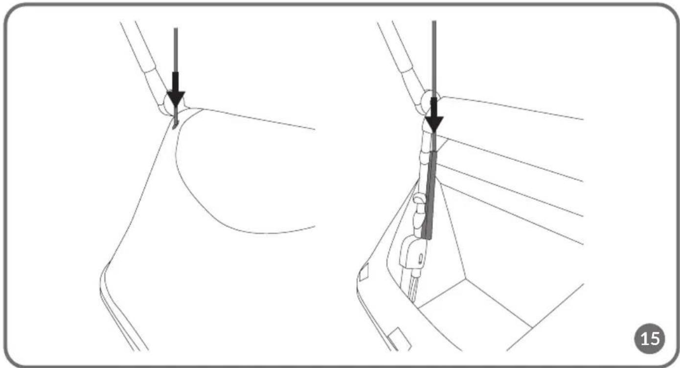
INSTALLATION OF THE WARNING FLAG
Put the flag through the hole in the cover, and then insert it into the tunnel in the fabric of the cover located on the left side of the caretaker's handle (fig. 15).
Note! The flag is a mandatory part of the set.
The flag is intended for use only in the function of a bicycle trailer. The flag is not a toy. Do not let your child play with the flag. Failure to comply with this warning may cause serious injury.
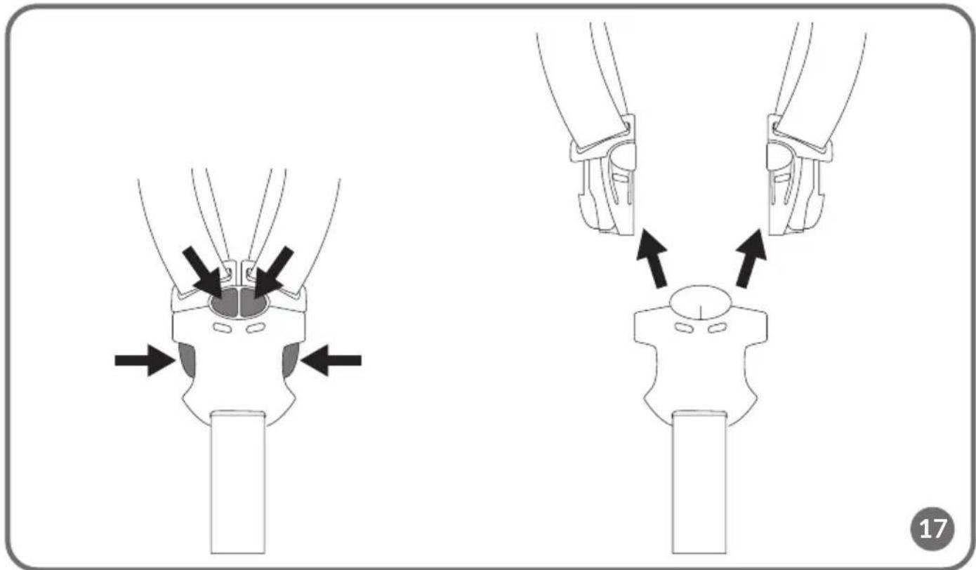
5-POINT SEAT BELTS
Fastening
Slide both latch components into the buckle (fig. 16). Correct fastening will signal a click.
Unfastening
Simultaneously press the red buttons in the center of the buckle and the buttons on the sides of the buckle (fig. 17).
Adjustment
Thread the belts through the buckles to adjust and adapt the length to the child's height (fig. 25).
CAREGIVER HANDLE ADJUSTMENT
Press both handle adjustment buttons (2, fig. A) and select one of the available positions. A 7-position handle adjustment is possible.
INSTALLATION OF THE BICYCLE TRAILER
Always install the drawbar on the left side of the bicycle, looking in the direction of travel.
- Remove the front wheel of the trailer (see: Installation and removal of the front wheel).
- Install the drawbar (see: Installation and removal of the drawbar).
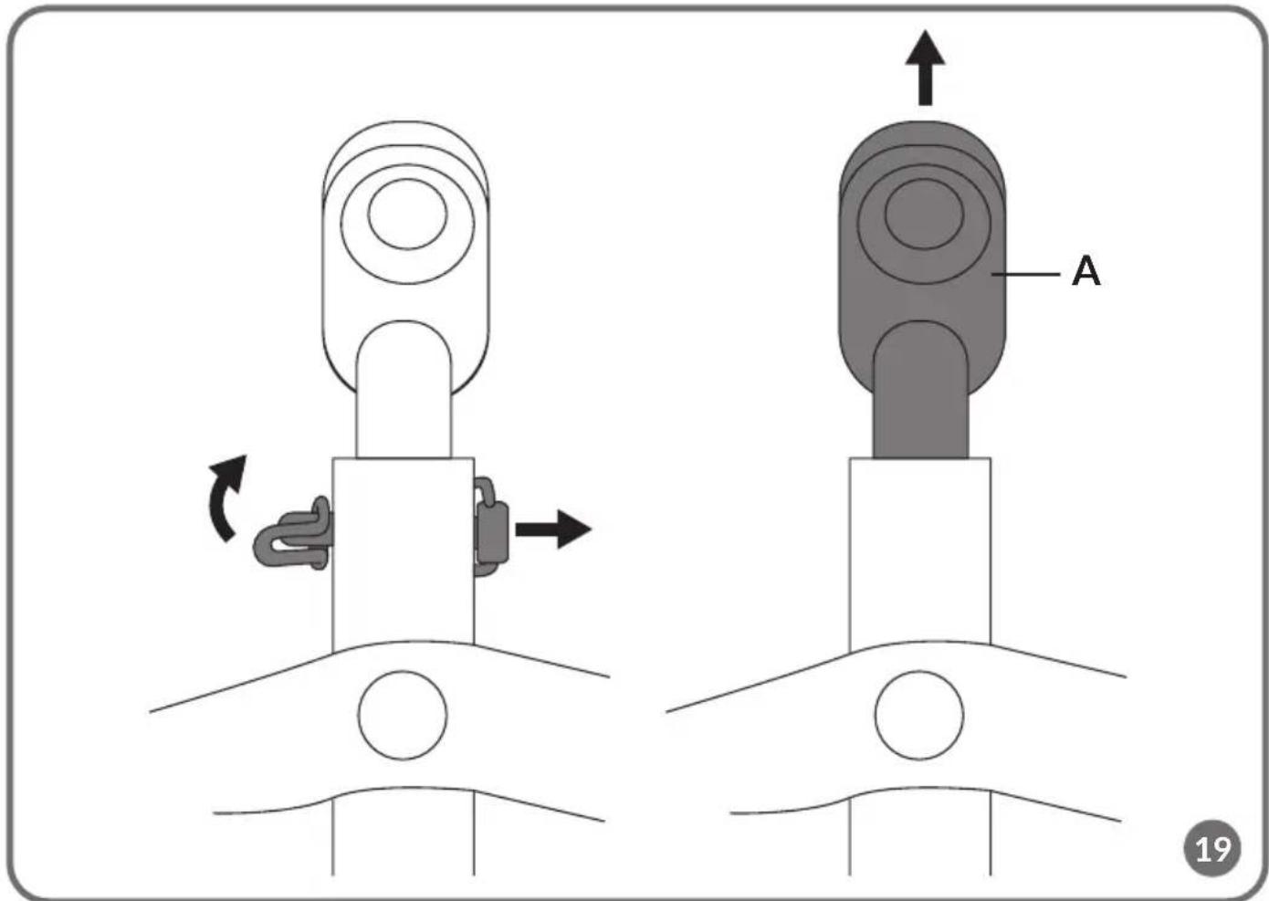
- Unscrew the axle of the rear bicycle wheel (fig. 18). Unbolt the connecting element (A, fig. 19) from the drawbar, and place it in the bicycle rear wheel axle. Screw the axle again (fig. 20).
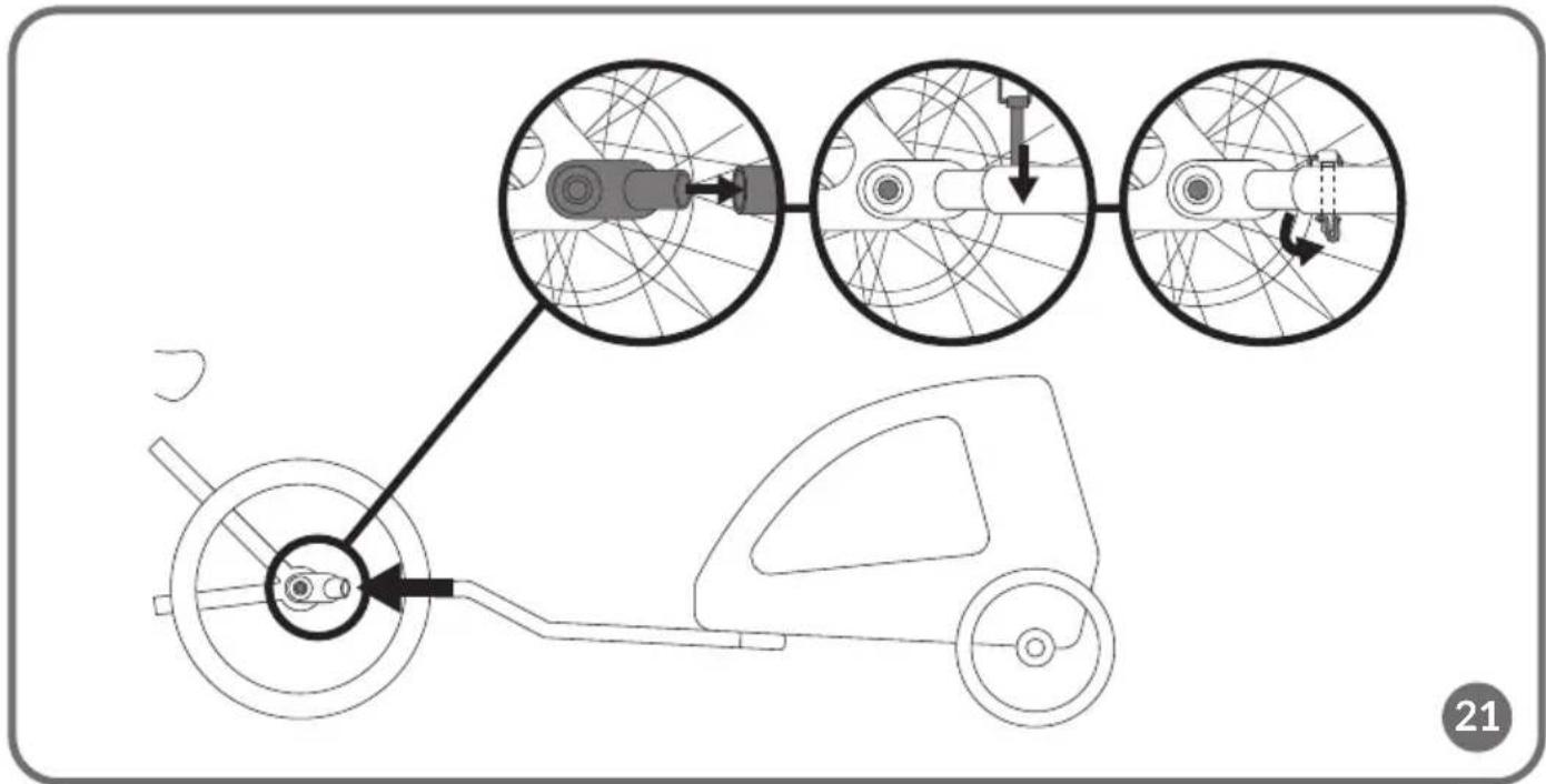
- Connect the drawbar to the connecting element on the bicycle, and then insert the lock into the appropriate hole to secure the fastener (fig. 21).
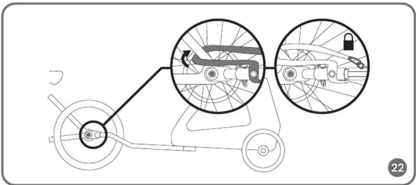
- Put the belt through the bicycle wheel frame and fasten on the drawbar (fig. 22).
Note! When transporting one child, the child must be on the opposite side of the drawbar. When transporting
two children, the child with the higher weight must be on the opposite side of the drawbar (fig. 23).
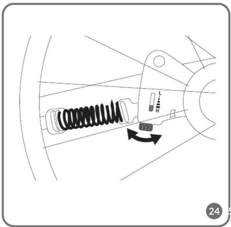
SUSPENSION ADJUSTMENT (SIQ)
SIQ suspension has a significant impact on passenger and cyclist comfort when using the product as a trailer. The control arm-based design offsets the forces acting when negotiating bumps, speed bumps, accelerating or braking.
Adjust the suspension using the knob located under the trailer frame (fig. 24) in the range from L (Low) to H (High).
CLEANING AND MAINTENANCE
In order to ensure the reliability and long-term performance of the product, it is necessary to regularly inspect, maintain and care for its condition. Inspect the trailer regularly, carefully examining the condition of the wheels, frame, cover, drawbars, hitch, seat belts, safety systems and safety pins. Tire pressure should be checked regularly. If any damage is found, it is necessary to remove it immediately before using it again.
The wheels and their components should be cleaned and lubricated regularly. Use lubricants designed for lubricating bicycle chains.
The Dri-Seat pad can be machine washed at 30^ C. To remove the pad, unfasten the belts and put them through the appropriate holes. Then unfasten the hook-and-loop fasteners and remove the pad.
Clean the frame regularly with a damp cloth and mild detergent.
The photos are for reference only, the actual look of the products may differ from the ones shown in the pictures.
PL
Drogi Kliencie!
BrandLine Group Sp. z o.o.
BrandLine Group Sp. z o.o.
BrandLine Group Sp. z o.o.
BrandLine Group Sp. z o.o.
BrandLine Group Sp. z o.o.
BrandLine Group Sp. z o.o.
WAARSCHUWING VOOR FIETSAANHANGER
BrandLine Group Sp. z o.o.
A. Kręglewskiego 1, 61-248 Poznań (Poznanė), Lenkija
JSPĖJIMAI DĖL VAIKIŠKO VEŽIMĖLIO: ŠVARBU! ATIDŽIAI PERSKAITYKITE IR SAUGOKITE, KAD VĖLIAU GALĖTUMĖTE PASISKAITYTI. JSPĖJIMAS!
MONTÁŽ A DEMONTÁŽ ZADNÍCH KOL
MONTÁŽ A DEMONTÁŽ OJE
MONTÁŽ A DEMONTÁŽ KRYTU KOLA S ODRAZKOU
BrandLine Group Sp. z o.o.
BrandLine Group Sp. z o.o.
MONTAREA REMORCII PE BICICLETĂ
BrandLine Group Sp. z o.o.
BrandLine Group Sp. z o.o.
BrandLine Group Sp. z o.o.
A. Kręglewskiego 1, 61-248 Poznań, Puola
VAROITUKSET LASTENVAUNUJA VARTEN TÄRKEÄÄ! LUE HUOLELLISESTI JA SÄILYTÄ VASTAISUUDEN VARALLE VAROITUS!
Detailed warranty conditions are available on the website: