
RC-ICMD15 - Ice machine Royal Catering - Free user manual and instructions
Find the device manual for free RC-ICMD15 Royal Catering in PDF.

User questions about RC-ICMD15 Royal Catering
0 question about this device. Answer the ones you know or ask your own.
Ask a new question about this device
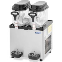
Download the instructions for your Ice machine in PDF format for free! Find your manual RC-ICMD15 - Royal Catering and take your electronic device back in hand. On this page are published all the documents necessary for the use of your device. RC-ICMD15 by Royal Catering.
USER MANUAL RC-ICMD15 Royal Catering
natural_image
Abstract white line drawing of a stylized creature or mythical creature on a dark blue background (no text or symbols)| DE | Produktname | Eismaschine mit Spender 1.5L |
| EN | Product name | Ice Cream Maker and Dispenser with compressor 1.5L |
| PL | Nazwa produktu | Maszyna do lodów z dozownikiem 1.5L |
| CZ | Název výrobku | Výrobník zmrzliny - 1,5 L |
| FR | Nom du produit | Machine glace italienne - 1,5 l |
| IT | Nome del prodotto | Macchina gelato soft - 1,5 L |
| ES | Nombre del producto | Máquina de helados soft - 1,5 L |
| HU | Termék neve | Lágyfagylaltgép - 1,5 L |
| DA | Produktnavn | Softicemaskine - 1,5 l |
| FI | Tuotteen nimi | Pehmiskone - 1,5 L |
| NL | Productnaam | Softijsmachine - 1,5 L |
| NO | Produktnavn | Softismaskin - 1,5 L |
| SE | Produktnamn | Mjukglassmaskin - 1,5 L |
| PT | Nome do produto | Máquina de gelados - 1,5 l |
| SK | Názov produktu | Stroj na zmrzlinu - 1,5 l |
| DE | Modell | RC-ICMD15 |
| EN | Product model | |
| PL | Model produktu | |
| CZ | Model výrobku | |
| FR | Modèle | |
| IT | Modello | |
| ES | Modelo | |
| HU | Modell | |
| DA | Model | |
| FI | Tuotteen malli | |
| NL | Productmodel | |
| NO | Produktmodell | |
| SE | Produktmodell | |
| PT | Modelo do produto | |
| SK | Model | |
| DE | Hersteller | expondo Polska sp. z o.o. sp. k. |
| EN | Manufacturer | |
| PL | Producent | |
| CZ | Výrobce | |
| FR | Fabricant | |
| IT | Produttore | |
| ES | Fabricante | |
| HU | Termelő | |
| DA | Producent | |
| FI | Valmistaja | |
| NL | Producent | |
| NO | Produsent | |
| SE | Tillverkare | |
| PT | Fabricante | |
| SK | Výrobca | |
| DE | Anschrift des Herstellers | ul. Nowy Kisielin – Innowacyjna 7, 66-002 Zielona Góra | Poland, EU |
| EN | Manufacturer Address | |
| PL | Adres producenta | |
| CZ | Adresa výrobce | |
| FR | Adresse du fabricant | |
| IT | Indirizzo del produttore | |
| ES | Dirección del fabricante | |
| HU | A gyártó cime | |
| DA | Producentens adresse | |
| FI | Valmistajan osoite | |
| NL | Adres producent | |
| NO | Produsentens adresse | |
| SE | Tillverkarens adress | |
| PT | Endereço do fabricante | |
| SK | Adresa výrobcu |

natural_image
Pure mechanical assembly diagram without any text, numbers, or symbols①
natural_image
Hand inserting a component into a circular device (no text or symbols visible)②
natural_image
Hand holding a rectangular object with internal components, no visible text or symbols③

natural_image
Technical line drawing of a mechanical clamp or bracket assembly (no text or symbols)④
natural_image
Mechanical switch mechanism diagram showing lever and handle assembly (no text or symbols)⑤
natural_image
Technical line drawing of a toggle switch mechanism (no text or symbols)⑥
natural_image
Mechanical switch mechanism diagram showing lever and nut assembly (no text or symbols)⑦
natural_image
Technical line drawing of a mechanical component with no visible text or symbols⑧
This User Manual has been translated for your convenience using machine translation. Reasonable efforts have been made to provide an accurate translation; however, no automated translation is perfect nor is it intended to replace human translators. The official User Manual is the English version. Any discrepancies or differences created in the translation are not binding and have no legal effect for compliance or enforcement purposes. If any questions arise related to the accuracy of the information contained in the User Manual, please refer to the English version of those contents which is the official version.
Technical data
| Parameter description | Parameter value |
| Product name | ICE CREAM MAKER AND DISPENSER WITH COMPRESSOR 1.5L |
| Model | RC-ICMD15 |
| Rated voltage [V~] / Frequency [Hz] | 230/50 |
| Rated power [W] | 250 |
| Protection class | I |
| Protection rating IP | IPX0 |
| Dimensions [mm] | 280 x 385 x 320 |
| Weight [kg] | 16,7 |
| Type/amount of refrigerant [g] | R600a / 22 |
| Capacity [L] | 1,5 |
| Insulation gas type | Cyclopentane |
1. General description
The user manual is designed to assist in the safe and trouble-free use of the device. The product is designed and manufactured in accordance with strict technical guidelines, using state-of-the-art technologies and components. Additionally, it is produced in compliance with the most stringent quality standards.
DO NOT USE THE DEVICE UNLESS YOU HAVE THOROUGHLY READ AND UNDERSTOOD THIS USER MANUAL.
EN
To increase the product life of the device and to ensure trouble-free operation, use it in accordance with this user manual and regularly perform maintenance tasks. The technical data and specifications in this user manual are up to date. The manufacturer reserves the right to make changes associated with quality improvement. The device is designed to reduce noise emission risks to a minimum, taking into account technological progress and noise reduction opportunities.
Legend

The product satisfies the relevant safety standards.

Read instructions before use.
The product must be recycled.

WARNING! or CAUTION! or REMEMBER! Applicable to the given situation. (general warning sign)
ATTENTION! Electric shock warning!

ATTENTION! Fire hazard - flammable materials!

Only use indoors.

PLEASE NOTE! Drawings in this manual are for illustration purposes only and in some details may differ from the actual product.
2. Usage safety
ATTENTION! Read all safety warnings and all instructions. Failure to follow the warnings and instructions may result in electric shock, fire and/or serious injury or even death.
The terms "device" or "product" are used in the warnings and instructions to refer to ICE CREAM MAKER AND DISPENSER WITH COMPRESSOR 1.5L.
2.1. Electrical safety
a) The plug must fit the socket. Do not modify the plug in any way. Using original plugs and matching sockets reduces the risk of electric shock.
b) Avoid touching earthed elements such as pipes, heaters, boilers and refrigerators. There is an increased risk of electric shock if the earthed device is exposed to rain, comes into direct contact with a wet surface or is operating in a damp environment. Water getting into the device increases the risk of damage to the device and of electric shock.
c) Do not touch the device with wet or damp hands.
d) Use the cable only for its designated use. Never use it to carry the device or to pull the plug out of a socket. Keep the cable away from heat sources, oil, sharp edges or moving parts. Damaged or tangled cables increase the risk of electric shock.
e) If using the device in a damp environment cannot be avoided, a residual current device (RCD) should be applied. The use of an RCD reduces the risk of electric shock.
f) Do not use the device if the power cord is damaged or shows obvious signs of wear. A damaged power cord should be replaced by a qualified electrician or the manufacturer's service centre.
g) To avoid electric shock, do not immerse the cord, plug or device in water or other liquids. Do not use the device on wet surfaces.
h) ATTENTION! DANGER TO LIFE! While cleaning, never immerse the device in water or other liquids.
2.2. Safety in the workplace
a) Make sure the workplace is clean and well lit. A messy or poorly lit workplace may lead to accidents. Try to think ahead, observe what is going on and use common sense when working with the device.
b) If you are unsure about whether the product is operating correctly or if you find damage, please contact the manufacturer's service centre.
c) Only the manufacturer's service centre may make repairs to the product. Do not attempt to make repairs yourself!
d) In case of fire, use a powder or carbon dioxide (CO2) fire extinguisher (one intended for use on live electrical devices) to put it out.
e) Please keep this manual available for future reference. If this device is passed on to a third party, the manual must be passed on with it.
f) Keep packaging elements and small assembly parts in a place not available to children.
2.3. Personal safety
a) Do not use the device when tired, ill or under the influence of alcohol, narcotics or medication which can significantly impair the ability to operate the device.
b) The device is not designed to be handled by persons (including children) with limited mental and sensory functions or persons lacking relevant experience and/or knowledge unless they are supervised by a person responsible for their safety or they have received instruction on how to operate the device.
c) The device can be handled only by physically fit persons who are capable of handling it, properly trained, familiar with this manual and trained within the scope of occupational health and safety.
d) To prevent the device from accidentally switching on, make sure the switch is on the OFF position before connecting to a power source.
e) The device is not a toy. Children must be supervised to ensure that they do not play with the device.
f) Do not put your hands or other items inside the device while it is in use!
2.4. Safe device use
a) Do not overload the device. Use the appropriate tools for the given task. A correctly-selected device will perform the task for which it was designed better and in a safer manner.
b) Do not use the device if the ON/OFF switch does not function properly (does not switch the device on and off). Devices which cannot be switched on and off using the ON/OFF switch are hazardous, should not be operated and must be repaired.
c) Disconnect the device from the power supply before commencement of adjustment, cleaning and maintenance. Such a preventive measure reduces the risk of accidental activation.
d) Device repair or maintenance should be carried out by qualified persons, only using original spare parts. This will ensure safe use.
e) To ensure the operational integrity of the device, do not remove factory-fitted guards and do not loosen any screws.
EN
f) When transporting and handling the device between the warehouse and the destination, observe the occupational health and safety principles for manual transport operations which apply in the country where the device will be used.
g) Avoid situations where the device stops working during use due to excessive loading. This may result in overheating of the drive elements and damage to the device.
h) Do not touch articulated parts or accessories unless the device has been disconnected from the power source.
i) Do not move, adjust or rotate the device in the course of work.
j) C lean the device regularly to prevent stubborn grime from accumulating.
k) The device is not a toy. Cleaning and maintenance may not be carried out by children without supervision by an adult person.
I) It is forbidden to interfere with the structure of the device in order to change its parameters or construction.
m) Keep the device away from sources of fire and heat.
n) Do not cover the ventilation openings!
o) Before the first use and after transportation, open the cover and wait at least 2 hours before starting the device.
p) Spring water is recommended for use with the device.
q) Do not place the device upside down or tilt it at an angle exceeding 45^ .
r) Keep a free space around the device (minimum 8 cm at each side).
s) To avoid damage to the compressor, do not press the power button more often than every 5 minutes.
t) Do not use mechanical devices to accelerate the process of cooling!
u) Do not damage the refrigerant circuit.
v) It is not allowed to use any other electrical devices inside the device than those provided by the manufacturer.
w) Explosive materials, such as aerosols containing flammable materials, must not be stored inside the device.

ATTENTION! Despite the safe design of the device and its protective features, and despite the use of additional elements protecting the operator, there is still a slight risk of accident or injury when using the device. Stay alert and use common sense when using the device.
3. Use guidelines
The product is intended for ice cream (and cold drinks) preparation.
The product is intended for home use only!
The user is liable for any damage resulting from unintended use of the device.
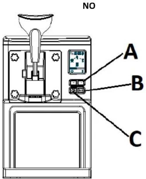
3.1. Device description
- Funnel
- Feeder lever
- Control panel
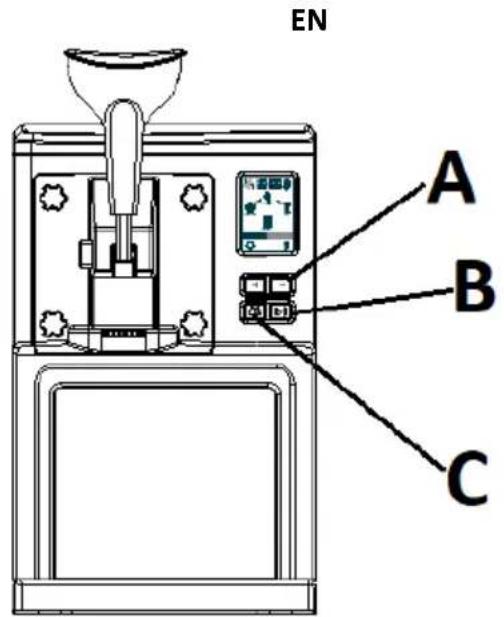
A. Time increase/decrease buttons
B. Menu button
C. Start/Pause button
- Fastening nuts
- Protective panel
- Drip tray
- Lid
- Display
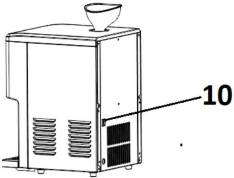
- Ventilation holes
- Power switch (0 / I)

3.2. Preparing for use
APPLIANCE LOCATION
The temperature of environment must not be higher than 40^ C and the relative humidity should be less than 85%. Ensure good ventilation in the room in which the device is being used. There should be at least 8 cm distance between each side of the device and the wall or other objects. Keep the product away from hot surfaces. The device should always be used when positioned on an even, stable, clean, fireproof and dry surface, and be out of the reach of children and persons with limited mental and sensory functions. Position the device such that you always have access to the power plug. The power cord connected to the appliance must be properly grounded and correspond to the technical details on the product label.
Before the first use, disassemble all elements and wash them, i.e. cooling drum, measuring cup, agitator spirals, feeder ring gasket, feeder lid or funnel.
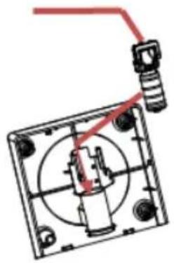
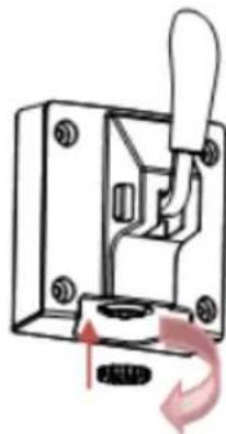
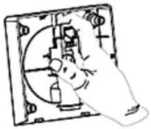
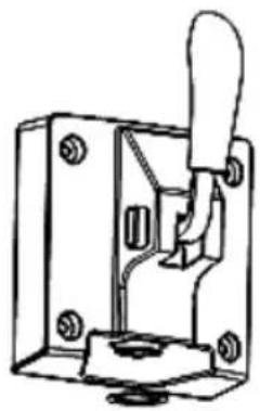
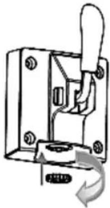
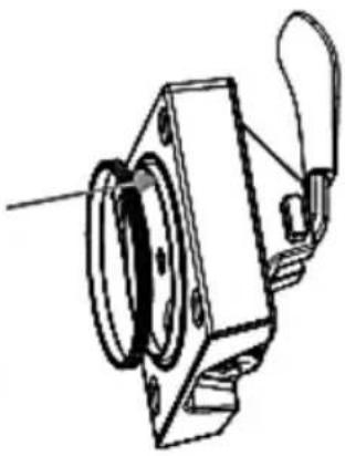
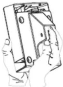
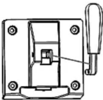
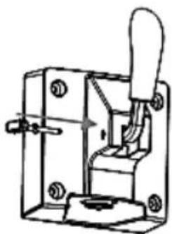
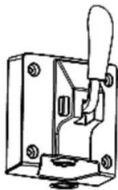
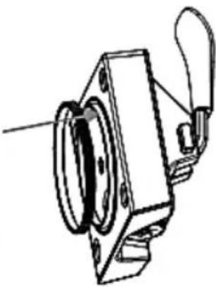
ASSEMBLING THE APPLIANCE
a) Mount the agitator spiral taking care that its outlet matches the gearing spindle.
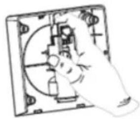
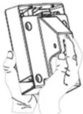
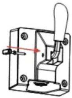
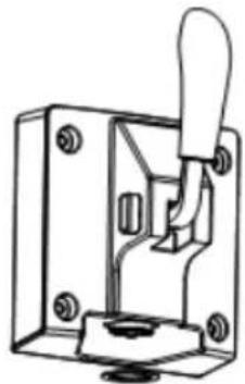
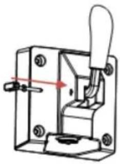
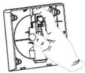
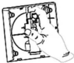
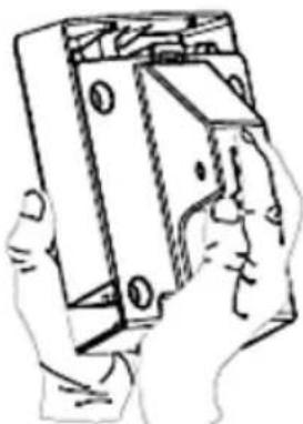
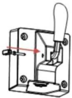
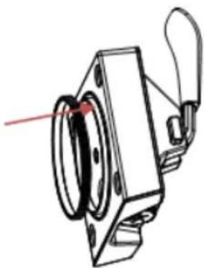
b) Fasten the feeder lever:
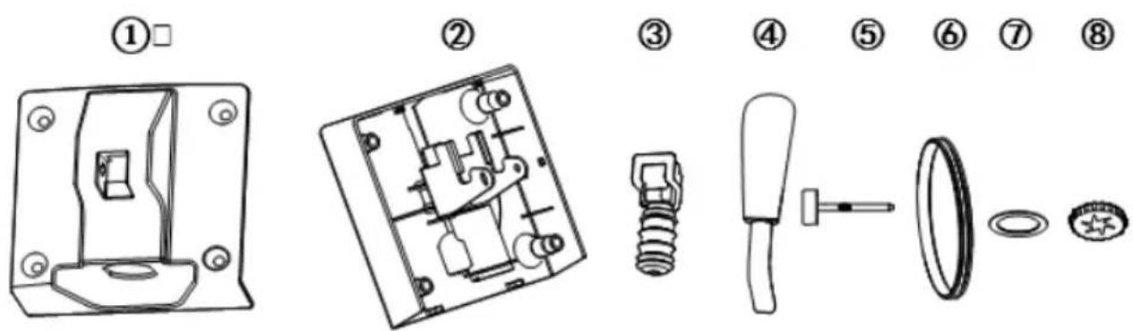
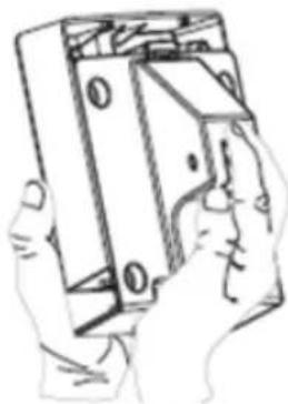
1) Insert part no. 3 into part no. 2 as on the picture below no.1 – with the socket facing up.
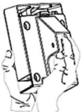
2) Manually press part 3 into part 2 as on the picture 2 below.
3) Fasten part 1 to 2 as on the picture 3 below.
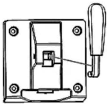
4) Insert part 4 into 3 as shown on picture # 4 below.
5) Insert part 5 into 1 as on the picture 5 below.
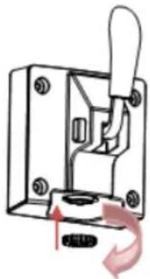
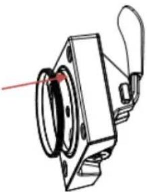
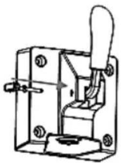
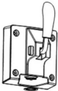
6) Attach part 7 to part 2 as on the picture 6 below.
7) Attach part 8 to 2, then tighten clockwise as on the picture 7 below.
8) Put part 8 on 2 as on the picture no. 8 below.
CAUTION: disassembly in reverse order.
natural_image
Pure mechanical assembly diagram without any text, numbers, or symbols①

natural_image
Hand operating a mechanical device with no visible text or symbols②

natural_image
Line drawing of a hand holding a rectangular object with internal components (no text or symbols)③

natural_image
Technical line drawing of a mechanical clamp or bracket with a red indicator arrow (no text or symbols)④

natural_image
Mechanical switch mechanism diagram showing lever and pivot (no text or symbols)⑤

natural_image
Technical line drawing of a toggle switch mechanism (no text or symbols)⑥
natural_image
Mechanical switch mechanism diagram showing lever and nut assembly (no text or symbols)⑦

natural_image
Technical line drawing of a mechanical component with no visible text or symbols⑧
c) Connect the device plug to a suitable power socket.
3.3. Device use
3.3.1 Preparation of the ice cream mass
A. Using a funnel inserted into the inlet hole (at the top of the device), load the machine with the appropriate amount of mixed ingredients. Then pull out the funnel and close the inlet hole with a plug.
CAUTION: make sure that the total amount of ingredients does not exceed 60% of the drum capacity (approx. 900 g) due to the fact that the ice cream mass increases in volume during production.
B. Set the power switch (on the back of the device) to the position "I" and the display will show the default production time of ice cream – "40:00". The ice icon will flash and the display backlight will turn off after a second.
C. Press the MENU button on the control panel to select the appropriate product – default production time: ice creams – 40 minutes, smoothies/shakes – 30 minutes, juices – 20 minutes. You
can increase or decrease the preparation time by pressing the +/- buttons.
IMPORTANT: the device has a built-in ice hardness sensor. This sensor can stop the agitator before the preset time has elapsed. This is not a defect of the device, it means that the ice cream is ready.
D. Press the START/PAUSE button to start the ice cream/drink process. During it, pressing the same button will pause the preparation process, and then restart. Pressing and holding this button will return the device to the standby mode, i.e. the preparation process will be interrupted.
CAUTION: while preparing the ice cream mass, you can also add spices, but make sure that they are clearly liquid or powdered, and not in the shape of granules, which may clog the feeder.
3.3.2 Serving
To serve the prepared product, pull the feeder lever downwards, and the finished food product will start to come out of the hole at the bottom of the feeder.
3.3.3 Keep warm function
The device has a built-in function of keeping the finished product in low temperature (ice cream, milk shake, juice), protecting it from defrosting. After the production process is finished, in the absence of any further action, the device will automatically activate the low temperature maintenance mode for the next 3 hours.
3.3.4 Basic recipe
A. Ice cream (300 g of water, 200 g of powdered milk, 300 g of sweet, fatty cream)
Mix the ingredients together until reaching the smooth mass without lumps. Using a funnel, add the prepared mass to the cooling drum and the preparation process ("ice cream") can begin.
B. Milk ice cream (360 g of milk, 100 g of refined cane sugar, 300 g of sweet cream)
Mix the ingredients together until reaching the smooth mass without lumps. Using a funnel, add the prepared mass to the cooling drum and the preparation process ("ice cream") can begin.
C. Powder ice cream (600 g of milk, 200 g of powdered ice cream)
Mix the ingredients together until reaching the smooth mass without lumps. Using a funnel, add the prepared mass to the cooling drum and the preparation process ("ice cream") can begin.
D. Banana shake (500 g of milk, 300 g of ripe bananas)
Blend the bananas, then add the milk and mix well together. Using a funnel, add the prepared mass to the cooling drum and you can start the shaking process.
E. Frozen juice (1 kg of clear fruit juice)
Add the juice to the drum and you can start making the iced drink ("juice").
3.3.5 Troubleshooting
| Problem | Possible cause | Solution | |
| 1 | Once the production of ice cream is finished, it cannot be served | Ice cream mass too hard | Wait about a minute and try again |
| 2 | The feed lever does not mount smoothly | The agitator spiral was not installed in the proper place | Install the agitator spiral correctly |
3.4. Cleaning and maintenance
a) Unplug the mains plug and allow the device to cool completely before each cleaning, adjustment or replacement of accessories, or if the device is not being used.
- Wait for the rotating elements to stop.
b) Use only mild, food-safe detergents to wash the device.
c) After cleaning the device, all parts should be dried completely before using it again.
d) Store the unit in a dry, cool place, free from moisture and direct exposure to sunlight.
e) Do not spray the device with a water jet or submerge it in water.
f) Do not allow water to get inside the device through vents in the housing of the device.
g) Clean the vents with a brush and compressed air.
h) Use a soft, damp cloth for cleaning.
i) Do not use sharp and/or metal objects for cleaning (e.g. a wire brush or a metal spatula) because they may damage the surface material of the appliance.
3.4.1 Cleaning function
The device must be cleaned before and after the production of ice cream etc. First, use a funnel to pour 1 liter of running water into the drum while pressing the MENU and START/PAUSE buttons to enter and start the automatic cleaning function, which lasts 10 minutes. After approx. 1 minute of the cleaning process, drain and add fresh water – repeat this operation 5 more times. When finished, disassemble the feeder lever (see ASSEMBLING THE APPLIANCE), drip tray and cooling drum and wash them. All components must be completely dry before reassembly and use.
DISPOSING OF USED DEVICES
Do not dispose of this device in municipal waste systems. Hand it over to an electric and electrical device recycling and collection point. Check the symbol on the product, instruction manual and packaging. The plastics used to construct the device can be recycled in accordance with their markings. By choosing to recycle you are making a significant contribution to the protection of our environment. Contact local authorities for information on your local recycling facility.

natural_image
Pure mechanical assembly diagram without any text, numbers, or symbols①
natural_image
Hand inserting a component into a square electrical socket (no text or symbols visible)②
natural_image
Hand holding a rectangular electronic device with a grid of pins (no text or symbols visible)③
natural_image
Technical line drawing of a mechanical switch or bracket assembly (no text or symbols)④
natural_image
Technical line drawing of a toggle switch mechanism (no text or symbols)⑤
natural_image
Technical line drawing of a toggle switch mechanism (no text or symbols)⑥
natural_image
Mechanical switch mechanism diagram showing lever and base components (no text or symbols)⑦
natural_image
Technical line drawing of a mechanical device with no visible text or symbols⑧
natural_image
Pure mechanical assembly diagram without any text, numbers, or symbols①

natural_image
Hand operating a mechanical device with no visible text or symbols②
natural_image
Line drawing of a hand holding a rectangular object with internal components (no text or symbols)③

natural_image
Technical line drawing of a mechanical clamp or bracket with a red indicator arrow (no text or symbols)④
natural_image
Mechanical switch mechanism diagram showing lever and pivot (no text or symbols)⑤

natural_image
Technical line drawing of a mechanical switch or bracket component (no text or symbols)⑥

natural_image
Mechanical switch mechanism diagram showing lever and nut assembly (no text or symbols)⑦

natural_image
Technical line drawing of a mechanical component with no visible text or symbols⑧
natural_image
Pure mechanical assembly diagram without any text, numbers, or symbols①

natural_image
Hand operating a mechanical device with no visible text or symbols②

natural_image
Line drawing of a hand holding a rectangular object with internal components (no text or symbols)③

natural_image
Technical line drawing of a mechanical clamp or bracket with a red indicator arrow (no text or symbols)④

natural_image
Mechanical switch mechanism diagram showing lever and sliding contact (no text or symbols)⑤

natural_image
Technical line drawing of a toggle switch mechanism (no text or symbols)⑥

natural_image
Mechanical switch mechanism diagram showing lever and nut assembly (no text or symbols)⑦

natural_image
Technical line drawing of a mechanical component with no visible text or symbols⑧
natural_image
Pure mechanical assembly diagram without any text, numbers, or symbols①
natural_image
Hand operating a mechanical device with no visible text or symbols②

natural_image
Line drawing of a hand holding a rectangular object with internal components (no text or symbols)③

natural_image
Technical line drawing of a mechanical clamp or bracket with a red indicator arrow (no text or symbols)④

natural_image
Mechanical switch mechanism diagram showing lever and pivot (no text or symbols)⑤

natural_image
Technical line drawing of a toggle switch mechanism (no text or symbols)⑥

natural_image
Mechanical switch mechanism diagram showing lever and nut assembly (no text or symbols)⑦

natural_image
Technical line drawing of a mechanical component with no visible text or symbols⑧
natural_image
Pure mechanical assembly diagram without any text, numbers, or symbols①

natural_image
Hand operating a mechanical device with no visible text or symbols②

natural_image
Line drawing of a hand holding a rectangular object with internal components (no text or symbols)③

natural_image
Technical line drawing of a mechanical clamp or bracket with a red indicator arrow (no text or symbols)④

natural_image
Mechanical switch mechanism diagram showing lever and pivot (no text or symbols)⑤

natural_image
Technical line drawing of a toggle switch mechanism (no text or symbols)⑥

natural_image
Mechanical switch mechanism diagram showing lever and nut assembly (no text or symbols)⑦

natural_image
Technical line drawing of a mechanical component with no visible text or symbols⑧
APPARATETS PLACERING
1) Sæt del nr. 3 ind i del nr. 2 som på billedet under nr. 1 - med stikkontakten opad.
2) Tryk manuelt del 3 ind i del 2 som på billede 2 nedenfor.
natural_image
Pure mechanical assembly diagram without any text, numbers, or symbols①
natural_image
Diagram of a hand inserting a device into a circular component (no text or symbols visible)②
natural_image
Hand holding a rectangular object with circular components, possibly a battery or switch (no text or symbols visible)③
natural_image
Technical line drawing of a mechanical clamp or bracket with a handle and internal component (no text or symbols)④
natural_image
Technical line drawing of a toggle switch mechanism (no text or symbols)⑤
natural_image
Technical line drawing of a toggle switch mechanism (no text or symbols)⑥

natural_image
Mechanical switch mechanism diagram showing lever and adjustment mechanism (no text or symbols)⑦
natural_image
Technical line drawing of a mechanical device with no visible text or symbols⑧
natural_image
Pure mechanical assembly diagram without any text, numbers, or symbols①

natural_image
Hand operating a mechanical device with no visible text or symbols②

natural_image
Line drawing of a hand holding a rectangular object with internal components (no text or symbols)③

natural_image
Technical line drawing of a mechanical clamp or bracket with a red indicator arrow (no text or symbols)④

natural_image
Mechanical switch mechanism diagram showing lever and pivot (no text or symbols)⑤

natural_image
Technical line drawing of a toggle switch mechanism (no text or symbols)⑥

natural_image
Mechanical switch mechanism diagram showing lever and nut assembly (no text or symbols)⑦

natural_image
Technical line drawing of a mechanical component with no visible text or symbols⑧
PLAATS VAN HET APPARAAT
MONTEREN VAN HET APPARAAT
natural_image
Pure mechanical assembly diagram without any text, numbers, or symbols①

natural_image
Hand operating a mechanical device with no visible text or symbols②

natural_image
Line drawing of a hand holding a rectangular object with internal components (no text or symbols)③

natural_image
Technical line drawing of a mechanical clamp or bracket with a red indicator arrow (no text or symbols)④

natural_image
Mechanical switch mechanism diagram showing lever and sliding contact (no text or symbols)⑤
natural_image
Technical line drawing of a toggle switch mechanism (no text or symbols)⑥

natural_image
Mechanical switch mechanism diagram showing lever and nut assembly (no text or symbols)⑦

natural_image
Technical line drawing of a mechanical component with no visible text or symbols⑧
- Trakt
- Matespak
- Styrepanel
A. Tidsøknings-/reduseringsknapper
B. Meny-knapp
C. Start/Pause-knapp
- Festemuttere
- Beskyttende panel
- Dryppskål
- Lokk
- Skjerm
- Ventilasjonsspalter
- Strømbryter (0 / l)
natural_image
Pure mechanical assembly diagram without any text, numbers, or symbols①

natural_image
Hand operating a mechanical device with no visible text or symbols②

natural_image
Line drawing of a hand holding a rectangular object with internal components (no text or symbols)③

natural_image
Technical line drawing of a mechanical clamp or bracket with a red indicator arrow (no text or symbols)④

natural_image
Mechanical switch mechanism diagram showing lever and pivot (no text or symbols)⑤

natural_image
Technical line drawing of a toggle switch mechanism (no text or symbols)⑥

natural_image
Mechanical switch mechanism diagram showing lever and nut assembly (no text or symbols)⑦

natural_image
Technical line drawing of a mechanical component with no visible text or symbols⑧
c) Koble enhetens støpsel til en passende stikkontakt.
OBS! Brandrisk - brandfarliga material!

APPARATENS PLACERING
natural_image
Pure mechanical assembly diagram without any text, numbers, or symbols①

natural_image
Hand operating a mechanical device with no visible text or symbols②

natural_image
Line drawing of a hand holding a rectangular object with internal components (no text or symbols)③

natural_image
Technical line drawing of a mechanical clamp or bracket with a red indicator arrow (no text or symbols)④

natural_image
Mechanical switch mechanism diagram showing lever and pivot (no text or symbols)⑤

natural_image
Technical line drawing of a mechanical switch or bracket component (no text or symbols)⑥

natural_image
Mechanical switch mechanism diagram showing lever and nut assembly (no text or symbols)⑦

natural_image
Technical line drawing of a mechanical component with no visible text or symbols⑧
natural_image
Pure mechanical assembly diagram without any text, numbers, or symbols①

natural_image
Hand operating a mechanical device with no visible text or symbols②
natural_image
Line drawing of a hand holding a rectangular object with internal components (no text or symbols)③

natural_image
Technical line drawing of a mechanical clamp or bracket with a red arrow pointing to a component (no text or symbols present)④
natural_image
Mechanical switch mechanism diagram showing lever and pivot (no text or symbols)⑤

natural_image
Technical line drawing of a toggle switch mechanism (no text or symbols)⑥

natural_image
Mechanical switch mechanism diagram showing lever and nut assembly (no text or symbols)⑦

natural_image
Technical line drawing of a mechanical component with no visible text or symbols⑧
natural_image
Pure mechanical assembly diagram without any text, numbers, or symbols①

natural_image
Hand operating a mechanical device with no visible text or symbols②

natural_image
Line drawing of a hand holding a rectangular object with internal components (no text or symbols)③

natural_image
Technical line drawing of a mechanical clamp or bracket with a red indicator arrow (no text or symbols)④

natural_image
Mechanical switch mechanism diagram showing lever and pivot (no text or symbols)⑤

natural_image
Technical line drawing of a toggle switch mechanism (no text or symbols)⑥

natural_image
Mechanical switch mechanism diagram showing lever and nut assembly (no text or symbols)⑦
natural_image
Technical line drawing of a mechanical component with no visible text or symbols⑧
For the disposal of the device please consider and act according to the national and local rules and regulations.
CONTACT
expondo Polska sp. z o.o. sp. k.


- Technical data
- General description
- EN
- Legend
- Usage safety
- Electrical safety
- Safety in the workplace
- Personal safety
- Safe device use
- Use guidelines
- Device description
- Preparing for use
- APPLIANCE LOCATION
- ASSEMBLING THE APPLIANCE
- Device use
- Preparation of the ice cream mass
- Serving
- Keep warm function
- Basic recipe
- Troubleshooting
- Cleaning and maintenance
- Cleaning function
- DISPOSING OF USED DEVICES
- PLAATS VAN HET APPARAAT
- MONTEREN VAN HET APPARAAT
- APPARATENS PLACERING
- CONTACT
Brand : Royal Catering
Model : RC-ICMD15
Category : Ice machine