O 143 S10 - Floor cleaner Ghibli & Wirbel - Free user manual and instructions
Find the device manual for free O 143 S10 Ghibli & Wirbel in PDF.

| Product type | Single-brush floor scrubber (floor cleaner) |
| Brand | Ghibli & Wirbel |
| Model | O 143 S10 |
| Dimensions (L × W × H) | 730 × 450 × 1200 mm |
| Weight (without accessories) | 43.2 kg |
| Brush motor power | 1000 W |
| Power supply | 220–240 V~ / 110 V~, 50/60 Hz |
| Working width | 430 mm |
| Brush pressure | 25.6 g/cm² |
| Oscillations per minute | 1500 or 1800 rpm (depending on version) |
| Passage height | 270 mm (with 25 mm pad) |
| Dry suction connection | Yes |
| Noise level | 59.5 dB(A) |
| Vibration level | < 2.5 m/s² |
| Transmission | Direct |
| Power cable length | 12 m |
| Intended use | Indoor, professional (hotels, schools, hospitals, factories, shops, offices); floor cleaning, carpets, polishing |
| Available options | Water tank, additional brush, electric spray accessory |
| Recommended maintenance | Clean the machine with a damp cloth; pad washable at max 60°C; drain and clean the tank after use |
| Safety | Do not use outdoors; avoid water >50°C, corrosive detergents; do not start in inverted position |
| Spare parts | Pad, drive disc, brush, orbital unit, tank (option), spray accessory |
| Repairability | Orbital unit can be disassembled; wiring diagram provided |
Frequently Asked Questions - O 143 S10 Ghibli & Wirbel
User questions about O 143 S10 Ghibli & Wirbel
0 question about this device. Answer the ones you know or ask your own.
Ask a new question about this device
Download the instructions for your Floor cleaner in PDF format for free! Find your manual O 143 S10 - Ghibli & Wirbel and take your electronic device back in hand. On this page are published all the documents necessary for the use of your device. O 143 S10 by Ghibli & Wirbel.
USER MANUAL O 143 S10 Ghibli & Wirbel

GH30-933 ed. 04/2022
IT Uso e Manutenzione
EN Use and Maintenance
FR Utilisation et Entretien
DE Gebrauch und Wartung
ES Uso y Mantenimiento
PT Uso e manutenção
NL Gebruik en Onderhoud
CS Použití a Údržba
RU Эксплуатация и обслуживание
PL Obstuga i Konserwacja
AR
الاستخدام والصيانة
NO
IT
DATI IDENTIFICATIVI
The machine identification data and “CE” marking are located on the plate on the machine body.
It is advisable to note the machine model and serial number on the table on the next page.
FR
DONNÉES D'IDENTIFICATION
natural_image
Technical line drawing of a cleaning or maintenance tool with a mounted cart and cable (no text or symbols)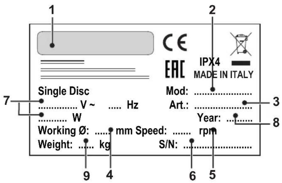
| 1 2 3 4 5 | |||||
| IT | Produttore Modello | Codice articolo ∅ di lavoro | Velocità di rotazione | ||
| EN | Manufacturer Mode | Article code Working ∅ Rotation speed | |||
| FR | Producteur Modèle | Code de l'article ∅ de travail Vitesse de rotation | |||
| DE | Hersteller Modell | Artikelnummer ∅ Arbeit Drehgeschwindigkeit | |||
| ES | Fabricante Modelo | Código del artículo ∅ de trabajo | Velocidad de rotación | ||
| PT | Fabricante | Modelo | Código do artigo | ∅ de trabalho | Velocidade de rotação |
| NL | Producent | Model | Artikelcode | ∅ bewerking | Rotatiesnelheid |
| CS | Výrobce | Model | Kód výrobku | Pracovní ∅ | Rychlost rotace |
| RU | Изготовитель | Модель | Код изделия | Рабочий ∅ | Скорость вращения |
| PL | Producent | Model | Kod artykułu | ∅ pracy | Prędkość obrotów |
| AR | الصنع | الموديل | الرمز | قطر العمل | سرعة الدوران |
| 6 | 7 | 8 | 9 | |
| IT | N° Matricola | Caratteristiche elettriche | Anno di costruzione | Peso macchina |
| EN | Serial number | Electrical characteristics | Year of construction | Machine weight |
| FR | N° de Matricule | Caractéristiques électriques | Année de construction | Poids de la machine |
| DE | Serien-Nr. Elektrische | Eigenschaften Baujahr Masch | nengewicht | |
| ES | N° de Matrícula | Características eléctricas | Año de fabricación | Peso de la máquina |
| PT | N° de Série | Características eléctricas | Ano de construcción | Peso da máquina |
| NL | Serienummer | Elektrische eigenschappen Bouwjaar Machine gewicht | ||
| CS | Výrobní č. | Elektrické v lastnosti | Rok výroby | Hmotnost stroje |
| RU | N° Паспорта | Электрические характеристики | Год выпуска | Вес машины |
| PL | Nr seryjny | Charakterystyka elektryczna | Rok produkcji | Ciężar maszyny |
| AR | الکهربائية الرقم المتسلسل | سنة الصنع المواصفات | وزن الآللة | |
Fig. 1
natural_image
Technical illustration of a mechanical device with wheels and wiring, labeled with number 1 (no text or symbols on the diagram itself)Fig. 2
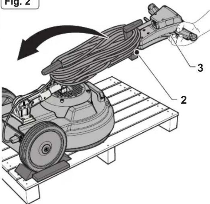
Fig. 3
natural_image
Illustration of a cleaning power tool mounted on a tiled floor, no text or symbols presentFig. 4
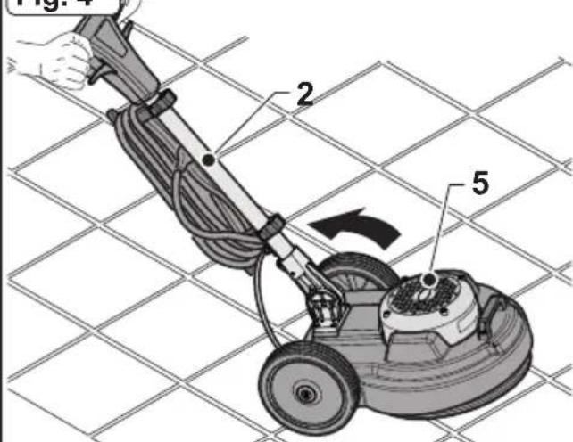
Fig. 5
natural_image
Technical illustration of a mechanical device with a hand operating it, showing no text or symbols.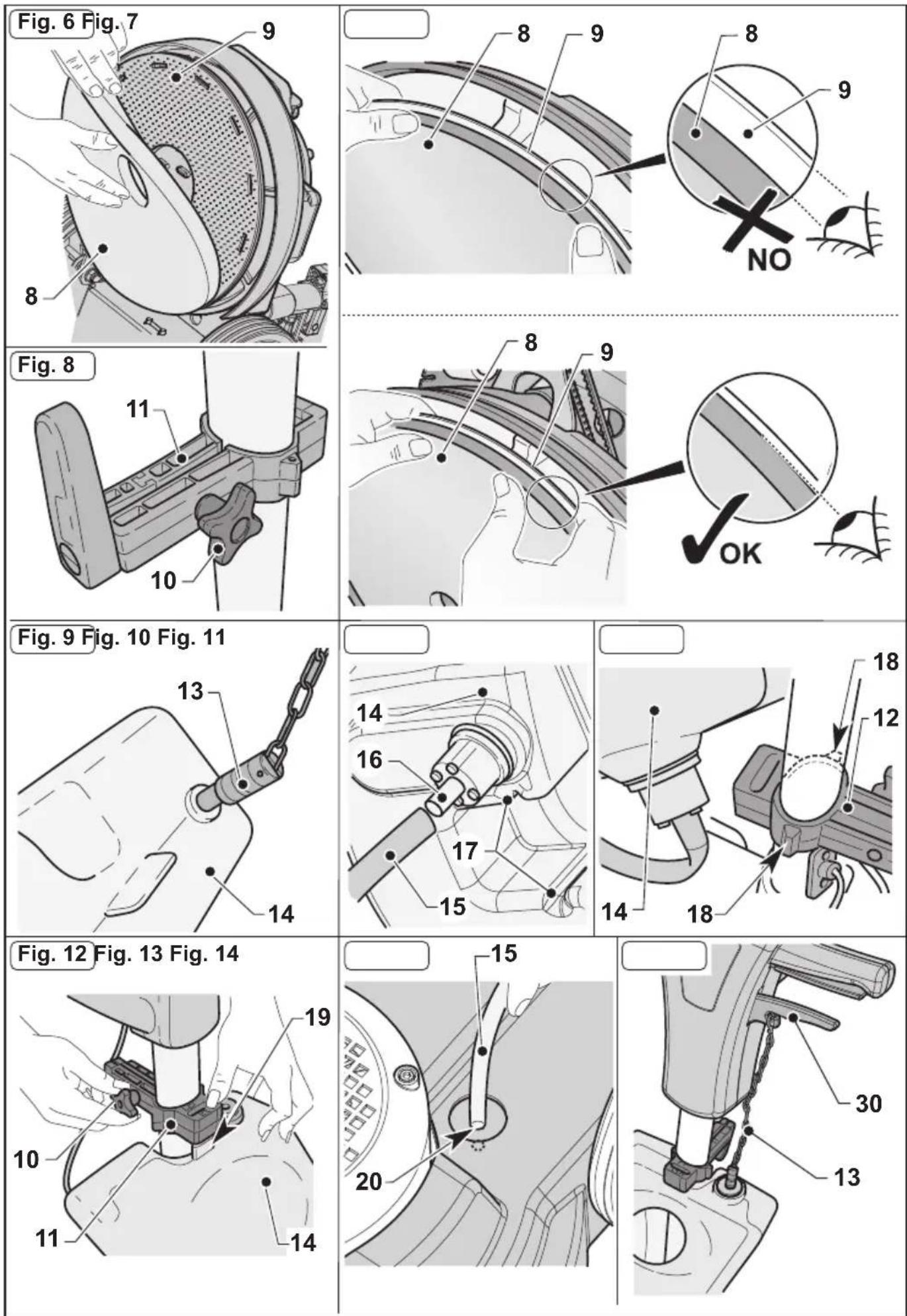
Fig. 15
natural_image
Mechanical assembly diagram showing a disc component being cut by a motor, with no visible text or symbols.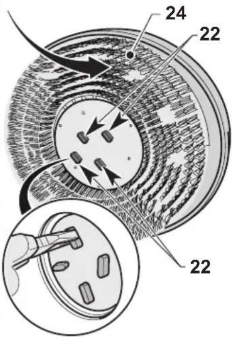
natural_image
Illustration of hands installing or adjusting a mechanical component with a numbered label (25), no readable text or symbols present.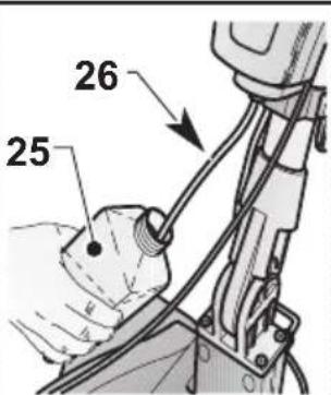
natural_image
Illustration of hands operating a mechanical device with wires and components (no text or symbols visible)Fig. 17
(EN) English ...... ENGLISH -1 (Translation of original instructions)
PROBLEMI - CAUSE - RIMEDI IT-9
SCHEMA ELETTRICO......IT-10
1.1 CARATTERISTICHE TECNICHE
Thank you for choosing one of our cleaning products.
The floor cleaner you have purchased has been designed to satisfy users in terms of ease of use and reliability.
We are aware that, in order to remain so over time, a good product requires continuous updates aimed at satisfying the expectations of those who use it daily. To this end, we hope that you will be not only a satisfied customer but also a partner who does not hesitate to let us know your views and ideas resulting from personal experience on a day-to-day basis.
Contents
1.1 TECHNICAL CHARACTERISTICS......EN-3
1.2 INTRODUCTION ......EN-3
1.3 INTENDED USE OF THE MACHINE......EN-3
1.4 NON-INTENDED USE OF THE MACHINE......EN-3
2.1 UNPACKING......EN-4
2.2 COMPONENT ASSEMBLY....EN-4
2.2.a - Pad assembly......EN-4
2.2.b - Assembling the tank (Optional)......EN-4
2.2.c - Brush assembly (Optional) ......EN-4
2.2.d - Electrical spray accessory assembly (Optional)......EN-4
2.2.e - Filling the electrical spray tank (Optional) ......EN-5
2.2.f - Electrical connection ......EN-5
3.1 KNOWLEDGE OF THE MACHINE......EN-5
4.1 HANDLE TILT ADJUSTMENT......EN-5
5.1 GUIDE HANDLE......EN-6
6.1.a - Checks to be performed before use......EN-6
6.1.b - Starting the machine ......EN-6
6.1.c - Using the machine ......EN-7
6.1.d - End of use and shutdown ......EN-7
6.1.e - Transport......EN-7
7.1 MAINTENANCE AND CLEANING ...... EN-7
7.1.a - Cleaning the machine......EN-8
7.1.b - Emptying and cleaning the water tank (Optional) ......EN-8
7.1.c - Cleaning the nozzle of the spray accessory (Optional) ......EN-8
7.1.d - Pad replacement......EN-8
7.1.e - Orbiting group disassembly ......EN-8
TROUBLESHOOTING......EN-9
WIRING DIAGRAM......EN-10
1.1 TECHNICAL CHARACTERISTICS
| S10 | ||||
| Brush motor power 1000 W | ||||
| Voltage 220 - 240 V~ 110 V~ | ||||
| Frequency 50 Hz 60 Hz 50 Hz 60 Hz | Hz | |||
| Oscillations per minute | n.1500 n.1 | 800 n.1500 n. | 1800 | |
| Working width - ø brushes mm 430 | ||||
| Brush pressure 25.6 g/cm2 | ||||
| Motor passage height mm 270 WITH PAD H=25mm | ||||
| Dry suction socket YES | ||||
| Noise emission 59.5 dB(A) | ||||
| Vibration level | < 2.5 m/s2 | |||
| Drive DIRECT | ||||
| Cable length 12 m | ||||
| Weight (without accessories) Kg 43,2 | ||||
| Size 730X450X1200 mm | ||||
1.2 INTRODUCTION

DANGER:
Before using the appliance, read the accompanying "SINGLE DISC SAFETY WARNINGS" booklet carefully.
This manual forms an integral part of the machine itself. It must therefore be kept in a safe place where it is accessible to all users (operators and maintenance personnel) throughout the life of the machine until it is scrapped.
1.3 - INTENDED USE OF THE MACHINE

WARNING:
This machine is for indoor use only.

DANGER:
Any other use releases the manufacturer from liability for harm to persons and/or property and invalidates any warranty condition.
This machine is intended for commercial use, for example in hotels, schools, hospitals, factories, shops, offices and rental businesses.
The machine has been designed and built: for professional use, for cleaning floors and carpets, for polishing floors, for sanding floors (e.g. parquet and uneven surfaces).
1.4 - NON-INTENDED USE OF THE MACHINE

WARNING:
The machine is not intended for outdoor use.

DANGER:
- do not wash floors with water above 50 °C;
- do not use diesel/petrol or corrosive detergents to wash floors;
- do not wash and suck up corrosive, flammable or explosive liquids, even if diluted.
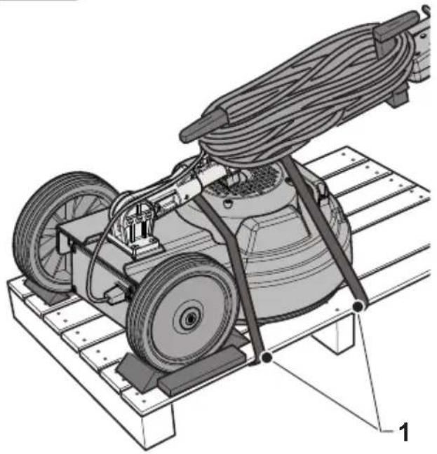
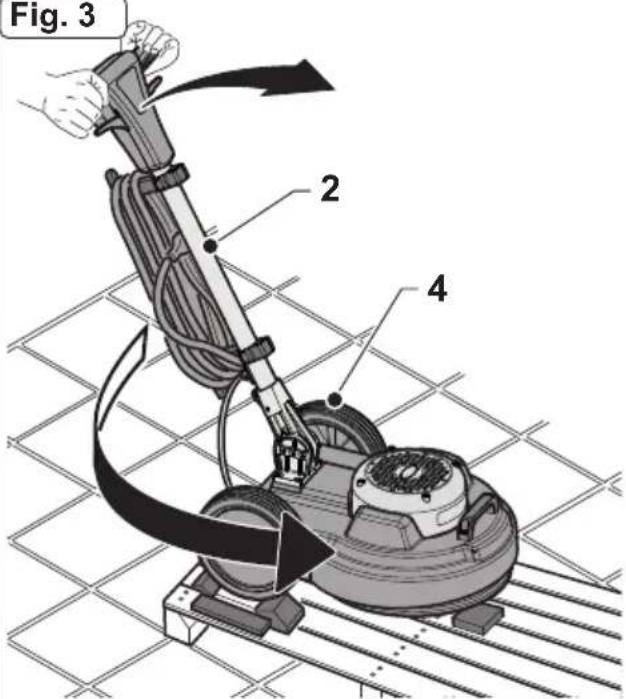
2.1 UNPACKING (Figs. 1-2-3-4)
- Upon the machine delivery, remove the external packing and then cut the holders (1) (Fig.1). Raise the handle (2) by pulling the unlocking handle (3) (Fig.2);
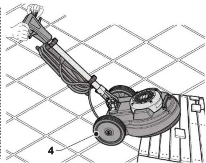
- Lift the wheels (4) by leveraging the handle (2), rotate the machine and lay the wheels on the ground (Fig. 3);
- Lift the machine body (5) by leveraging the handle (2) and move the machine (Fig. 4).
2.2 COMPONENT ASSEMBLY
2.2.a - Pad assembly (Figs. 5-6-7)
- Tilt the machine, pivoting, with the handle straight, with your feet on the wheels and place it on the handle (Fig. 6).
- Mount the pad (8) on the pad holder (9) (Fig. 6).
- Make sure the outer perimeter of the pad (8) corresponds with the outer perimeter of the pad holder (9) and then lock it on the pad holder's teeth pressing down with your fingers (Fig. 7).

WARNING:
Use only pads supplied by the manufacturer for the specific machine model. Using other types of pads can compromise the safety of the machine.
2.2.b - Assembling the tank (Optional) (Figs. 8-9-10-11-12-13-14)
- Loosen he knob (10) on the upper support (11) of the handle (Fig. 8).
- Make sure that the lower support (12) rests on the base of the handle joint (Fig. 11).
-
Screw the chain (13) onto the top of the tank (14) (Fig. 9).
-
Connect the tube (15) into the fitting (16) at the bottom of the tank (14) (Fig. 10).
- Place the tank (14) on the lower support (12), by aligning the tank slots (17) with the specific support guides (18) (Fig. 11).
- Press the tank (14) so that the slots are against the end stops on the lower support (12) guides.
- Lower the upper support (11) and attach its coupling to the coupling tab (19) on top of the tank (14) (Fig. 12).
- Tighten the knob (10) on the upper support (11) of the handle (Fig. 12).
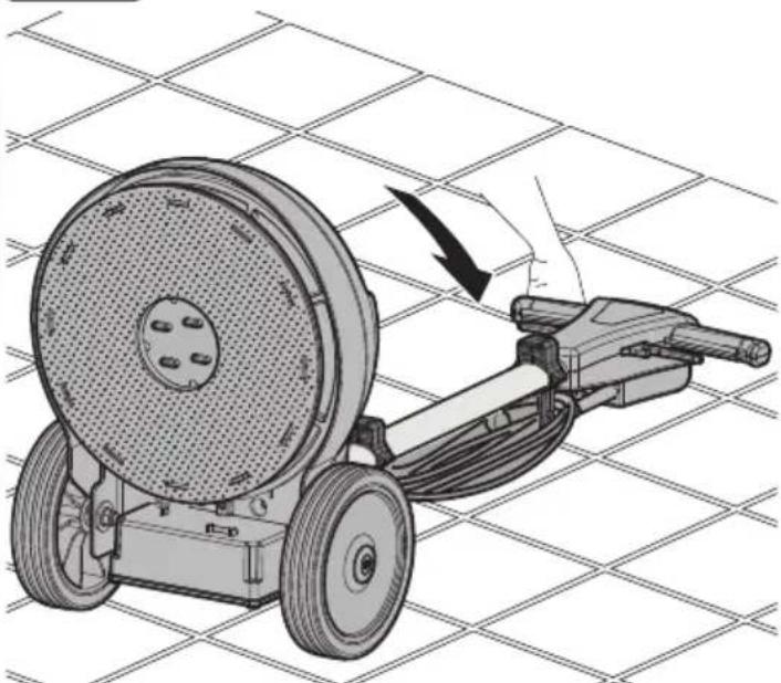
- Connect the tube (20) fitting (15) to the hole on the machine body (Fig. 13).
- Attach the chain (13) to the hook of the water supply lever (30) (Fig. 14).
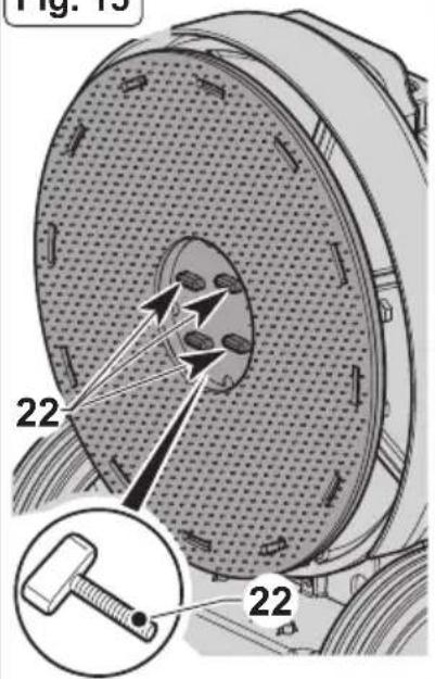
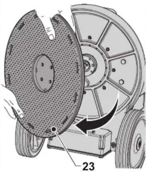
2.2.c - Brush assembly (Optional) (Fig. 15)
- Unscrew the four wing knobs (22) and remove the pad driver (23).
- Tighten the desired brush (24) in place of the driver with the wing knobs (22). Make sure to firmly tighten the wing knobs using pliers.
2.2.d - Electrical spray accessory assembly (Optional)

CAUTION:
The optional equipment may exclusively be assembled by a specialized technician following the assembly instructions that accompany the accessory.
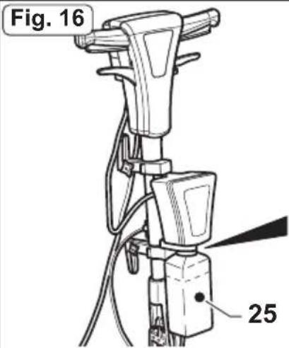
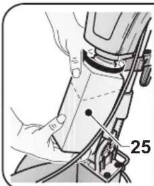
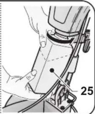
2.2.e - Filling the electrical spray tank (Optional) (Fig. 16)
- Unscrew the tank (25) and remove it.
- Fill it with water and polishing wax.
For dosing, refer to the instructions provided by the manufacturer of the polishing wax.
- Insert the suction tube (26) into the tank (25) and fully tighten.
2.2.f - Electrical connection
- Connect the machine power cable to a mains socket whose characteristics correspond to those shown on the machine's technical data plate.

WARNING:
- Unwind the power cable completely before turning on the appliance.
- Use an extension cord only if in perfect condition and make sure the diameter is appropriate for the power of the appliance.
- Never allow the power cable to slide over sharp edges and do not crush it.
- The socket should be easily accessible.
- Make sure the electrical cable is not damaged.
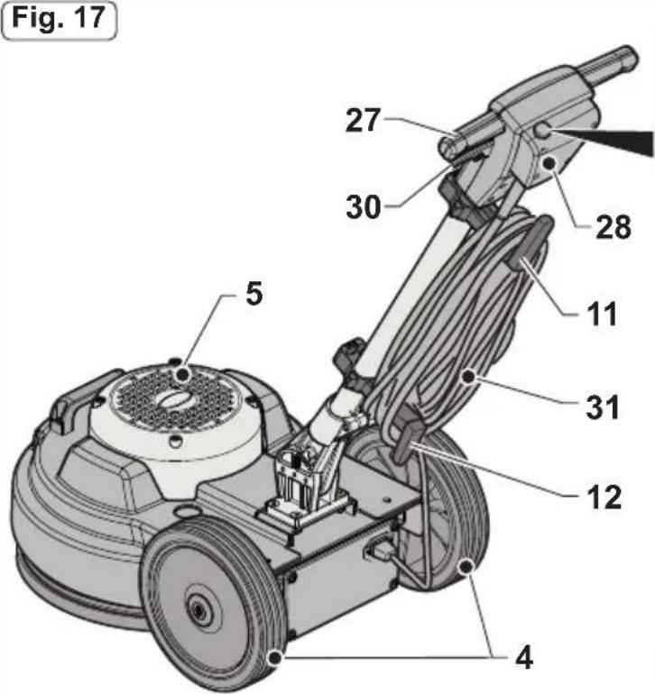
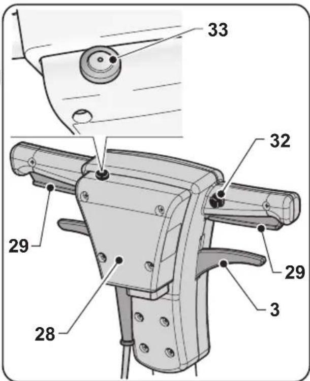
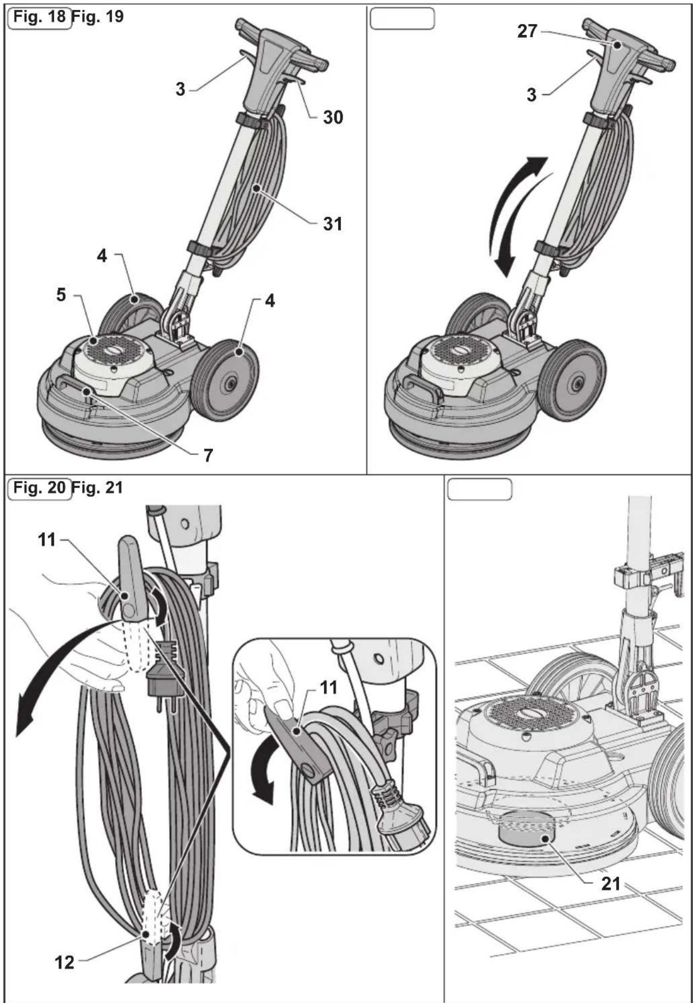
3.1 KNOWLEDGE OF THE MACHINE (Figs. 17-18)
4) Wheels
3) Handle tilt lever
5) Machine body
7) Head lifting and machine movement handle
11-12) Supports
27) Guide handle
28) Electric control box
29) Brush rotation start levers (on-off)
30) Water supply adjustment lever
31) Power cable
32) Brush rotation lever release button
33) Wax spray start button (Optional)
4.1 HANDLE TILT ADJUSTMENT (Fig. 19)

WARNING:
The handle position must be adjusted while the appliance is at a standstill.
- Pulling the lever (3) the handle position can be adjusted (27); when the lever is released, the handle is positioned and locked in the closest position required.

NOTE:
Adjust the handle to a comfortable position, depending on your height, in order to easily push the machine in straight paths. Never start the machine without having tilted the handle correctly.
5.1 GUIDE HANDLE (Fig. 17)
1) Pad rotation lever release button (32)
Press the button (32) to release the pad rotation start levers (29).
2) Pad rotation start levers (29)
Pulling the pad rotation levers (29) enables pad rotation.
When the levers (29) are released, pad rotation stops and the machine stops automatically.
The levers (29) should be kept pulled to achieve continuous machine operation.
3) Water supply adjustment lever (30) (in the presence of an optional tank)
Pulling the lever (30) activates the water supply for washing the floor.
When the lever is released (30) the water supply is interrupted.
4) Polishing liquid spray button (Optional) (33)
When the button is pressed and held down, the polishing liquid spray is activated; if the button is released, the spray stops.

NOTE:
The spray works even when the pad is not rotating.
6.1 OPERATION
6.1.a - Checks to be performed before use
- If the electrical spray accessory is mounted (Optional), check that it contains enough polishing liquid for the working phase and that the nozzle is properly connected and adjusted.
- Check the condition of the pad. If worn, replace it.
- Check that the appliance, particularly the mains cable, is not damaged in any way that might compromise correct machine operation or the operator's safety.
6.1.b - Starting the machine (Fig. 17)

WARNING:
Do not start the machine if it is tilted.
Do not start the machine if the pad is not correctly mounted.

DANGER:
Ensure your hands are dry before using the appliance.
- Pull the lever up (3) and lower the handle until it reaches the height desired.
- Press the button (32) to release the pad rotation start levers (29).
- Pulling the levers (29) starts the machine.
- When both levers (29) are released, the machine stops.

WARNING:
Never wrap the network cable around the operator the operator's neck or the machine body.
6.1.c - Using the machine (Fig. 17)
- After starting the machine, begin cleaning by keeping the levers (29) pressed, thus keeping the machine running and brush rotation active.

DANGER:
During operation, avoid passing over the power cable with the machine: this could cause serious damage and dangerous situations!

WARNING:
Using the machine in a fixed position with the pad rotation enabled for a prolonged period of time can cause damage to the floor.

NOTE:
When the levers (29) are released, pad rotation stops and the machine turns off
6.1.d – End of use and shutdown (Fig. 17-20-21).
- Release the levers (29) to stop pad rotation and turn off the machine (Fig. 17).
- Put the handle in an upright position.
- Remove the tank (Optional), empty the solution and clean the nozzle as indicated in the maintenance paragraph.
- Unplug the power cable from the socket and wrap it around the cable reel supports.
- Roll up the cable on the supports (11) (12) (Fig. 20).
- To remove the cable from the supports, turn the hooks (11) (12) inward and remove the cable without necessarily unwinding it (Fig. 20).

WARNING:
Do not leave the machine stopped with the fitted pad or driving disc resting on the floor, to prevent them from being damaged.
Place a support (21) underneath and in the centre of the disc, to raise the pad or dragging disc off the floor (Fig. 21).
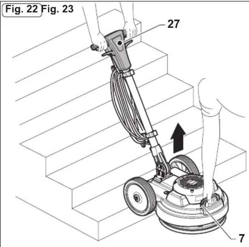
6.1.e - Transport (Fig.22)
Making sure that the mains plug is disconnected and the handle is in an upright position, lift the machine body by turning the handle downwards.
The machine can then be transported on the wheels.
If it is necessary to lift the machine for loading on trucks or for climbing stairs, proceed as follows:
- Two persons must raise the machine: one on the guide handle (27) and the other through the handle (7).
7.1 MAINTENANCE AND CLEANING

WARNING:
For information and warnings relating to maintenance or cleaning, follow what is described in the “Safety warnings for single disc” manual, accompanying this document.
OPERATIONS TO BE CARRIED OUT DAILY
7.1.a - Cleaning the machine
Clean the machine with a damp cloth and then wipe it with a clean, dry cloth to prevent the formation of scale due to the effect of chemicals.

WARNING:
Do not use solvents, acids or corrosive substances for cleaning the machine. If the pad is dirty, wash it at a maximum temperature of 60°.
7.1.b - Emptying and cleaning the water tank (Optional)

WARNING:
Once you have finished washing, you must drain and clean the water tank to prevent deposits or scale.
To empty the water tank, release it from its supports.
7.1.c - Cleaning the nozzle of the spray accessory (Optional) (Figs. 16-17).

WARNING:
Once you have finished polishing, you must drain and clean the water tank to prevent deposits or scaling and you must clean the nozzle.
- Remove the tank (25) (Fig. 16), empty the solution, rinse it and refill it with water.
- Position yourself with the machine near a discharge drain and press the button (33) (Fig. 17) until the tank is empty.
OPERATIONS TO BE CARRIED OUT WHEN NECESSARY
7.1.d - Pad replacement
The pad must be replaced when it is worn and its thickness is less than 10 mm; see the "Pad Assembly" paragraph for replacement instructions.
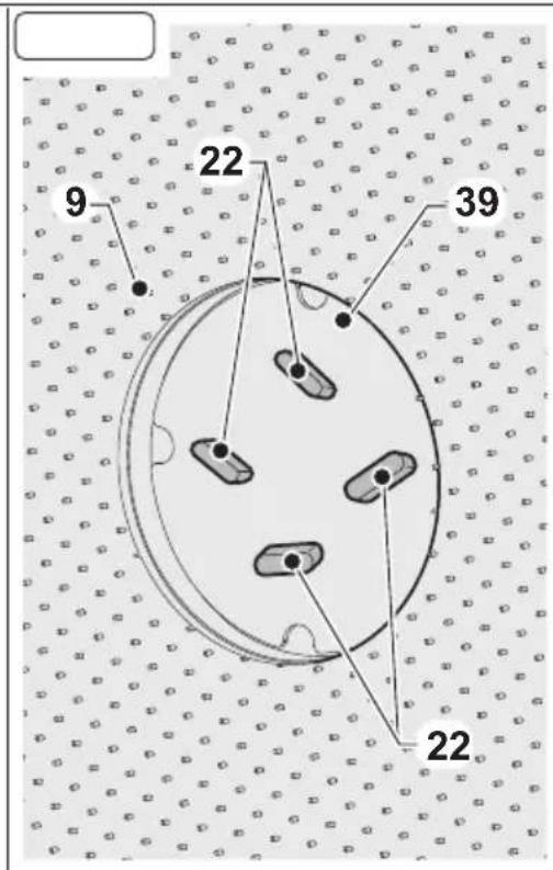
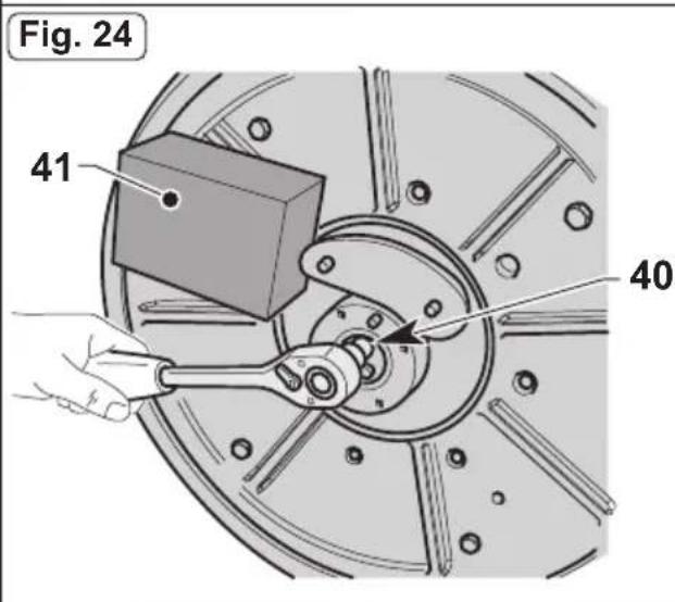
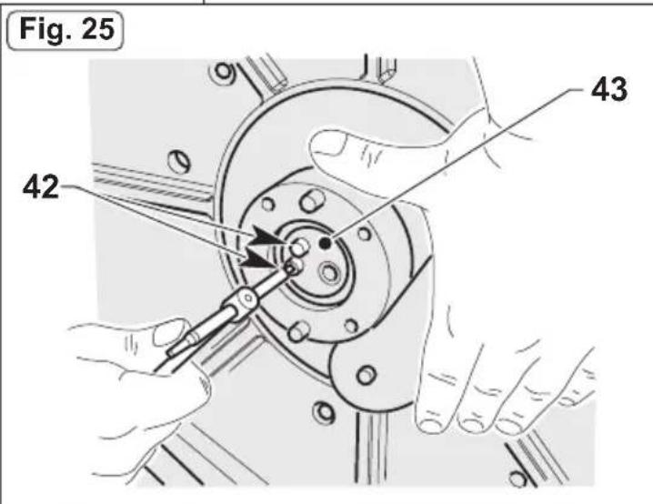
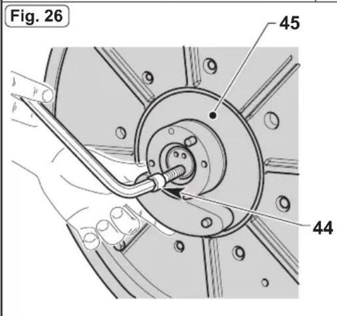
7.1.e - Orbiting group disassembly (Fig. 23-24-25-26-27)
- Unscrew the four wing knobs (22) and remove the disc (39) and the driver disc (9).
- Unscrew the hexagon head screw (40) by blocking the rotation through a contrast surface (41)
- Unscrew the two screws (42) and remove the cover (43).
- Tighten the supplied M12 Allen screw (44), to extract the orbiting group (45); block the rotation using a contrast surface if necessary.

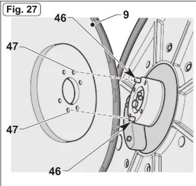
NOTE:
Reassemble everything proceeding in reverse order to the disassembly operations: when re-assembling the driver disc (9), centre the two plugs (46) of the orbiting group (45) on the holes (47) of the driver disc.
TROUBLESHOOTING
| PROBLEM | CAUSE SOLUTION | |
| Although the lever release button and brush rotation levers are pressed at the same time, the machine does not start. | The appliance is unplugged. | Plug the appliance in. |
| The pad holder does not rotate. | The brush/pad holder rota-tion lever is not pressed. | Press the lever. |
| Presence of foreign bodies. | Remove any foreign bodies stuck in the appliance. | |
| No water is released | The tank is empty. Fill the tank. | |
| Water supply lever not pressed. | Press the lever. | |
| Polishing liquid is not re-leased. | The tank is empty. Fill the tank. | |
| Button not pressed. Press the | button. | |
| Insufficient floor cleaning | Pad or chemical product not suitable. | Use a pad or chemical prod-uct that is appropriate to the type of floor to be polished. |
| Pad worn. Replace the pad. | ||
| The machine operates erratically or vibrates heavily. | Check that the pad is perfectly centred in the pad holder. | Replace the pad, centring it correctly in the pad holder. |
| Pad not suited to floor type. | Use a pad suited to the floor surface. | |
| The machine turns off unex-pectedly during operation. | Motor thermal protection activation. | Restore the reset button until it "Clicks" and make sure to work in the correct range. |
WIRING DIAGRAM
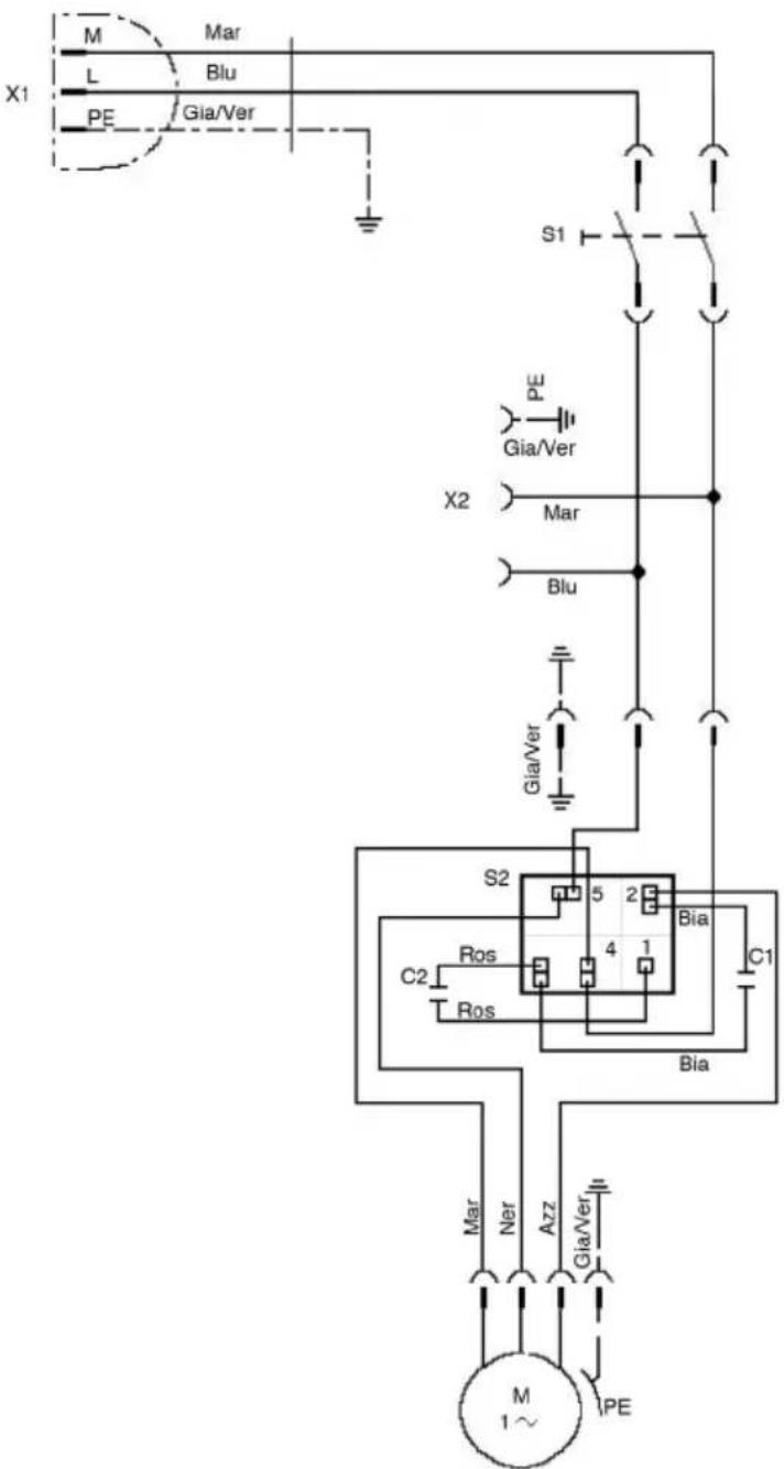
C1 Operating capacitor
C2 ....start capacitor
S2 Voltmetric relay
M1 Electric motor
S1 Main power switch
X1 Power plug
X2 ......Auxiliar socket
Ros ....Red
Bia ....White
Mar .... Brown
Blu ....Blue
Gia/Ver ....Yellow/Green
Azz Light blue
Ner ....Black
Très cher client,
PROBLÈMES - CAUSES - REMÈDES.... FR-9
SCHÉMA ÉLECTRIQUE....FR-10
1.1 CARACTÉRISTIQUES TECHNIQUES
PROBLÈMES - CAUSES - REMÈDES
S1....Interruptor principal
X1 ....Clavija
X2....Toma auxiliar
Ros....Rojo
Bia .... Blanco
Mar....Marrón
Blu......Azul marino
Gia/Ver......Amarillo/Verde
Azz Azul celeste
Ner......Negro
Prezado cliente,
PROBLEMAS - CAUSAS - SOLUÇÕES....PT-9
DIAGRAMA (ESQUEMA) ELÉTRICO....PT-10
1.1 CARACTERÍSTICAS TÉCNICAS
PROBLEMAS - CAUSAS - SOLUÇÕES
S1 Interruptor principal
X1 Cavilha
X2 Tomada auxiliar
Ros ....Vermelho
Bia ....Branco
Mar Castanho
Blu Azul Claro
Gia/Ver ...... Amarelo/Verde
Azz Azul escuro
Ner ....Preto
Beste cliënt,
1.3 - PRAWIDŁOWE UŻYCIE MASZYNY

OSTRZEŻENIE:
Professional Cleaning Machines Since 1968
DEALER
Cod. GH30-933 - 4 ^n ed. - 04/2022
GHIBLI & WIRBEL S.p.A.
Registered office:
Via Enrico Fermi, 43 - 37136 Verona (VR) - Italy
Headquarters: