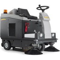
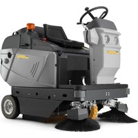
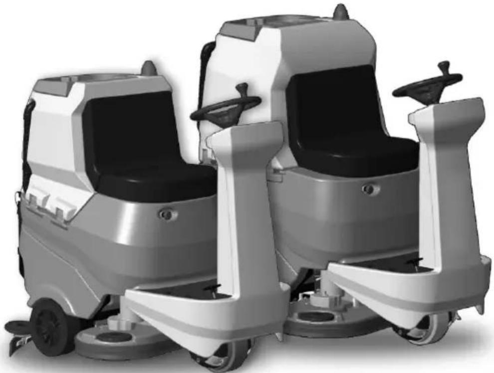
RANGER R 115 FD 85 BC CHEM - Floor cleaner Ghibli & Wirbel - Free user manual and instructions
Find the device manual for free RANGER R 115 FD 85 BC CHEM Ghibli & Wirbel in PDF.
| Product Type | Walk-behind scrubber dryer |
| Brand | Ghibli & Wirbel |
| Model | RANGER R 115 FD 85 BC CHEM |
| Washing path width | 850 mm |
| Suction width | 1050 mm |
| Dimensions (L x W x H) | 1470 x 770 x 1365 mm |
| Empty weight | 246 kg |
| Operating weight (GVW) | 691 kg |
| Power supply | 24 V batteries (different types and capacities) |
| Installed power | 2210 W |
| Working autonomy (depending on battery) | Up to 7 h (320 Ah C5 battery) |
| Theoretical productivity | 5000 m²/h |
| Actual productivity | 3000 m²/h |
| Maximum working speed | 6 km/h |
| Brushes (diameter, quantity) | 430 mm / 2 brushes |
| Brush rotation speed | 165 rpm |
| Suction motor (power) | 550 W |
| Solution tank capacity | 110 l |
| Recovery tank capacity | 115 l |
| Main functions | Washing, scrubbing, drying, suction, chemical dosing |
| Operating modes | ECO, silent, extra pressure, operator programming |
| Safety | Emergency stop, operator presence sensor, anti-skid system, electromagnetic brake |
| Routine maintenance | Draining and cleaning tanks, cleaning squeegee, checking steering chain |
| Wear parts | Brushes, rubber squeegees, splash guards, filters |
| Warranty and repairability | Recommended after-sales service for component replacement |
Frequently Asked Questions - RANGER R 115 FD 85 BC CHEM Ghibli & Wirbel
User questions about RANGER R 115 FD 85 BC CHEM Ghibli & Wirbel
0 question about this device. Answer the ones you know or ask your own.
Ask a new question about this device
Download the instructions for your Floor cleaner in PDF format for free! Find your manual RANGER R 115 FD 85 BC CHEM - Ghibli & Wirbel and take your electronic device back in hand. On this page are published all the documents necessary for the use of your device. RANGER R 115 FD 85 BC CHEM by Ghibli & Wirbel.
USER MANUAL RANGER R 115 FD 85 BC CHEM Ghibli & Wirbel
RACER R 85 FD 65 R 85 FD 75
RANGER R 115 FD 75 R 115 FD 85


C E
49.0296.00 ed. 09/2023
Uso e Manutenzione
EN Use and Maintenance
FR Utilisation et Entretien
DE Gebrauch und Wartung
ES Uso y Mantenimiento
PT Uso e manutenção
NL Gebruik en Onderhoud
CS Použitá Udržba
RU 3KcnpnyaTaunn no6cnyxBaHne
PL Obstuga i Konserwacja
AR
| 1 2 3 | |||
| IT | Produttore Caratteristiche elettriche N° Matricola | ||
| EN | Manufacturer Electrical characteristics Serial N° | ||
| FR | Producteur Caracteristicques électriques N° Matricule | ||
| DE | Hersteller Elektrische Eigenschaften Serien-Nr. | ||
| ES | Fabricante Caracteristicas électricas N° Matricola | ||
| PT | Productor Caracteristicas électricas Número de série | ||
| NL | Producent Elektrische eigenschappen Serienummer | ||
| CS | Výrobce Elektrické udaje Výrobní Č. | ||
| RU | Изrobotvitел | Злесрическехарakтеристоки | Завосков № |
| PL | Producent Specyfikacja elektryczna Numer seryjny | ||
| AR | all | all | all |
| 4 5 6 | |||
| IT | Grado di protezione | Peso in ordine di marcia | Anno di costruzione |
| EN | Degree of protection | Weight in running order | Year of manufacture |
| FR | Degré de protection | Poids en ordre de marche | Année de construction |
| DE | Schutzgrad | Gewicht bei Betrieb | Baujahr |
| ES | Grado de protección | Peso en orden de marcha | Año de fabricación |
| PT | Grau de proteção | Peso em ordem de marcha | Ano de Construição |
| NL | Beschermingsgraad | Gewicht in rijklare toestand | Bouwjaar |
| CS | Ároveñ ochrany | Hmotnost v provoznim stavu | Rok vyroby |
| RU | Ваθμός προστασίας | Βάρος στην λεῖουργία ἐτος κατασκεύης | |
| PL | Stopién zabezpieczenia | Cieźar podczas eksploatazioni | Rok produktcjji |
| AR | الإستعمال dlengue dlengue dlengue dlengue dlengue dlengue dlengue dlengue dlengue dlengue dlengue dlengue dlengue dlengue dlengue dlengue dlengue dlengue dlengue dlengue dlengue dlengue dlengue dlengue dlengue dlengue dlengue dlengue dlengue dlengue dlengue dlengue dlengue dlengue DLING | الإستعمال dlengue dlengue dlengue dlengue dlengue dlengue dlengue dlengue dlengue dlengue dlengue dlengue dlengue dlengue dlengue dlengue dlengue dlengue dlengue dlengue dlengue dlengue dlengue dlengue dlengue dlengue dlengue dlengue dlengue dlengue dlengue dlengve dlengve dlengve dlengve dlengve dlengve dlengve dlengve dlengve dlengve dlengve dlengve dlengve dlengve dlengve dlengve dlengve dlengve dlengve dlengve dlengve dlengve dlengve dlengve dlengve dlengve dlengve dlengve dlengve dlengve dlengve dlengve dlengve dlengve DLING | Às |
| 7 | 8 9 | ||
| IT | Codice articolo Modello | Massima pendenza superabile | |
| EN | Item code | Model | Maximum superable slope |
| FR | Référence de l'article | Modèle Pente maximum surmontable | |
| DE | Artikelnummer | Modell Maximal befahrbare Steigung | |
| ES | Código del articulo Modelo | Máxima pendiente que se pueda superar | |
| PT | Código do artigo | Modelo Málimo declive transponível | |
| NL | Artikelcode | Model Maximaal berijdbare hellingsgraad | |
| CS | Kód položky | Model Maximálípřekonatelný sklon | |
| RU | Kód uzdejenia | Modélb | Мakсимальный predecessorннайнайнайнайнайнайнайнайнайнайнайнайнайнайнайнайнайнайнайнайнайнайнайнайнайнайнайнайнайнайнайнайнайнайнайнайнайнайнайнайнайнайнайнайнайнайнайнайнайнайн Rai |
| PL | Kod artykułu | Model | Maksymalne superable stoku |
| AR | Rozvjithiţaj | jLl | Bacillus clausii |
IT Italiano.. IT-1
Translation of original instructions)
FR Francais FR-1
NL Netherlands.. NL-1
(42) Pulsante "Ready to go"
Language selection: ITA
Display Brightness Luminosity display
Display Brightness Luminosity display
Dear Customer,
Thank you for choosing one of our cleaning products.
The floor scrubber dryer that you have purchased has been designed to satisfy the user in terms of ease of use and reliability over time.
We are aware that in order for a good product to stay that way, over time, it requires continuous updates aimed at meeting the expectations of those who use it on a daily basis. For this reason, we hope that you will not only be a satisfied customer but also a partner who does not hesitate to give us your opinions and ideas originating from your personal day-to-day experience.
INDEX
INDEX 2
TECHNICAL DATA 3
1.1 - INTRODUCTION 5
1.1.a -Operator position 5
1.1.b - General warnings while using the machine 5
1.2 - NON-INTENDED MACHINE USE 5
2.1 - GETTING TO KNOW THE MACHINE (Fig. A) 5
3.1 - UNPACKING (Fig. B) 5
3.1.a - Battery installation (Fig. A). 6
3.1.b - Unloading the machine from the wooden pallet (Fig. B). 6
4.1 - ASSEMBLY COMPONENTS 6
4.1.a - Squeegee installation (Fig. C) 6
4.1.b -Brushes installation 6
5.1- CHARGING THE BATTERY 6
5.1.a - Charging the battery with an external battery charger (Fig. G) 7
5.1.b - Battery charging with on-board battery charger (if present) (Fig. G). 7
6.1 - MACHINE CONTROLS 7
6.1.a - Control panel (Fig. F) 7
6.1.b - Accelerator pedal (Fig. A) 10
7.1 - DISPLAY (Fig. F) 10
8.1 - EMERGENCY 11
9.1 - SAFETY DEVICES (Fig. A) 11
10.1 - FILLING THE TANK (Fig. D) 12
10.2 - DETERGENT CHEMICAL TANK (if present) (Fig. E). 12
11.1 - OPERATION (Fig. A-F) 12
11.1.a - Checks before use 12
11.1.b - Preparing the machine and choosing the cycle 12
11.1.c - Using the machine 13
11.1.d - End of use and shutdown 14
12.1 - DRAINING THE RECOVERY WATER (Fig. H) 14
13.1 - MAINTENANCE AND CLEANING 14
13.2 - OPERATIONS TO PERFORM DAILY 14
13.2.a - Emptying and cleaning the clean water tank (Fig. I). 14
13.2.b - Cleaning the recovery water tank (Fig. J) 15
13.2.c - Squeegee cleaning (Fig. K) 15
13.3 - OPERATIONS TO BE PERFORMED EVERY 3 MONTHS 15
13.3.a - Check the wear status of the steering chain (Fig. L) 15
13.4 - OPERATIONS TO PERFORM WHEN NECESSARY 15
13.4.a - Brushes replacement (Fig. M) 15
13.4.b - Splash guard rubber adjustment (Fig. M) 16
13.4.c - Replacing the squeegee rubber blades (Fig. K) 16
13.4.d - Squeegee incidence adjustment (Fig. N) 16
13.4.e - Squeegee pressure adjustment (Fig. O) 17
13.4.f - Cleaning the clean water filter (Fig. P) 17
13.4.g - Battery compartment drain tap (Fig. A). 17
13.4.h - Checking the wear status of the three wheels (Fig. A) 17
14.1 - PARAMETER SETTING (Fig. F) 18
14.1.a - OPERATOR parameters 18
15.1-FUSE CHECK/REPLACEMENT 20
16.1 - ALARMS DURING THE FUNCTIONING (Fig. F) 20
17.1 - TROUBLESHOOTING 23
18.1 - DEMOLITION OF THE MACHINE 24
19.1 - WIRING DIAGRAM 25
TECHNICAL DATA
| RACER R 85 RAN FD 65 FD 75 FD 75 FD 85 | ||||
| Driving type Ride-on | ||||
| Features | ||||
| Operation and Supply Battery 24 V | ||||
| Type of batteries | N° 2 - 12V 105Ah (C5) | N° 4 - 6V 240Ah (C5) | ||
| N° 4 - 6V 180Ah (C5) | N° 1 - 24V 320Ah (C5) | |||
| N° 1 - 24V 100Ah (Li) | N° 1 - 24V 150Ah (Li) | |||
| Installed power 2160 W 2210 W | ||||
| Running time | 2 h (105Ah C5) 5 h | (240Ah C5) | ||
| 4 h (180Ah C5) 7 h | (320Ah C5) | |||
| 2 h (100Ah Li) 3 h | (150Ah Li) | |||
| Advancement Forward / reverse drive | ||||
| Washing track width 650 mm 750 mm 750 mm 850 mm | ||||
| Suction width 850 mm 950 mm 950 mm 1050 mm | ||||
| Productivity theoretical | 4000 m²/h | 4500 m²/h | 4500 m²/h | 5000 m²/h |
| Productivity practical | 2400 m²/h | 2700 m²/h | 2700 m²/h | 3000 m²/h |
| Hand-arm vibration system (ISO 5349-1) | < 2,5 m/s² | |||
| Whole body vibration (ISO 2631-1) | < 0,5 m/s² | |||
| Sound pressure (ISO 11203) (LpA) | 63 dB(A) | |||
| Sound pressure in silent mode (LpA) | 57 dB(A) | |||
| IP code | IPX3 | |||
| Brushes | ||||
| Diameter / pad / number | 330 mm / 13" / 2 | 380 mm / 15" / 2 | 380 mm / 15" / 2 | 430 mm / 17" / 2 |
| Motor power / number | 500 W / 2 | |||
| Brush speed | 165 rpm | |||
| Specific pressure | 30 gr/cm² | 21 gr/cm² | 21 gr/cm² | 17 gr/cm² |
| Specific pressure (extra pressure) 46 gr/cm² | 2 | 32 gr/cm² | 43 gr/cm² | 34 gr/cm² |
| RACER R 85 RAN FD 65 FD 75 FD 75 FD 85 | GER R 115 FD 85 | |||
| Traction | ||||
| Maximum slope of use during work 2 % | ||||
| Maximum slope when empty (*) 12 % | ||||
| Drive motor power 600 W | ||||
| Maximum forward speed 6 km/h | ||||
| Suction | ||||
| Motor power 550 W | ||||
| Depression (water column) 125 mbar / 125 mmH 2O | ||||
| Air flow 30 l/sec | ||||
| Tank | ||||
| Typology Double tank | ||||
| Solution capacity 80 l 110 l | ||||
| Recovery capacity 85 l 115 l | ||||
| Dimensions | ||||
| Machine dimensions (length x width x height) | 1375 x 705 x 1230 mm | 1470 x 770 x 1365 mm | ||
| Machine width - Brushes deck | 715 mm | 785 mm | 785 mm | 890 mm |
| Machine width - squeezegee | 885 mm | 950 mm | 950 mm | 1055 mm |
| Battery compartment dimensions (length x width x height) | 380 x 540 x 310 mm | 380 x 625 x 440 mm | ||
| Weight | ||||
| Empty weight | 213 kg | 246 kg | ||
| Weight with Gel 12V 105Ah batteries | 285 kg | - | ||
| Weight with Gel 6V 180Ah batteries | 333 kg | - | ||
| Weight with Lithium 24V 100Ah battery | 249 kg | - | ||
| Weight with Gel 6V 240Ah batteries | - | 432 kg | ||
| Weight with Pb Wet 24V 320Ah battery | - | 506 kg | ||
| Weight with Lithium 24V 150Ah battery | - | 288 kg | ||
| Gross vehicle weight (GVW) | 490 kg | 691 kg | ||
(*) The machine was tested under the following conditions:
- Standard battery
Empty tanks - Raw concrete ramp
Ramp length 15 m - 75 kg of operator
1.1 - INTRODUCTION

NOTE:
The numbers and the figure references shown in brackets refer to the components indicated in the annexed illustrative sheet.

DANGER:
Before using the machine carefully read the "SAFETY WARNINGS FOR FLOORS WASHER-DRYER" manual annexed to this one and the additions indicated below.
1.1.a - Operator position
The operator, during the machine use is sitting on the seat with his hands on the steering wheel.
1.1.b - General warnings while using the machine
- DO NOT leave the machine unattended on inclined surfaces.
- It is absolutely forbidden to turn while on ramps; danger of tipping/overturning.
- Avoid using the machine in environments where there is a risk of falling objects.
1.2 - NON-INTENDED MACHINE USE
- Do not operate the machine with the recovery tank open.
- Hands and feet must be kept on board while the machine is in motion.
- Do not make sudden turns, especially during downhill movements.

WARNING:
Only ONE PERSON at a time is to be permitted on board the machine.
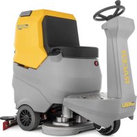
2.1 - GETTING TO KNOW THE MACHINE (Fig. A)
(1) Steering-wheel
(2) Dashboard
(3) Seat
(4)Operator presence sensor
(5) EMERGENCY push-button, to stop immediately all functions
(6) Foot rest
(7) Accelerator pedal
(8) Rear wheels
(9) Operating light (optional)
(10) Flashing light (optional)
(11) Recovery water tank
(12) Recovery water tank cover
(13) Clean water tank
(14) Plug
(15) Recovery water drain hose
(16) Squeegee water aspiration hose
(17) Clean water drain hose
(18) Clean water tank level tube
(19)Brushes deck
(20) Squeegee
(21)Document compartment
(22) Water filter
(23) Traction and directional wheel
(24) Squeegee support hook
(25) Recovery tank support peg
3.1 - UNPACKING (Fig. B)
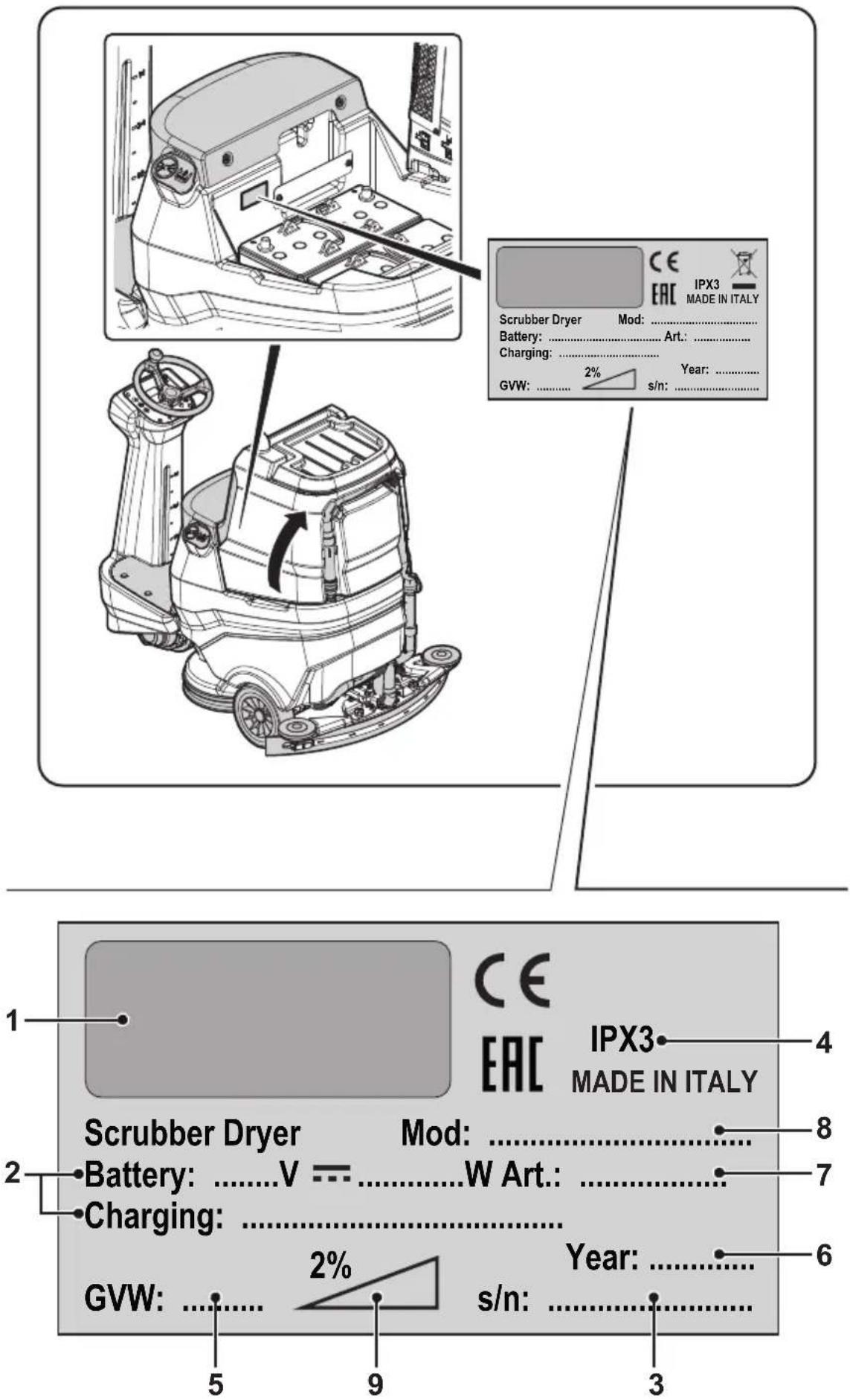
Once the packaging has been removed as indicated in the instruction sheet on the packaging itself, check the integrity of the machine and all the components supplied. If any obvious damage is found, contact your local dealer and carrier within 3 days of receipt.
- Remove the envelope and boxes (26) containing the supplied accessories:
(20) Squeegee.
(32) N° 2 brushes.
- Lift the tank unit and take the documentation from the appropriate envelope:
(33) Machine use and maintenance manual.
(34) Battery charger instruction manual (if present).
3.1.a - Battery installation (Fig. A)
- Lift the recovery tank carefully (11).
Depending on the configuration (4 6 V batteries, 2 12 V batteries, 1 package of 24 batteries), position and connect the batteries as shown in figure, using the cables and plugs provided. - Lower the recovery water tank carefully (11).

NOTE:
The batteries must be installed and connected by qualified personnel.
3.1.b - Unloading the machine from the wooden pallet (Fig. B)
- Remove the wooden block (27) positioned in front of the front wheel.
- Place the ramp (28) in front of the wooden pallet as indicated in the instruction sheet on the packaging.
- Sit on the seat (3) in driving position.
- Turn the key (29) on "ON".
- Press the travel direction button (31a)
forward travel), then press the accelerator pedal (7) and step off the pallet carefully.
4.1 - ASSEMBLY COMPONENTS
4.1.a - Squeegee installation (Fig. C)
- Insert the squeezegee (20) into its support plate (35) and fasten it by tightening the two knobs (36).
- Connect the suction tube (16) to the squeezegee's intake opening (37).
4.1.b - Brushes installation
- See procedure in the "13.4.a - Brushes replacement (Fig. M)" paragraph.
5.1 - CHARGING THE BATTERY

DANGER:
Charge the batteries in rooms which are well-ventilated and comply with applicable regulations in the country of use.
For safety-related information, follow what is described in chapter 1 of this manual.

WARNING:
For information and warnings about the battery and on board battery charger (if present) follow what is described in the battery charger manual enclosed with this document.
When the machine leaves the factory, it is calibrated to operate with gel batteries. If other types of batteries are installed, see the paragraph "Parameter setting".
The use of gel batteries with calibration for acid or other batteries is prohibited.
(Only for without on-board battery charger versions) The appliance must only be supplied at SELV (safety extra-low voltage) external battery chargers.

NOTE:
(For GEL batteries only) 10 hours are needed for complete battery charging. Avoid partial recharges.
(For lithium batteries only) It is possible to recharge partial.
Charge the batteries at the end of each job or at least when the battery symbol "on the display (41 Fig. F) starts flashing.
-
Drive the machine to the battery charging station.
-
Lift the recovery water tank (11) making sure it is empty.
5.1.a - Charging the battery with an external battery charger (Fig. G)
- Check the function of the battery charger consulting the corresponding Manual.
- The nominal voltage of the battery charger must be equal to 24V
- Take connector (39) from the appropriate housing (38) and connect it to the external battery charger.
- Connect the battery charger to the electrical network.
- When the recharging is finished, disconnect the battery charger from the network and from connector (39).
- Lower the recovery water tank carefully (11).
5.1.b - Battery charging with onboard battery charger (if present) (Fig. G)
- From the appropriate housing (38), take and connect the plug of the battery charger cable (40) to the electrical network (the network voltage and frequency must be the same as the corresponding values of the battery charger, shown in the machine's registration plate).

NOTE:
When the battery charger is connected to the electrical mains, all machine functions are automatically disabled.
- On the display (41 Fig. F), when the segments light up in sequence on the battery symbol, this means that the battery charger is charging the batteries.
- When all the segments in the battery symbol are lighted up steadily, the battery charging cycle has ended.
-
Disconnect the battery charger cable (40) from the electrical network and insert it into the appropriate housing (38).
-
Lower the recovery water tank carefully (11).
6.1 - MACHINE CONTROLS
6.1.a - Control panel (Fig. F)
(29) Ignition key
- Turned in a clockwise direction to "ON" it powers the circuits, enabling machine operation.
- Turned in an anti-clockwise direction to "OFF" it disconnects power to the circuits and can be removed.
(30) Buttons for maximum speed adjustment
It is possible to adjust the maximum travel
speed using buttons (30a) and (30b)

- Pressing the accelerator pedal (7) completely, the speed will be adjusted proportionally to the maximum set value.
- When all speed symbols " are lighted on the display (41), the accelerator pedal (7) is inhibited and the machine remains stopped.
(31) Travel direction buttons
- When the forward button (31a) “↑s pressed, the machine travels forward; the icon “↑”shows up on the display.
- When the backward button (31b) " is pressed, the machine travels backward and the backward motion buzzer is actuated; the icon " shows up on the display.

NOTE:
The maximum backward speed can be set, as in the forward travel, with buttons (30).
(41) Display
- See the specific chapter.
(42) Ready to go" button
- Pressing the button (42) on the display,
the icon " shows up and the following functions are started according to a standard setting:
- Lowering of the brushes deck and rotation of the brushes.
- Lowering of the squeezegee and starting of the suction device.
Work speed = 3^ notch (3,6km / h)
Water flow = 3^ notch.
Chemical agent = 3^ notch (1%) - Suction = normal (100%).
-
Brushes pressure = normal.
-
With this standard function activated it is possible to press any work button for any modification or adjustment.
If necessary, when a modification is set in the work functions, it is possible to save it acting as indicated below:
-
Press and keep pressed the button (42) for 3 seconds; the saving confirmation is indicated on the display (41) by the flashing of "UPDATED".
-
To deactivate the new setting and return to the standard setting values, press again and keep pressed the button (42) for 3 seconds; the confirmation is indicated on the display (41) by the flashing of "RESET".
(43) ECO button
- When pressing the button (43) on the display in the work phase, the icon "ECO shows up, the parameters of water, chemical agent, suction and holder pressure assume the following values:
Water flow = 3^ notch.
Chemical agent = 3^ notch (1%)
- Suction = silent (50%).
Brushes pressure on the floor = normal.
(44) Suction button
- Pressing the button (44) the suction device turns on and the icon " shows up on the display and, if the forward gear is engaged or if the machine is in neutral, the squeegee lowers.
- Press the button (44) again and the suction will stop and the squeezegee lifts.
- If the machine is still, the squeegee is lowered and the key (29) is on "ON" after a certain period of inactivity the squeegee will automatically lift.
(45) silent operation button
- Pressing the button (45) reduces the speed of the suction turbine, significantly reducing the noise emitted by the machine; with the function enabled, the icon appears on the display.
- Pressing the button (45) again disables the function and the machine resumes operating in standard mode, the "icon turns off and the icon appears on the display.
i NOTE:
When turning off the aspiration turbine with "silent operation" mode enabled, the operation of the turbine will automatically switch to "standard operation" mode for the entire shut-off delay time.
(46) Pushes button
- Pressing the button (46), the brushes deck lowers and the icon "..." shows up on the display.
- The brushes start rotating when the accelerator pedal is pressed, they stop when the accelerator pedal is raised.

NOTE:
The brushes rotate both in forward and reverse mode and with speed adjustment (30) at "0".
- When the machine is still, with the head lowered, the brushes still and the key (29) on "ON" position, after a certain period of inactivity the head will automatically lift.
- If you press the button (46) while the brushes are rotating, they'll stop, the unit lifts and the symbol "on the display turns off.
(47) Brushes extra pressure button
With the brush deck lowered it is possible to adjust the pressure of the brush on the floor.
- Pressing the button (47) activates the extra pressure; with the function enabled, the icon "shows up on the display.
- By pressing the button (47) again the pressure on the floor returns to normal and the icon " 串 shows up on the display.

NOTE:
Each time the brushes deck lifts (rest position), the brushes pressure sets at the minimum value.

NOTE:
The extra pressure function is equipped with a safety system that automatically recognises an excessive current absorption of the brushes motors and it's able to automatically change the lowered brushes pressure taking it to the most useful position.
(48) Chemical agent dosing button (if present)
- Pressing the button (48) the icon " shows up on the display, and the dosing of the chemical agent is prepared. The dosing pump operation is commanded by the accelerator pedal pressed.
- Pressing the button (48) repeatedly, the quantity of chemical agent increases; up to the maximum quantity viewed on the display of icon "By pressing the button (48) the function is deactivated and the icon turns off on the display.

NOTE:
In case of emptying of the chemical agent dosing system, after replacing the tank, hold and hold the button (48) pressed for at least 5 seconds to activate the air purge procedure lasting about 40 seconds; this function is activated only with the machine stopped, the key (29) in the "ON" position and with the speed adjustment (30) at "0".

Wa
- Pressing the button (49), the icon "3" shows up on the display and the opening of the water solenoid valve is prepared. The operation of the same is commanded by the accelerator pedal pressed.
- Repeatedly press the button (49) to increase the water quantity; when the maximum quantity is reached, it'll be shown on the display by the icon "If the button (49) is pressed again the function will be disabled.

Acoustic warning button
tating flashing light but-
(52) operating light button
6.1.b - Accelerator pedal (Fig. A)
- Pressing the accelerator pedal (7), the machine moves either forward or backward, according to the travel direction button that was pressed.
- The speed can be adjusted by a higher or lower pressure on the accelerator pedal.
- Release the accelerator pedal (7) to slow down the machine until it stops. After a few seconds after the machine is still the parking brake automatically activates; this brake will be disabled when the accelerator pedal (7) is pressed with forward or reverse motion on.
7.1 - DISPLAY (Fig. F)
With the machine running, the following icons show up on the display (41):

Battery
Indicates the charge status of the batteries:

Battery charged

Battery discharged

Maximum advance speed
With buttons (30a) "and (30b) " the maximum speed attainable by the machine is set with the accelerator pedal (7) completely pressed:
The travel direction arrow indicates the selected advance function by acting on buttons
(31a)“and (31b)“.

"Ready to go"
It is viewed on the display when the button
(42) "is pressed.

ECO mode
Is shown when the ECO function is active
through the button (43)

Suction device working
Is viewed on the display when the button (44)
" is pressed, indicating that the suction device is on and the squeegee is low.

Silent operation
With the suction device on. Is viewed on the display when the button (45)
pressed, indicating that the suction device is working with a reduced rotation regime.

Preparation of brushes rotation
Is viewed on the display when the button (46)
pressed, indicating that the brush rotation is enabled.

Extra-pressure
Is viewed on the display indicating the brush operation pressure.
Press the button (47) "to change the work pressure.

Detergent dispenser (if present)
Is viewed on the display when the button (48)

ressed.
Press the button to increase or reduce the percentage of detergent being dosed:
| 0,2% | 0,5% 1% | 2% 3% |

Preparation of the water flow
Is viewed on the display when the button (49)

pressed, indicating that the water olenoid valve is enabled.
When the water level in the tank is at a minimum, the icon " 2 " is viewed in full screen combined with the acoustic signal.
Replenish the water tank (13) as indicated in the specific paragraph, then turn off and restart the machine

Absence of the operator on the driver's seat
This icon warns when the operator is not correctly seated on the driver's seat and blocks all the machine functions.

Maximum liquid level in recovery tank
This displays when the fluid in the recovery tank has reached the maximum level.

Accelerator pedal pressed
This icon inserts when the machine starts indicating a wrong starting operation sequence, to remove the alarm release the accelerator pedal (7 Fig. A).
8.1 - EMERGENCY
The emergency button (5 Fig. A) is located in an easily accessible position for the operator. It must be firmly pressed in case of an immediate need to stop the machine in all its functions.
To reactivate the machine functionality, pull the emergency button until it disengages and resets.

WARNING:
Only press the emergency button (5) with the machine running in case of a real need, do not use this procedure to stop the machine, this may cause also serious faults in the same.
9.1 - SAFETY DEVICES (Fig. A)
The machine is equipped with the following safety functions:
Operator presence sensor (4)
It blocks all the machine functions when the operator is not present in the driving seat.
Anti-skid safety system
This system reduces the speed when turning and when the machine tilts laterally to avoid sudden skids, this increasing the machine stability in any condition.
Electromagnetic brake
It is built-in the rear driving wheels (23) and keeps the machine braked when the machine is off or stopped.
10.1 - FILLING THE TANK (Fig. D)

WARNING:
Only add clean mains water to the tank at a temperature no greater than 50^ .
- Using the extractable pipe (52) fill water into the tank (13) until it is replenished.
- Do not fill the tank completely, use the level tube (18) as a reference.
- Or, if available, open cap (14) and use the waterstop intake (53, if present).

WARNING:
Always visually check the fill level to avoid the risk of floor wetting.
- At the end of the tank replenishment close the cap (14).

NOTE:
For machines without the chemical kit, fill the tank (13) with clean water and mix it with the chemical detergent.
Always follow the dilution instructions indicated in the label of the chemical product packaging, to prepare the detergent solution.
10.2 - DETERGENT CHEMICAL TANK (if present) (Fig. E)

NOTE:
Use non-foamy detergents only. For the quantities, follow the instructions provided by the detergent manufacturer according to the type of dirt.
- Raise the recovery tank (11).
- Check that in the tank (54) there's the product necessary for the working day.
In case of tank replacement work as indicate below:
- Remove the cap (55), extract the tank (54) and insert a new 5 litres one then insert the cap (55) using the small suction pipe.

DANGER:
In case of contact of the detergent with the eyes and skin, or in case of ingestion, please refer to the safety and application bulletin of the detergent manufacturer.

NOTE:
The tanks (54) to use are the standard 5 litres type which can be found on the market.
- Lower the recovery water tank carefully (11).
- Carry out the air purge (see the procedure on item "Chemical agent dosing button").
11.1 - OPERATION (Fig. A-F)
11.1.a - Checks before use
- Check that the recovery tank's drainage tube (15) is properly connected and sealed.
- Check that the squeezegee's water suctioning tube (16) is properly inserted into the recovery tank.
- Check that the coupling (37) on the squeezegee (20) is not obstructed and that the tube (16) is properly connected.
- Check the charge status of the batteries by turning the key (29) to its "ON" position and checking the charge indication on the display (41).
11.1.b - Preparing the machine and choosing the cycle
- Sit on the driving position.
- The machine can perform 4 working cycles:
Washing, brushing, drying cycle:
- Press the button "Ready to go" (42) "READY TO to prepare the detergent flow, the brushes rotation and the start of the suction device.
Drying only cycle:
- To perform only the drying cycle press the button (44) "the aspirator activates.
Brushing only cycle:
- To perform only the brushing cycle press
the button (46) "the brushes rotation is prepared.
-Brushes rotation starts when the machine, with the accelerator (7) pressed, starts moving forward or backward, or with the accelerator pressed and setting the forward speed to "0".
Washing, brushing cycle:
- Press the button (46) "to prepare brushes rotation and press the button (49)

prepare water supply.
- The brush rotation and the water flow start when the accelerator pedal is pressed with the forward or backward gear, or with the setting of the advance speed at least on the 1st notch.
11.1.c - Using the machine

DANGER:
Be extremely careful when using the machine on ramps in order to avoid roll over or situations which may cause the machine to lose its balance.

DANGER:
Avoid sudden sharp turns. Turn the wheel from lock to lock only at low speed, always considering ground conditions.
-
Turn the key (29) to "ON"; in the first 2 second after turning on, the display (41) indicates the type of batteries installed and the machine work time.
-
Select the type of work cycle to be followed.
-
Insert the desired work speed acting on buttons (30).
-
Activate the flashing light (10, optional) and the work light (9, optional).
-
Use the accelerator (7) to begin the cleaning operations.

NOTE:
Release the accelerator to stop the rotation of the brushes and the dispensing of water.

NOTE:
Proper floor cleaning and drying is performed by driving the machine forwards. When driving in reverse, the squeezegee is raised and the suction unit, for removing the water from the floor, is deactivated.
-
Adjust the washing solution quantity with the button (49) if its necessary.
-
Check the charge status of the batteries on the display (41).
11.1.d - End of use and shutdown
-
Once all of the cleaning operations have been completed, shut off, in sequence, the rotation of the brushes and the suction unit, using the relative controls according to the type of cycle being employed.
-
Turn the key (29) to its "OFF" position.
- The parking brake automatically activates.
- Empty and wash out the recovery tank and the solution tank as indicated in the relative sections.

NOTE:
When the operator gets out of the machine the parking brake automatically activates.

DANGER:
It is forbidden to park the machine on ramps.
12.1 - DRAINING THE RECOVERY WATER (Fig. H)

DANGER:
Before lifting the recovery water tank (11) make sure it is empty.
At the end of the washing cycle or when the recovery water tank (11) is full, it is necessary to empty the tank by proceeding as follows:

NOTE:
To dispose of the recovery water, comply with the standards in force in the country in which the machine is used..
- Position the machine near to a drain outlet.
- Detach the pipe (15) from its proper hook, descending it to the floor over the discharge drain.
- Unscrew the cap (56) and discharge completely the recovery water contained in the tank.

NOTE:
The amount of water that comes out can be modulated by pressing on the end of the tube (15).
- Tighten the cap (56) and replace the pipe (15) on its corresponding support.
13.1 - MAINTENANCE AND CLEANING

WARNING:
For information and warnings related to maintenance and cleaning operations please follow what is indicated in the "SAFETY WARNINGS FOR FLOORS WASHER-DRYER" annexed to this one.
13.2 - OPERATIONS TO PERFORM DAILY
13.2.a - Emptying and cleaning the clean water tank (Fig. I)

WARNING:
At the end of the washing operations, it is compulsory to drain and clean the clean water tank (13) to prevent deposits or scaling.
After draining the recovery water tank, drain the clean water tank (13) as follows:
- Position the machine over a drain outlet.
- Remove the hose (17) from the holding hooks and lay it down on the drain outlet; remove the cap (57) and drain all the water contained in the tank.
-
Wash the inside of the tank, leaving the drain hose open and adding clean water through the top opening.
-
Once finished cleaning, lift the tube (17), close it with its appropriate cap (57) and position it within its appropriate lodgings.
13.2.b - Cleaning the recovery water tank (Fig. J)

WARNING:
At the end of the washing operations, it is compulsory to clean the recovery water tank to prevent deposits or scaling and the proliferation of bacteria, odours or mould.
- Lift the cover (12).
- Remove the dirt collection basket (58) and open its cover, then clean with running water, also removing eventual pieces of paper, wood, etc... that are clogging it.
- Remove and clean the suction filter (59) with running water.
- Leaving the discharge pipe (15 Fig. H) low and the cover removed, fill with water through the upper opening (60), then flush inside the tank until clean water flows out of the discharge pipe.
- Reassemble all parts working in the reverse order.
13.2.c - Squeegee cleaning (Fig. K)
In order to clean the squeegee correctly (20), it is necessary to remove it as follows:
- Disconnect the hose (16 Fig. C) from the squeegee (20).
- Loosen the knobs (36 Fig. C) and remove the squeegee (20).
- Wash the squeezegee and in particular the rubber blades (60) and the inside of the aspiration connector (56).

NOTE:
Slf, during washing, it is clear that the rubber blades (60) and (61) are damaged or worn, it is necessary to replace them or turn them over.
- Replace all the components in reverse order.
13.3 - OPERATIONS TO BE PERFORMED EVERY 3 MONTHS
13.3.a - Check the wear status of the steering chain (Fig. L)
- Check the wear and corrosion status of the chain (63) found beneath the machine near the front wheel.
- If the chain appears corroded, it must be replaced.
- Contact the technical assistance service.
13.4 - OPERATIONS TO PERFORM WHEN NECESSARY
13.4.a -Brushes replacement (Fig. M)
The brushes must be replaced whenever they appear worn or whenever their bristles are shorter than 2cm . They must also be replaced based on the type of flooring to be cleaned; in order to replace them, perform the following operations:
- Insert a hand beneath the brush support unit (19). In order to detach the brush, turn it quickly and forcefully in the opposite direction from that in which it rotates during normal function.
- Place the new brushes beneath the brush support unit (19).
- Get into the driver's seat and turn the key (29 Fig. F) to its "ON" position.
-
Position the advance speed on value "0".
-
Press the button (46 Fig. F) to enable the brush rotation; the brush group descends.
-
Pressing the accelerator pedal (7 Fig. A), the brushes hub starts to rotate gripping the brushes, then release the pedal.
-
Press the button (46 Fig. F) again "and turn the key (29 Fig. F) to the position "OFF".
13.4.b - Splash guard rubber adjustment (Fig. M)
Depending on the type of floor to be treated or after replacing the brushes, it may be necessary to adjust the height of the splash guard rubber (64).
To adjust it, act as follows:
-
Turn the key (29 Fig. F) to the "ON" position.
-
Press the button (46 Fig. F) "on/off" to lower the brush head (19), then turn the key (29 Fig. F) to "OFF".
- Check the correct height of the splash guard rubber as shown in the figure.
- If necessary, manually act on the splash guard rubber to restore the correct height.

NOTE:
The correct height of the splash guard rubber is when, during operation and the brush head is lowered, the rubber itself is flush with the floor.
- At the end of the adjustment, restart the machine and press the button (46 Fig.
F) " Then turn the key (29 Fig. F) to "OFF".
13.4.c - Replacing the squeezegee rubber blades (Fig. K)
When it becomes clear that drying the floor is difficult or traces of water remain on the floor, it is necessary to check the wear on the squeegee rubber blades (20):
- Remove the squeegee unit (20) as indicated in the "Cleaning the squeegee" paragraph.
- Press the locking device (65) and open the handle (66).
- Remove the two rubber mounting strips (67) and remove the outer rubber (60).
- Loosen the two turnbuckles (68) and remove the locking bar (69) and the inside rubber (61).

NOTE:
When the rubber blades (60) or (61) are worn on one side, on one occasion they may be turned over.
- Replace or turn over the rubber blades (60) or (61) without inverting them.
-Replace all the components in reverse order.

NOTE:
Two types of rubber are available:
Para rubber for all types of flooring and polyurethane rubber for workshop floors with oily residues.
13.4.d - Squeegee incidence adjustment (Fig. N)
- Start the machine and press the button
(44 Fig. F)

- Adjust the speed to maximum on the 1^ notch with the buttons (30 Fig. F), press the accelerator pedal (7 Fig. A) and step away a few metres, then turn the machine off and on again.
- Use the threaded bar (70) to adjust the squeezegee blades (60) and (61) contact with the floor. Turn it clockwise for increased contact and counter clockwise for less contact.

NOTE:
When the squeegee is making proper contact with the floor, there will be no streaking on the floor during machine function and the entire length of the squeegee will be in contact with the floor.
13.4.e - Squeezegee pressure adjustment (Fig. O)
Depending on the type of floor to be treated or after replacing the squeegee rubbers, it may be necessary to adjust the squeegee floor pressure.
To adjust it, act as follows:
- Lift the recovery water tank (11) making sure it is empty.
-
Act on the adjustment screw (71) taking into account that:
-
Turning clockwise decreases the squeezegee floor pressure.
- Turning counterclockwise increases the squeegee floor pressure.
- At the end of the adjustment, carefully lower the recovery water tank (11).
13.4.f - Cleaning the clean water filter (Fig. P)
- Make sure that the tank (13 Fig A) is empty.
- Remove the cap (22) and take out the filter cartridge (72).
- Clean the filter cartridge (72) using running water.
- Reassemble everything proceeding in reverse making sure that the gasket (73) is placed correctly.
13.4.g - Battery compartment drain tap (Fig. A)
- Periodically check that there are no stagnations of water in the battery compartment.
- If necessary, position the machine near a drain, unhook the tube and open the tap (74), then drain the liquids.

WARNING:
Where the use of lead-acid batteries is foreseen, pay close attention to any leakage of liquid from the batteries themselves, the associated risks and the regulations for the disposal of liquids hazardous substances.
13.4.h - Checking the wear status of the three wheels (Fig. A)
- Check the wear status of the three wheels (8) and (23) periodically; if they appear worn or damaged, contact a technical service centre in order to have them replaced.

DANGER:
Operating the machine with worn or damaged wheels poses a danger to the operator as the machine could have less traction when turning.
14.1 - PARAMETER SETTING (Fig. F)
14.1.a - OPERATOR parameters
It is possible for the operator to have access to the menu to set the following parameters:
Language
- Type of batteries
- Display - Contrast
- Display - Luminosity
To have access to the menu act as follows: Press and keep pressed the buttons (31a)

(31b) “”, then turn the
start key (29) to "ON" to view the following screens:

| General Sets General Sets |
| ID Check Check |
| Insert password Insert password |
- Release the buttons pressed.
- Insert the 4-digit Password "0010" press
ing the buttons (30a) "br (30b)" to change the number of the flashing digit.
- Press the button (43) " to confirm and go to the next digit, to finally confirm the password and have access to the parameters list.
- Press the button (31a) “” pr (31b) “

to scroll along the following screens:
General Main
Language selection: ITA
General Main Principal configurations
Language selection Language selection

General Main Principal configurations
Battery Type Battery type selection

General Main Principal configurations
Display Tune Display contrast

| General Main Principal configurations | |
| Display Brightness | Display brightness |
Language setting:

General Main Principal configurations
Language selection Language selection
- Select the language acting on buttons (30a) “+or (30b) “”, then press
the button (43) "to confirm the selection;
-ITA = Italian
-ENG = English
Setting the type of battery:

General Main Principal configurations
Battery Type Battery type selection
- Select the type of battery acting on buttons (30a) “+” or (30b) “”, then
press the button (43) "Eco to confirm the selection;
- GEL = Gel battery
- AGM = AGM battery
WET = ACID battery
Display setting - Contrast:

General Main Principal configurations
Display Tune Display contrast
- Select the type of display contrast setting a value from "0 to 50" acting on buttons (30a) "for (30b) ", then press the button (43) "to confirm the selection.
Display setting - Brightness:

General Main Principal configurations
Display Brightness Display brightness
- Select the type of display brightness by setting a value from "0 to 10" acting on the
buttons (30a) “+br(30b) “, then
press the button (43) to confirm the selection.

NOTE:
When the selected setting is confirmed, the machine restarts and the display (41) lights up in the work operation mode.
15.1 - FUSE CHECK/REPLACEMENT

NOTE:
All machine electrical circuits are protected by auto-resettable electronic devices. The safety fuses activates only in case of serious damage.
It is recommended to have the fuses replaced by qualified personnel only.
16.1 - ALARMS DURING THE FUNCTIONING (Fig. F)
When a machine malfunction takes place, the display (41) indicates the type of alarm according to the list shown below.
Consult the list and put in place the solution recommended to restore the correct functioning of the machine.
Should the recommended remedy fail to solve the problem, get in contact with the Technical Assistance Service.
| ALARM MEANING SOLUTION | ||
| AL_1: General | Memory error Restart | the machine. |
| AL_2: General | Key malfunction | Turn off the machine for at least 10 seconds, then restart. |
| AL_3: General | Low voltage | Turn off the machine, check the status of the battery charge, fuses, contacts, cabling and connections, then restart the machine. |
| AL_4: General | Excessive voltage | Turn off the machine, check the fuses, contacts, cabling and connections, then restart the machine. |
| AL_6: General | Absence of communication with the command dashboard or display | Turn off the machine, check the contacts, cabling and connections, then restart the machine. |
| AL_7: General | Ffm communication | Turn off the machine, check the contacts, cabling and connections with the communication module and the functioning of the later, then restart the machine. |
| AL_8: General | Communication Internal 1 and 2 | Restart the machine. |
| AL_9: General | ||
| AL_10: General | Insert tag Visualisation | of missing "Tag" key: insert key. |
| AL_11: General | Invalid tag | Visualisation of wrong "Tag" key: change key or damaged key. |
| AL_12: General | Updating in progress... | Visualisation of remote parameter updating in progress: wait for the end of the updating. |
| AL_13: General | Turn off | Visualisation of parameter updating completed: restart the machine. |
| AL_41: Function | Overheating | Turn off and wait for the machine to cool down. Check the consumption of the brush and suction device motors, the status of the ambient ventilation and restart. |
| AL_42: Function | Power damaged | Turn off the machine for at least 10 seconds, then restart. |
| AL_44: Function | Relay fault | The Relay/Remote switch does not close. Check the remote switch operation. In case of relay on board, if persists replace the board. |
| AL_45: Function | Relay fault dc | Detection of Relay/Remote switch closed at start. Check the status of the remote switch contacts. In case of relay on board, if persists replace the board. |
| AL_46: Function | Over-currentBrushes | Turn off the machine, check the load (motor), the mechanics, the cabling and the connections, then look for the presence of a short circuit on the outlet, than restart. |
| AL_47: Function | Over-currentSuction device | Turn off the machine, check the load (motor), the mechanics, the cabling and the connections, then look for the presence of a short circuit on the outlet, than restart. |
| AL_48: Function | Over-currentWater pump | Turn off the machine, check the load (motor), the mechanics, the cabling and the connections, then look for the presence of a short circuit on the outlet, than restart. |
| AL_49: Function | Current measurementBrush 1 and 2 | Check the consumption and the kind of application of the brush function, then restart the machine. |
| AL_50: Function | ||
| AL_52: Function | Current measurementSuction device 1 | Check the consumption and the suction device function, then restart the machine. |
| AL_54: Function | FunctionConnectionsBrush 1 and 2 | Check the brush motors connection. |
| AL_55: Function | ||
| AL_57: Function | ConnectionsSuction device 1 | Check the suction device motor connection. |
| AL_59: Function | Unbalance Check the consumption of the brush motors. | |
| AL_61: Function | Current measurementBrush actuator | Check the consumption of the actuator motor and the status of the mechanical moving parts. |
| ALARM MEAN | ING SOLUTION | |
| AL_62: Function | Over-currentBrush actuator | Turn off the machine, check the load (motor),the mechanics, the cabling and the connections,then look for the presence of a short circuit on the outlet. |
| AL_63: Function | Limit switchBrush actuator | Check the limit switch connections / status.Active control only for BTO version. |
| AL_65: Function | Current measurementSqueegee actuator | Check the consumption of the actuator motor and the status of the mechanical moving parts. |
| AL_66: Function | Over-currentSqueegee actuator | Turn off the machine, check the load (motor),the mechanics, the cabling and the connections,then look for the presence of a short circuit on the outlet. |
| AL_80: Traction | OverheatingTraction motor | Turn off and wait for the machine to cool down.Check the consumption and the kind of application of the traction, the status of the ambient ventilation, then restart. |
| AL_85: Traction | Over-currentTraction motor | Turn off the machine, check the load (motor),the mechanics, the cabling and the connections,then look for the presence of a short circuit on the outlet, than restart. |
| AL_86: Traction | Current measurementTraction motor | Check the consumption and the kind of application of the traction function, then restart the machine. |
| AL_87: Traction | Reading of Traction Motor | Restart the machine. |
| AL_88: Traction | Electric brake fault | Turn off the machine, check the brake cabling, then restart. |
| AL_89: Traction | FaultAccelerator Pedal | Turn off the machine, check the connections and cabling, then restart. |
| AL_90: Traction | Accelerator PedalPressed | Release the pedal and restart the machine. |
| AL_91: Traction | Encoder fault | Turn off the machine, check the connections and cabling and restart. |
17.1 - TROUBLESHOOTING
| PROBLEM CAUSE | SOLUTION | |
| The machine does not start up when the key is turned. | Low battery. Check that the | battery is charged. |
| Main fuse blown. Replace the | fuse found on the battery cable. (*) | |
| Defective key. Change the key. | (*) | |
| The brush doesn't turn. Gearmotor fault. Replace gearmotor. | (*) | |
| Faulty Electronic board. Replace the electronic board. | ||
| The suction unit does not function. | Recovery tank full. Empty the tank. | |
| Defective turbine motor. Replace the turbine motor. (*) | ||
| Faulty Electronic board. Replace the electronic board. (*) | ||
| The machine does dry properly, leaving traces of water on the floor. | Aspirator off. Start up the aspirator. | |
| Aspiration tube blocked. Check | and if necessary clean the aspiration tube that connects the squeezegee to the recovery tank. | |
| Recovery tank full. Empty the | recovery tank. | |
| Squeezegee rubber blades worn. | Replace or turn over the squeezegee rubber blades. | |
| No water comes out. | Empty tank. | Fill the tank. |
| Filter clogged. | Clean the filter. | |
| Pump solenoid valve not functioning. | Replace the solenoid valve pump. (*) | |
| Defective water pump. | Replace the water pump. (*) | |
| Faulty Electronic board. Replace the electronic board. (*) | ||
| The machine does not move in working conditions. | Operator not properly seated in the driver's seat. | Sit properly in the driver's seat. |
| Defective motorwheel. Replace the motorwheel. (*) | ||
| Faulty Electronic board. Replace the electronic board. (*) | ||
| Operator presence sensor malfunction. | Replace the operator presence sensor. (*) | |
| Insufficient floor cleaning. Unsuitable brushes or deter- gent. | Use brushes or detergents which are suitable for the type of floor or dirt to be cleaned. | |
| Brushes worn. Replace the brushes. | ||
| The empty solution tank icon "E" keeps flashing. | Empty tank. Fill the tank. | |
| Tap closed. Open the tap. | ||
| Faulty flowmeter. Replace the flowmeter. (*) | ||
| There is stagnation of water in the battery compartment. | Faulty recovery tank level sensor. | Drain the water in the battery compartment with the appropriate pipe and tap. |
| Check or replace the level sensor. (*) | ||
(*) Call customer service to request replacement.
18.1 - DEMOLITION OF THE MACHINE

DANGER:
Batteries and electrical parts are to be considered as special waste and must therefore be disposed of at appropriate collection facilities, as prescribed by the current regulations in the country of use.
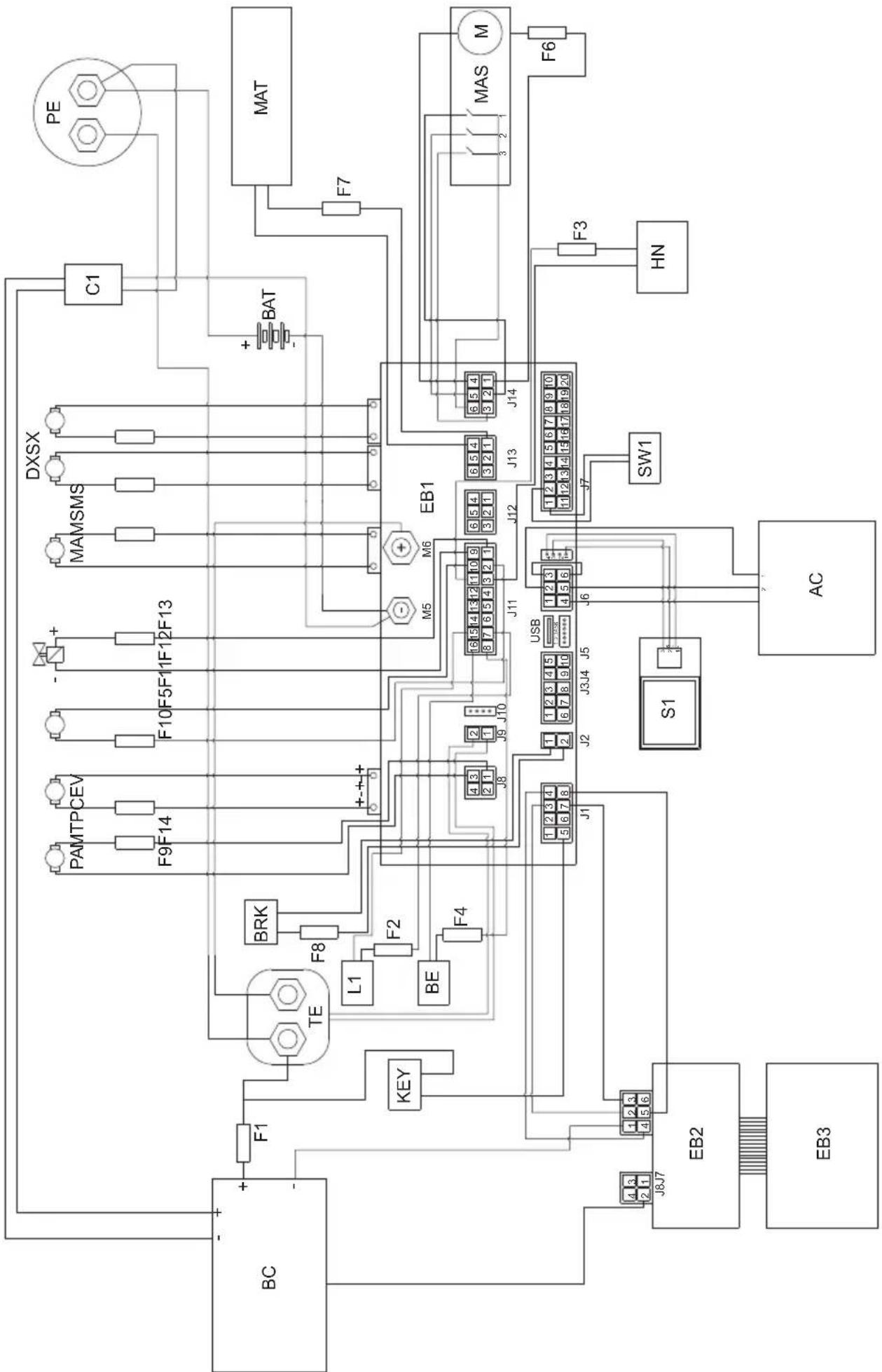
19.1 - WIRING DIAGRAM
Legend:
| AC Accelerator |
| BAT Batteries |
| BC Battery charger |
| BE Flashing light (optional) |
| BRK Electromagnetic brake |
| C1 Battery connector |
| EB1 Functions table |
| EB2 Display |
| EB3 Command panel |
| EV Solenoid valve |
| F1 Battery charger fuse (1A) |
| F2 Illumination fuse (if present) (3A) |
| F3 Horn fuse (1A) |
| F4 Flashing light fuse (if present) (1A) |
| F5 Solenoid valve fuse (5A) |
| F6 Brush deck actuator fuse (10A) |
| F7 Squeegee actuator fuse (10A) |
| F8 Electric brake fuse (7.5A) |
| F9 Water pump fuse (5A) |
| F10 Chemicals pump fuse (if present) (5A) |
| F11 Suction motor fuse (40A) |
| F12 Right brush motor fuse (40A) |
| F13 Left brush motor fuse (40A) |
| F14 Traction motor fuse (100A) |
| HN Horn |
| KEY Start key |
| L1 Work light (optional) |
| MA Suction motor |
| MAS Brush deck actuator motor |
| MAT Squeegee actuator motor |
| MS-DX Right brush motor |
| MS-SX Left brush motor |
| MT Traction motor |
| PA Water pump |
| PC Chemicals pump |
| PE Emergency button |
| S1 Recovery water level sensor |
| SW1 Seat microswitch |
| TE External remote switch |
| Colour codes: |
| BK Black |
| BU Blue |
| BN Brown |
| GN Green |
| GY Grey |
| OG Orange |
| PK Pink |
| RD Red |
| VT Violet |
| WT White |
| YE Yellow |
Cher client,
1.1 - INTRODUCTION 5
(47) Bouton extra pression brosses
F5 Fusible electrodevanne (5A)
F6 Fusible actioneur tete brosses (10A)
(42) Taste ,Ready to go"
Language selection: ITA
(42) Botón “Ready to go”
-Presione el boton "Ready to go" (42)

Language selection: ITA
17.1 - BUSQUEDA AVERIAS
F5 Fusible electrovalvula (5A)
F6 Fusible act. cabezal escobillas (10A)
F7 Fusible actuator secador (10A)
F8 Fusible electrofreno (7.5A)
F9 Fusible bomba de agua (5A)
F10 Fusible bomba chem (si está pres.) (5A)
F11 Fusible motor de aspiracion (40A)
F12 Fusible motor escobilla derecha (40A)
- Premindo o botão deavanço (31a) “a boa, a boa, a boa, a boa, a boa, a boa, a boa, a boa, a boa, a boa, a boa, a boa, a boa, a boa, a boa, a boa, a boa, a boa, a boa, a boa, a boa, a boa, a boa, a boa, a boa, a boa, a boa, a boa, a boa, a boa, a boa, a boa, a boa, a boa, aboa, a boa, a boa, a boa, a boa, a boa, a boa, a boa, a boa, a boa, a boa, a boa, a boa, a boa, a boa, a boa, a boa, a boa, a boa, a boa, a boa, a boa, a boa, a boa, a boa, a boa, a boa, a boa, a boa, a boa, a boa, a boa, a boa, a boa
Language selection: ITA
General Main Configuraçao principal
Battery Type SeLECTIOND type de bateria
F14 Fusivel motor traçao (100A)
HN Buzina
KEY Chave de ignicao
Language selection Taakeuze
pen (30a) “+of (30b) “ , druk
F1 Zekering acculader (1A)
F3 Zekering claxon (1A)
F4 Zekering knipperend lampje (1A)
F5 Zekering elektromagnetische klep (5A)
F9 Zekering waterpomp (5A)
| General Main Language selection: ITA |
| General Main | Hlavné nastavení |
| Language selection | Volba jazyka |

10.2-BIIOHMOIOEROCPEDCTBA/XIMNUECKOBOBEECTBA
( npn ero hannnn) (Pnc. E) 12
11.1 - 3KcIyATAUmaHHbl (Pnc.A-F) 12
11.1.a-KoHTpOJIb npn nCnoJIb3OBAHm 12
11.1.b - Poirotobka annapata n Bb6op zukla 13
11.1.c-Испобзовие annapata 13
11.1.d - OkonhaHne nCnoJIb3OBAHnI nOCTaHOBka 14
12.1-CINB BOI IN BOCCTAHOBJIEHNE (Pnc.H) 14
13.1-OBcJyKBAHNEIOUcTKAIbJIeCOCA 14
13.2 - EXEHNHEBHO BbINOJIHReMbIE ONEPAUIN 14
13.2.a - OnopokHeHne n ouncTka pe3epByapa dIra c6opa YnCTOn BODbl (Pnc. I) 14
13.2.b - Ouncka pe3epByapa nI BOCCTaHOBJIeHHoB BOIbI (Pnc.J) 15
13.2.c - Ouchka ckpe6ka (Pnc.K) 15
13.3 - ONEPAUIN BbINOJHREMbie KAXDbie 3 MEcra
(42) Khonka "Ready to go"
- PnHaxKATN KHOKN (42) Ha dncnnee
OTobpaKaTeCnKToPamMa "yNcAynyckaHcTc CneIyUuIe cyHKun npnCTaHApTHbIX HAcTPOkax:
OnyckaHne TeOHoro y3na n BpaueHne TcTOK.
OnyckaHne BCacbIbAHOuei 6aJIKN 3aNvCK CnCTeMbI BCacbIBaHn.
Pa6ooua ckopocTB: 3-e JeIeHne (3,6 KM/4).
PacxoI BOJb: 3-e DeJeHne.
XIMNUeCKoeBEUeCTBO:3-eJeHHe (1%)
- BcacbBaHHe: HopMaJIbHoe (100%).
- PnIXM UeTOK: HOpMaJIbHbI.
-Korda 3Ta CTAHdapTHaФyHKUaKTNBnPobHa,MOxHO HaxKaTb IIO6yIpa6OuyIO KONkyДЯJIIO6Oro N3MeHeHnI JIN Ha-CTpOKn.
Ipn Heo6xOaHmocTn, KOrDa B pa6oynx 6bIIN BHeceHbI n3MeHEny, IN MOxHO COxpaHnTb, BbIOJHNB CNeDyUuNe DeiCTBn:
-Haxmte u ydepxnBaTe KhoNky (42) B TeueHne 3 cekyH; NOtBepxKeHne CoXpaHEnr OTo6paxKaETcra Ha DnCnIee (41) MuraHem Hndncn «UPLOADED»
- YTO6bl OTMeHnTb HOByo HAcTpOmy BepHyTbcr K CTaHdapTHbIM 3HaueHnM, CHOba HaxMnte KhoNky (42) n ydepXnBaIte ee B TeueHne 3 ceKyH; NOdTBePxDeHne OTo6paXkaetcna DnCnnee (41) MraIOUeHnADnncBIO «RESET».
(43) ECO Khoonka ECO
-BoBpempa6oTbI, npn HaxaTnKHOKN (43)HaDncnlee NoBnEeTcN KKTOrpAmMa“ECO”,napaMeTpbl BODbl,XIMNUeCKOROBeeCTBa,BCacbIBAHNnPnIXMua ToCHoro y3na npINHMAOT CNeyUOune 3HaueHnra:
- PacxoI BObl: 3-e IeIeHne.
XIMNUeCKoe BeueCTBO:3-e DeJeHne (1%). -
BcacbibaHHe: 6ecwymHoe (50%).
-
PnIXm IeTOK K NOy: HopMaJIbHbI.
(44) Kmonka nbinecoca
-Пи Нжати Кногн (44) 3anyckaetc
пьлесoc, Ha Диспee NOЯВлгeТсЯ ПК-
TORpamma “”И, ecn BKNIOueH XOD
BpepeД ИИ ecn MaUNHa HaxOДNTСЯ
НЕТральбHom NOLOXeHи, onyckaetc
BCacbIBAUOua 6aJIka.
-Haxatne KhoNk (44) eue pa3 ocTaHaBJIbAeT nbIeCoc n paKeTKa NOHMaetcra.
- Pn OCTaHOBJIeHHoMaHHe,OnuIeHN HOMCKpe6KeN KIOUe (29)B NOIOXeHN "ON" NocNe nepNoDa HeaKTINBHOCTN, CKpe6OK NOHMAeTcA ABTOMaTHueCKN.
(45) Honka Tnxo pa60TbI
-Пи Нжати Ha KHONky (45) cna BcaCbIBaHn Typ6uHbI 6ydet yMeHbTaBcR,3TO N03BOJRAET 3HaHTeNbHO CHN3NTbUWM MaunHbI; ecn 3TaФyHKUNAKTINBnPoBaHa, HaДИСПпe OTO6paXaETcR CIMBOJI "
- IOBTOPOHoe HaxaTne KhoNKn (45) OTKIOuHaET cyHKUIO, mMaUNHa BO3O6HOBnAreT pa6Oy B CTAHApTHOM peXnme, 3HaQOK "rachet, a 3HaQK " NOBnEeTa Ha DnCnnee
i IPNMEUAHNE:
OcTaHOBKa BCaCbIBaHOSeI Typ6nHOc KHOJIKOJ «TnxOpa6oTbI» aKTINBnPOBaHHoJ, Typ6nHa 6yJeT aBTOMaTHueCKn nepeiDeT B CTAHdApTHbI peKIM pa6oTbI, BCE Bpemr 3aJePJKN BblKnUoyEHHa.
(46) KnoKa uetok
AkkymyIaTOPbIe 6aTape n pa3pJKeHbI

MaKcImaJIbHaNcKOpOCTb DnXeHnA BnepeD
KhoNkamn (30a) " " 山 (30b) " ycta-HaBJIINBaETcMaKcIMaJIbHaNcKOPOcTB, KO-TOpyU MaIInHa MoKeT pa3BnBaTb npi NOnHocTbU HaxaToI neaII aKceIepaTopa (7):
Pn BkJIIOeHHOM nbIIEcoce.
IopBnIeTcHa DnCnIee np HaxKATN KHOKN
(45) “Гагализиря O TOM, УТо пьile-coc pa60tae T спОнхжEHьIM YИСЛOM obopoTOB.

AknBaunBpauneHnneTkn
IopBnIeTcHa Iucnnee npn HaxkTu KhoN-
Kn (46) "CmHaHn3npya TOM, yTo aKTNBnPOBaHO BpaueHne 5eTKN.

Дононтелови npnxm
IIOABnIeTcHa DnCnIee, yKa3bIBaH a pa- 6ooye daBHeHne uetok. HaxMnte KhoNky (47) "TO6bI n3MeHHTb pa6oyee daBJIeHne.

HanoHnTe pe3epByap YnCToB BoDOn C MaKcImaJIbHOJ TempepaTpoi 50^
-Испοльз汞севимьшалг(52),нанолнITEбak(13)вдои.
- He 3aNoHnAte 6ak NOnHOCTbIO, NcNoIb-3yInTe Tpy6ky ypoBn (18) B KaueCTBe opneHTnpa.
- Ил, ecn BO3MOxHo, OTKpoIe KpbIuKy (14) n BocnoJb3yIteCb pa3beMOMacquastop (53, ecn ecTb).

OCTOPOXHO:
Bcerda Bn3yaIbHo npOBepaTe ypoBeHb 3aNoJIHeHn, YTO6bl n36eXaTb HamOKaHn NOJa.
-HaxMMTe KhoNky《Ready to go》(42)

ДЯakTnBaCnДоЗиPoBaHnMoO CpeDcTBa,ВpaScheHnI ΜeTOK NHeHnIbIneCoca.
UHKTOLbKOdyauchk:
-ДЯ BBINOJIHHeHЯФyHKUIN JINb cyuKIn
HaxMMTe KhoNky(44) “”,tanyckaetc np6ota nblncoca.
LNI TOJIbKO dIa YnCTK:
-ДЯ BBINOJIHHeHЯФУHKUIMЛИWB OYNCTKI
IeTKoHaxMnte KhoNky (46)“ 38 IyCKaETcBpaueHne IeTOK.
- ΚeTkn HauHnAOT BpaaTaBcra, KOrda Ma- uHa nC HaxKaToI neJaIbIO yCKOpEHHa (7) HauHnaet DnRaTbcRA Bnepei Ha3aI, Inn npn HaxKaToI neJaII akCeJIepaTopa I yCTaHOBKe CKOpOCTN DBNXeHHa «0».
LuknCTnpK, nctkn:
--HaxmTe KhoNky (46) 3anycka BpaueHnI uetok, HaxmTe KhoNky (49)

aKTHBnPoBAHnNcNoNb3OBA-0Dbl.
- BpaueHne 8eTOK n noaay BODbI NaHnHaOTc npn Haxatnn neaJn akcepePaTopa npn DnHexn BnpeD nn Ha3ad, nn npn yctahOBke ckopocTn nepemeueHna BnpeD He Hxke 1-ro DeJeHn.
11.1.c - Истороб Avenue annapata

ONACHO:
YdJIb MaKcMaJIbHoe BHMaHne npNcNoB3OBAHHMaUNHbI Ha
pamne, TaKIM o6pa3OM uTo6bl
npedOTbpaNTb cnTyaun, KOtOpbie
MOryTBnIaTb Ha yCTOnuHBOCTb Ma-
ShnHbl.

ONACHO:
N36eraTe pe3Knx NOBOPOTOB n DeIaTb KpyTbie NOBOPOTbl npn NOBOPote pyna Ha MaIbIX CKOpocTAX, npHmam Bo BHMamHe NOyBeHHbIe ycNoBn.
- NOBEPHNTe KIIOU (29) B NOJIOXeHne «ON»; B nepBbIe 2 cekyHdbI nocNe BkJIIOu-yeHnA DnCpIeN (41) noka3bIbAeT TnYcTaHOBJIeHHbIX aKKymyIaTOPOB I BpeMpa6Otbl MaunHbl.
- BbIbePte TnBbINOJIHReMOro pa6Oyeo UIKna.
-BBeIte Tpe6yEmyipo6oyuO cKOpocTb C NOMOUBIO KHOJOK (30).
-BkHouHTe npo6neckOBbIM MaYOK (10, onu) npaboyee ocBeueHne (9, onu). - BbINOJIHnTe OuNCTKy npn nCNoIb3OBaHnAkceIepaTopa (7).

ПОНМЕЧАНЕ:
Pn OtnyckaHn neaJn akcelepaTopa,poTauNoHHbIe 1eTKN I NOTOK BOdbl OHN OCTa-HaBnBaHTcA.

ПОНМЕЧАНЕ:
Для павильноюпдметанг/cушкno- loBBbIIOJIHЯOTc npn DBNXKeHn Bpepei; npn obpaTHOM HanpaBJIeHn, cKpe6OK noJHIMaETcN BCacbIBaHn BObl C NOla OT-KIIOUyeHa.
-Bo3MOxHo OTpeRyIuPyIe KOJIuYeCTBO MOUoIero pactbopa c NOMOuBu KHOJKN (49)
-Проверъе уровьи 3араза 6атaperи на диспee (41).
11.1.d - OkohuaHne nCnoJb3ObaHnI OCTaHOBka
- Pocne OKOHuaHnO uNCTKn BbIKIOUHTe B NocJeIOBATEJbHOCTn, POtaUNOHbIe UTeKN I NblIEOCOC BbIKIOUaTEJeMc C NcNOJIb3OBaHHeM OTHCNTeJbHbIX 3JIeMeHTOB ynpabJIeHnR B 3aBNCIMoCTn OT TnPa ZUKJa.
-ПовернITEКИОU(29)К поожене "OFF".
-TopMo3 octaHOBKn aKTbNpyetcra bTOmatnueckn. - Onopoxhnte pe3epByap dny oTpa6oTaHnOH BOdbI n pe3epByap dny pactbopa cNOMOuKak yka3aHO B OTHOCHTbHbIXceueHni.

ПОНМЕЧАНЕ:
TOrda, KOrda onepaTop BbIXOHT n3 MaunHbl, aBTOMaTnueckn aKTbBnpyetcT TOPMO3OCTaHOBKn.

ONACHO:
3anpeuaeTcnapkoBaTb MaunHy Ha naHdyc.
12.1 - CЛВ BОДы IN BOCCTAHOBJIECHNE (Pnc. H)

ONACHO:
Y6eHntecb, YTO pe3epByap dIЯ OTpa6oTahHOBdI (11) npct npexde yem noHNMaTb.
B KOHcE ZIKNa CTHnPK, INN KOrDa pe3epByap (11)IIN OTPa6oTaHHoB BObI 3aONHeH, He- o6xOIMMo ONOpOJHnTB pe3epByapa, cJeDyUOuM o6pa3OM:

ПОНМЕЧАНЕ:
Для синваOTpa6OtaHHoN BODbl, DeiCTBOBaTb B COOTBeTCTBm C HactToaUMn ПpaBnJaMnВ CTpaHe ICNoJIb3OBaHm YcTpoIcTba.
-ПocтавытmaшинуВ6лпзиСпИВHorOka-hana.
- OToCoeHnHTe 7IaHr (15) ot cneuaJIb-HbIX KpOuKOB, onyCTHTe ero Ha CInBHOI Tpan.
-OTBnHTnte KpbIuKy (56) n noJIHoCTbIO cIeNTe rpa3HyIO BODy, coepKaaUyOcR B 6ake.

ПРИМЕЧАНЕ:
OnepaTop HmeeT BO3MOXHOCtB nepeHTN K MeHIO IJIy yCTaHOBKn CJIeDyUOxN npaMeTPOB:
Language selection Bbodop 3bika
- BbI6epnTe Ra3bIK c NOMOuK KhoK (30a)

(30b)“”, 3aTeM HaKMnTe
KHOPIKY (43)

TobI IOaTBepdntb
Bbl6op.
- RU = pycckn
-ENG = aHrIiNckn
YcTaHOBka Tnna aKKymyIaTopa:
General
Main
Battery
Type:
GEL
General Main OchOBHae KOHpyaun
Battery Type BbIbop Tura akkymyIaTopa
- BbIbepnTe TIN aKKyMylTOpa c NOMOuBIO
KHOPOK (30a) “(30b) ”, 3a-
TeMaXmIe KHOJky (43) “TO6bI NOdTBepnTb BbI6Op.
- GEL = relebeiakkymnyTop
- AGM = akkymyЯTop AGM
-WET = KNCNOTHbI aKKMyJrTOp
HactpoKa DnCpIeR - KoHTpactHOCTb:
General
Main
Display
15
Tune:
max:50
General Main OchOBnKa KOHpypaun
Display Tune KohtpactHoctb ducnner
- BbI6epnte 3HaueHne KOHTpactHOCTn IINnnpe, yCTaHOVB 3HaueHne ot O do 50 c
nOMOuKHOJNOK (30a) “(30b)

"TO6bI NOITBepdNtB BbI6Op.

Hactpoika dincpnpe - Apkoctb:
General
Main
Display

Brightness:
min:0
max:10
General Main OchOBnKaOHpHpyaun
Display Brightness Apkctb dncnne
-BbI6epnte 3HaueHne npKocTn nCpJIe, yCTaHOBvB 3HaueHne ot 0 do 10 c nomo
13.3 - CZYNNOSCI, KTÖRE NALEZY WYKONYWAC CO 3 MIESIACE
Language selection: ITA
-
GEL = Akumulator zelowy
-
AGM = Akumulator AGM
-WET = Akumulator KWASOWY
a a a a a a a a a a a a a a a a a a a a a a a a a
17.1
General Main Language selection
30a)
" (43) 15 b i a 30b)
Eco
$$ \therefore \angle B A C = 1 8 0 ^ {\circ} $$
$$ \lambda_ {j} j _ {i} k _ {i} k _ {j} = - E N G $$
:山
General Main
Battery
Type: GEL
General Main
Battery Type
+”(30a)
"43) 10b
Eco
$$ \mathrm {J} _ {\mathrm {B}} \mathrm {a l p h a} = \mathrm {G E L} $$
$$ A G M \text {四} = A G M $$
$$ \text {a} \cdot \text {a} \cdot \text {a} \cdot \text {a} \cdot \text {a} \cdot \text {a} \cdot \text {a} \cdot \text {a} \cdot \text {a} \cdot \text {a} \cdot \text {a} \cdot \text {a} \cdot \text {a} \cdot \text {a} \cdot \text {a} \cdot \text {\Delta} = - W E T $$
-14.1
Jiaaii Cai
ylll lal aal 1 Jglda Jdall
:
4
-
gul -
:lll gill lcl Joc Aalll
(31a)

(31b)
"ON" (29)
General Sets
--ID Check--
insert password:
000
General Sets
D Check
Insert password
1
"0010" 4 4
30a)
.(30b)
(43)
JgDgRgRgRgRgRgRgRgRgRgRgRgRgRgRgRgRgRgRgRgRgRgRgRgRgRgRgRgRgRgRgRgRgRgRgRgRgRgRgRgRgRgRgRgRgRg
yall
"31b) 1a)
Jai

-13.4
A
(23)8 1234567890
jg jlll jlll jlll jlll
:
aillllg lallllglc gacag aol
Jg jn Jn Jn Jn Jn Jn Jn Jn Jn Jn Jn
-13.4
0 -
a 100000000000000000000000000000000000000000000
sill gill 1e juill p aabulai
aif no sll (11) 15i1yoln jzjg 1 - .
(71)jll jll
aJb2aaclljae Jgai
b21n 2y jaclll yjcc 5c 1
J11
9-13.4
P JSL-elljia
.(72)j(72)(73)
j-13.4
A
clll 25 20 g p 10000000000000000000000000000000000000000000000000000000000000
:

aallll lalil yg gag g aag
aillll 0hail gall
45^ 2x = 10^

(61)(60)
(60) aIbIaI I aI aI aI aI aI aI aI aI aI aI aI aI aI aI aI aI aI aI aI aI aI aI aI aI aI aI aI aI aI aI aI aI aI aI aI aI aI aI aI aI aI aI aI aI aI aI aI aI aI aI aII (61)
:452x0

J 1 J 1 J 1 J 1 J 1 J 1 J 1 J 1 J 1 J 1 J 1 J 1 J 1 J 1 J 1 J 1 J 1 J 1 J 1 J 1 J 1 J 1 J 1 J 1 J 1 J 1 J 1 J 1 J 1 J 1 J 1 J 1 J 1 J 1 J
-13.4
N
44) jill bcil 1
m = 311 ;
abwJgJgJgJgJgJgJgJgJgJgJgJgJgJgJgJgJgJgJgJgJgJgJgJgJgJgJgJgJgJgJgJgJgJgJgJgJgJgJgJgJgJgJgJgJgJgJgJgJgJgJ
aal lalaaal g aal alal
e 1
y
a
“ON” (29) 2
(41)
iiSoll Joc cIe Iomega 5 joll
-
Jzll Jg jgl Jzll Jzjj
(30)
Jall 10)
(4)
e 1
(7)
45^ 2x = 10^

an = 12( an - 1 + an - 2) + ·s + 12( a1 + a2 + a3)
ool
S_ OBC = S_ BOC + S_ CBA

jglal 20 aylall caiy jaylall kllg ayi pi y g
( 201) ( 5 - x) ^2 = 1
J 1

jill plisiodly
(41)
aai 1
" (42) 《gbiJlaiy》
A
Ilaai Jiae
:baa aagaa 1
"44)
a1ySll aaiSall

:
"46)

(7)
g 1 1 1 1 1 1 1 1 1 1 1 1 1 1 1 1 1 1 1 1 1
.0>>
:olj,
6) 6
12 49
.
1 1 1 1 1 1 1 1 1 1 1 1 1 1 1 1 1 1 1
Jg 1
-11.1
jglgai p
:

jglal plaiiui i jaiil plia
ylll jgai g
i
.
:
g j g j j j j j j j j j j j j j j j j j j j j j j j j j j j j j j j j j j j j j j j j j j j j j j j j j j j j j j j j j j j j
:
i
5 55
(11)
j>> 21 jgll jgl jgl) gll
(4)
F-A -11.1
-11.1
aal
15
J 1
(16) 1
i 1
(20) 4 (37)
(16)
.
Lia Lioie 11111111111111 000000000000000000000000000000000000000000000000
(41)
-11.1
#
Jlll 2000
4 4 4
-10.1 D
:

50 50
(52)
(13)j
(18)
c > 2 < 0
14
(53)
:

i j 1 i j
a
.(14)
S OBC = S COD + S_ BOC

S_ L = 12 · CD · CM = 12 × CD × 5
(13)
8gucu (c) 6j gll aaii ciay iaiy jill
aiaaii jglalil
1) 10.2
EJ -()
S OBC = S COD + S_ BOC

Cilalj Eulj Aasl Edd OEc , jE Cllabial al adiwl
J 1
(11)
54
JooJI
:lll gill lloa g aalg ll
(54)(55)
(55)
baai
baiaiy

J 7)
s8-8.1
J 5 A 5) j
Jgall Jgall
j y j gall j gall j gall
j gill j gill j gill j gill
j j j j j j j j j j j j j j j j j j

Jai slalg (5) jj g b 1
1234567890123456789012345678901234567890123456789012345678901234567890123456789012345678901234567890123456789
A J5- -4x11 9.1
aaiiiaeae aiee eae eae eae eae
(4)
Jie Jie wall 105ic ailll 8iS jai
y j 1
g g jnll aie 1000000000000000000000000000000000000000000000000000000000
a
Jolj 23) aolal alal lgeo pia
#

Jll Jll I 1
biu juii jiu jiu 147) jll biai
()

(48) jll bcill ic aill ic jbi 1
aill lai jl jj jll bil
:abill acr
2ggl aol gdc bcll ac jll hua 5ay
(7)gglgj
jll j 7
FJ5-7.1
(41)aL (JaiSall
山

:
a

a

gaaal paaa aee

b“(30b)”(30a)jR 1
e aI I J I J I J I J I J I J I J I J I J I J I J I J I J I J I J I J I J I J I J I J I J I J I J I J I J I J I J I J I J I J I J I J I J I J I J I J I J I J I J I J I J
"aiyjaiyaiyaiyaiyaiyaiyaiyaiyaiyaiyaiyaiyaiyaiyaiyaiyaiyaiyaiyaiyaiyaiyaiyaiyaiyaiyaiyaiyaiyaiyaiyaiyaiyaiyaiyaiyaiyaiyaiyaiyaiyaiyaiyaiyaiyaiyaiyaiyaiyaiyai
sill pii. yilssll oolal ic j 12c! pijg
Jellblal (44) jll bally
1
aai 1
Jj
(44)
aannn 1
(29) 4
gaaag glll j0 00 "ON"
#

baaiiaieae 45)
aill 1 aii 11 10
e aee
“日”
alililglgaggl (45) jill pllaol ole
aai 1
“”
:

Jiaill" a, j, 1c aii j gill baill aic i j
y
#

(46)
“gai jiu li jiie
a 1
aaii
(41)
Jdall Jdill
Ready to go> (42)
(42)j(42)
i
J
"OFF" 11 aclll b joc aljg -
a
1
gaae aee
jnnnnaaee
(30b)+ (30a)
S木弟形 COBD = S COD + S BDO = S COD + S_ BDO
abgssall gssll aagaae aaiiieae
(41)
(7)gglgaoaiaai
aàà gao jiāi<5olai
(31)
"13a) aU uu J 1e biually
aaii iiaii aaii iiaai iiaai

(31b)
a
1
:
g_0( x - 1) = 12 - 14 + 13 - 15 + ·s + 1n - 1 - 1n + 1
(30)
a 1
i
(11)
.
-5.1
G -
1
a
24
4Jusall jss (39) Jusall -
(38)
y
i 1
(39)
.(11)
-5.1
n 1
G -()
(40)
y 11 (38)
aaii 22 jg y slw
Jauuuaa aai jai gie 1jai g jai
( a + b) ( a^2 - ab + b^2) = a^3 + b^3
AS = S

S APQ = S AQP + S QPQ = S AQP + ( S_ AQP)
i jil g j ai slal ai b
suiLudc.(FJ-41) 4
12a jia jilbail jorjie Jusilllll
.
jor jodjogall cd jdl gaoe gei lioie
a
法一
40)
(38)
.(11)
-5.1
-3.1
:
J 1 J 1 1 1 1 1 1 1 1 1 1 1 1 1 1 1 1 1 1 1 1 1 1 1 1 1 1 1 1 1 1 1 1
:
J 1
y 1
dulal d gds a (b) b (a) 100000000000000000000000000000000000000000000000000000000000000000000000000000000000000000
i
1111 1111 1111 (GEL 1111 111)
1
Lioic JyI 10J Laii Aia jS i yjll (F J,41) auiuie
A
(11) jzj 6 6 4) 12 12 12
(24) 1 1
.
(11)
i
-3.1
BJ 2017
p 27) a 11111111111
yolal 11
jLs Ls 28) Jiaall
.og 1c 1aill 4g
.ql (3) 4all 4wgl
"ON" (29) ctaa 4
(7) jn jn jn jn jn jn jn jn jn jn jn jn jn jn jn jn jn jn jn jn jn jn jn jn jn jn jn jn jn jn jn jn jn jn jn jn jn jn jn jn jn jn jn jn jn jn jn jn jn jn j
aie 4.1
-4.1
C
. g is y . Lb 14
la yjg jz aleall olalld jyglu (15)
4k = 3

1
a a a a a a a a a a a a a a a a a a a

1
g.
oLiJ CaiLg
-1.1
Jaaal aag
J 1
a
-1.1
jglal plaiuol lai aalea 1bla
ii jidai li jiédi xi
.
jolilizclici jlll 1
abolwplw
Jgnaalgaia 1.2
jies
aaii 1 jia jia jia i
a a a a a a a a a a a a a a a a a a a a a a a a a a a a a a a a a a a a a a a a a a a a
Professional Cleaning Machines Since 1968
DEALER
GHIBLI & WIRBEL S.p.A.
Registered office:
Via Enrico Fermi, 43 - 37136 Verona (VR) - Italy
Headquarters: