
PerfectView RVS 755W - Rear Camera DOMETIC - Free user manual and instructions
Find the device manual for free PerfectView RVS 755W DOMETIC in PDF.

| Product Type | LCD Monitor for Reverse Camera System |
| Brand | Dometic |
| Model | PerfectView RVS 755W (Monitor M55L or M75L) |
| Screen Size | 5" (12.7 cm) for M55L, 7" (17.8 cm) for M75L |
| Resolution | 385,000 pixels (H x V) |
| Brightness | Approx. 350 cd/m² (M55L), 400 cd/m² (M75L) |
| TV Standard | PAL/NTSC (auto switching) |
| Operating Voltage | 12 - 30 V== |
| Max. Power | 10 W |
| Operating Temperature | -20 °C to 70 °C |
| Storage Temperature | -25 °C to 80 °C |
| Humidity | 85% max. |
| Vibration Resistance | 6 g |
| Dimensions (W x H x D) | 146 x 87 x 26 mm (M55L), 190 x 110 x 26 mm (M75L) |
| Weight | 350 g (M55L), 400 g (M75L) |
| Video Inputs | 3 inputs (CAM1, CAM2, CAM3) with 6-pin connectors |
| Main Functions | Automatic camera switching, brightness, contrast, color, volume, mirror, auto dimmer, multilingual menu |
| Safety | Secure mounting outside airbag zone, do not obstruct driver's view |
| Maintenance | Clean with a damp cloth; disconnect before cleaning |
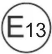
| Certifications | E13 |
| Optional Accessories | Infrared remote control, sun visor for M55L or M75L |
Frequently Asked Questions - PerfectView RVS 755W DOMETIC
User questions about PerfectView RVS 755W DOMETIC
0 question about this device. Answer the ones you know or ask your own.
Ask a new question about this device
Download the instructions for your Rear Camera in PDF format for free! Find your manual PerfectView RVS 755W - DOMETIC and take your electronic device back in hand. On this page are published all the documents necessary for the use of your device. PerfectView RVS 755W by DOMETIC.
USER MANUAL PerfectView RVS 755W DOMETIC
Please read this instruction manual carefully before installation and first use, and store it in a safe place. If you pass on the product to another person, hand over this instruction manual along with it.
Table of contents
1 Explanation of symbols. 8
2 Safety and installation instructions 9
3 Scope of delivery 11
4 Accessories 11
5 Intended use 12
6 Technical description 12
7 Installing the LCD monitor 14
8 Using the LCD monitor 18
9 Cleaning and caring for the LCD monitor 19
10 Warranty 19
11 Disposal. 19
12 Technical data 20
1 Explanation of symbols

CAUTION!
Safety instruction: Failure to observe this instruction can lead to injury.

NOTICE!
Failure to observe this instruction can cause material damage and impair the function of the product.

NOTE
Supplementary information for operating the product.
2 Safety and installation instructions
Please observe the safety instructions and stipulations issued by the vehicle manufacturer and service workshops.
The manufacturer accepts no liability for damage in the following cases:
- Faulty assembly or connection
- Damage to the product resulting from mechanical influences and excess voltage
- Alterations to the product without express permission from the manufacturer
- Use for purposes other than those described in the operating manual

NOTICE! Beware of damage
- To prevent the risk of short circuits, always disconnect the negative terminal of the vehicle's electrical system before working on it. If the vehicle has an additional battery, its negative terminal should also be disconnected.
- Inadequate supply cable connections could result in short circuits, causing:
- C a b l e f i r e s
- The airbag being triggered
- Damage to electronic control equipment
- Electrical malfunctions (indicators, brake light, horn, ignition, lights)
Therefore, please observe the following instructions:
-
When working on the following cables, only use insulated cable terminals, plugs and flat sockets:
-
30 (direct supply from positive battery terminal)
- 15 ( c o n n e c t e d p o s i t i v e t e r minal, behind the battery)
- 31 (return cable from the battery, earth)
-58 (reversing light)
Do not use porcelain wire connectors.
- Use a crimping tool (fig. 1 12, page 2) to connect the cables.
-
Screw the cable when connecting cable 31 (earth)
-
Screw on the cable using a cable terminal and serrated washer to one of the vehicle's earth bolts or
- Screw the cable to the bodywork using a cable terminal and a self-tapping screw
Make sure there is a good earth connection.
If you disconnect the negative terminal of the battery, all data stored in the volatile memories will be lost.
-
The following data must be reset, depending on the vehicle equipment options:
-
R a d i o c o d e
- Vehicle clock
- T i m e r
- On-board computer
- Seat position
You can find instructions for making these settings in the operating manual.
Observe the following installation instructions:

CAUTION!
- Secure the monitor in such a way that it cannot become loose under any circumstances (sudden braking, accidents) and cause injuries to the occupants of the vehicle.
- Do not attach the monitor in the air bag deployment path, as this could cause injury if the airbags are triggered.
Observe the following instructions when working with electrical parts:
- When testing the voltage in electrical cables, only use a diode test lamp (fig. 1, page 2) or a voltmeter (fig. 2, page 2).
Test lamps with a bulb (fig. 1 3, page 2) consume voltages which are too high and can damage the vehicle's electronic system.
-
When routing the electrical connections, ensure that:
-
They are not kinked or twisted
- They do not rub on edges
- They are not laid in sharp-edged ducts without protection (fig. 3, page 3).
Insulate all connections.
- Secure the cables against mechanical wear by using cable binders or insulating tape, for example on existing cables.
Observe the following instructions when handling the LCD monitor:

CAUTION!
- People (including children) whose physical, sensory or mental capacities or whose lack of experience or knowledge prevent them from using this product safely should not use it without the supervision or instruction of a responsible person.
- Do not open the monitor (fig. 4, page 3).
- Do not submerge the monitor in water (fig. 5, page 3); the monitor is not waterproof.
- The monitor must not impair your vision when driving (fig. 8, page 4).
- Do not operate the monitor with wet hands.
- Do not operate the monitor if the housing has been damaged.

NOTICE!
- Connect it to the correct voltage.
-
Do not use the monitor in areas which
-
Are subjected to direct sunlight,
- Are subject to strong temperature fluctuations,
- Have high levels of humidity,
- Are poorly ventilated,
-
Are dusty or oily.
-
Do not press against the LCD display.
- Do not drop the monitor.
- If you use the monitor in vehicles, the vehicle should be running during operation to prevent the vehicle battery from discharging.
The picture quality can be impaired in the vicinity of electromagnetic fields.
For this reason do not mount the monitor near loudspeakers.
3 S C O P E O F D E I
No. in
fig. 9,
page 4
Quantity Description
Ref. no.
M55LM75L
1 Monitor 9600000061 9600000062
21 Monitor bracket 9102200193
31 Monitor bracket cover
- 1 Connection cable 9102200195
Fastening material
4 Accessories
Available as accessories (not included in the scope of delivery):
| Description | Ref. no. |
| IR remote control | 9102200199 |
| Sun visor for M55L | 9102200200 |
| Sun visor for M75L | 9102200201 |
The LCD monitors PerfectView M55L (ref. no. 9600000061) and M75L (ref. no. 9600000062) are monitors which are primarily intended for use in vehicles. They can be used together with cameras (e.g. a reversing video system) or other video sources.
The LCD monitors are designed for use in all vehicles.
The LCD monitor are designed for leisure use.
6 Technical description
6.1 Function description
The LCD monitor can be connected to cameras (e.g. reversing video systems) or other video sources (e.g. DVD players). It is possible to switch back and forth between video sources.
The monitor features control cables which allow the cameras to be activated automatically.
It can operate up to three cameras.
It can be used with a RAM mount.
6.2 Control elements
The following control elements are located on the monitor:
| No. in fig. 10, page 5 | Descrip- tion | Description |
| 1 Sensor window for the dimmer function. The brightness of the display is automatically adapted to the ambient light. | ||
| 2 Switches the monitor on and off. The button lights up red when the monitor is in standby. It lights up green when the monitor is switched on. | ||
| 3 + 1. Increases the brightness. 2. Increases the value of the selected parameter if a menu is opened. | ||
| 4 - 1. Reduces the brightness. 2. Reduces the value of the selected parameter if a menu is opened. | ||
| 5 | : | 1 . S w |
| 2. Calls up the parameters for setting. The parameters are distributed over four screen pages in the following order: Page 1: Picture - B r i g h t n e s s - C o n t r a s t - C o l o u r - V o l u m e - A u t o D i m | ||
| Page 2: Options - Language: German, English, French, Italian, Dutch, Spanish, Portuguese, Russian - Camera 1/Camera 2/Camera 3: Normal or Mirrored - Sensitivity: Setting of the switching threshold for the night dimmer function | ||
| Page 3: Default - Default: Default setting for all parameters | ||
| 6 CAM | Switches from one camera to the next. | |
| 7 | M o n i | |
| 8 | Loudspeaker | |
7 Installing the LCD monitor
7.1 Tools required (fig. 1, page 2)
For installation and assembly you will need the following tools:
- Measuring ruler (4)
- Centre punch (5)
Hammer(6) - Drill head set (7)
- Drill (8)
Screwdriver(9)
To establish and test the electrical connection, the following tools are required:
- Diode test lamp (1) or voltmeter (2)
Insulating tape (10) - Heat shrinking sleeve
Hot air blower (11)
Crimping tool (12) - Soldering iron (optional) (13)
- Solder (optional) (14)
- Cable bushing sleeves (optional)
To fasten the cables you may require additional cable binders.
7.2 Installing the monitor

CAUTION! Beware of injury
Select the location of the monitor so that it cannot injure the passengers in the vehicle under any circumstances (e.g. sudden braking, road traffic accidents).
Observe the following installation instructions:
- Select an installation location that provides an unobstructed view of the monitor (fig. 6 and fig. 7, page 3).
- Never install the monitor in areas where your head could hit it or in the airbag deployment path. This could cause injury if the airbag opens.
- The monitor must not impair your vision when driving (fig. 8, page 4).
- The installation location should be flat.
- Check that there is sufficient space underneath the installation location to attach the washers and nuts.
- Check beforehand that there is sufficient space on the other side for the drill head to come out (fig. 2, page 3).
- Bear in mind the weight of the monitor. Provide reinforcement if necessary (larger washers or plates).
- Make sure you can lay the connection cable to the monitor.
Choosing the installation location (fig. 11, page 6)
Place the monitor on the monitor bracket.
Position the monitor and the attached monitor bracket provisionally.
Mark the outlines of the corners of the support base on the dashboard.
Take the monitor off the monitor bracket.
Screwing the monitor bracket onto the dashboard (fig. 12, page 6)
Hold the support base within the outlines marked beforehand.
Fasten the monitor bracket with the self-tapping screws.
Fastening the monitor
Set the monitor on the monitor bracket and secure it with the knurled nut (fig. 11, page 6).
▶Slide the cover over the monitor bracket on the monitor.
7.3 Connecting the monitor electrically
The circuit diagram for the LCD monitor can be found in fig. 14, page 7:
| No. Description | |||||||
| 1 | M | o | n | i | t | o | r |
| 2 | 2 | 0 | - | p | i | n | s |
| 3 Monitor line | |||||||
| 4 20-pin plug | |||||||
| 5 | 12-24 V positive cable (red): connected to the positive pole of the ignition (connected positive, terminal 5) or the positive pole of the battery (terminal 30). | ||||||
| 6 Earth cable (black): connected to the negative pole of the voltage source. | |||||||
| 7 Cable (green): control input for video input CAM1, such as for connecting the reversing light | |||||||
| 8 Cable (white): control input for video input CAM2, such as for the side camera | |||||||
| 9 6-pin CAM1 socket (connection to video source 1) | |||||||
| 10 6-pin CAM2 socket (connection to video source 2) | |||||||
| 11 6-pin CAM3 socket (connection to video source 3), with video signal detection) | |||||||

NOTICE!
Cables and connections that are not properly installed will cause malfunctions or damage to components.
Correct installation of cables and connections ensures lasting and trouble-free operation of the retrofitted components.
Observe the following instructions when laying the connection cable:
- If possible, use original ducts for laying the cables, or other suitable options, such as ventilation grilles. If there are no existing ducts, you must drill a hole of 22 mm . Check beforehand that there is sufficient space on the other side for the drill head to emerge (fig. 2 , page 3).
- Cover the holes with the feed through (fig. 12 1, page 6) in the base of the monitor bracket.
- To prevent damage to the cables, when laying them ensure that there is always sufficient distance to vehicle components which can become hot (lights, heaters, ventilators etc.).
-
When laying the cables (fig. 3, page 3), make sure:
-
They are not kinked or twisted
- They do not rub on edges
- They are not laid in sharp-edged ducts without protection.
Connecting the monitor as a reversing video system (fig. 14, page 7)
Lay the connection cable for the monitor bracket on the dashboard.
Insert the plug of the monitor cable (2) into the socket (4) of the connection cable (3).
Wait until you hear the plug snap in.

NOTICE! Beware of damage
Make sure the polarity is correct when connecting to a voltage source.
Connect the red and black cables of the connection cable to a suitable voltage supply:
- Connect the red cable (5) to terminal 15 (ignition).
- Connect the black cable (6) to terminal 31 (earth).
If the monitor is to be activated when reverse gear is selected, connect the green cable (7) to the positive cable of the reversing light.

NOTE
If voltage is present in the green cable (7), the reversing camera will be activated automatically. The reversing camera has priority.
If the monitor is to be activated e.g. when the indicator is flashing, connect the following control cable to a positive cable of the indicator:
- white cable (8)

NOTE
If voltage is present in this control cable, the video input CAM2 will be activated.
This control cable is used as a signal cable for the activation of a side camera when an indicator is flashing, for example.
If necessary, connect the CAM1 socket (9) of the connection cable to the plug of the video source 1 (e.g. side camera).
If necessary, connect the CAM2 socket (10) of the connection cable to the plug of video source 2 (e.g. camera).

NOTE
Observe the power consumption of the video system. The cameras are equipped with heaters. A maximum current of 1.5 A can flow (three cameras in heating mode). Use a disconnector switch for direct connection to the battery. This allows you to disconnect the video system from the battery easily if you are no longer using the vehicle.
Connection for a reversing camera
If necessary, connect socket CAM3 (11) of the connection cable to the plug of the additional reversing camera.
8 Using the LCD monitor
8.1 Switching on the monitor
If the monitor is switched off, press the button (fig. 10 2, page 5) to switch the monitor on.
The button lights up green.
The picture appears.
8.2 Switching off the monitor
Press the button (fig. 10 2, page 5) to switch off the monitor.
The button lights up red.
The picture disappears.
8.3 Setting the monitor
To set the monitor to suit your requirements, proceed as follows (fig. 10, page 5):
Press the " " button (5) to call up the required parameter.
The parameters to be set appear in the following order:
Page 1: Picture
- B r i g h t n e s s : 0
- 1 0 0
- C on t r a s t : 0
- 1 0 0
- C o l o u r : 0
- 1 0 0
- Vol u m e : 0
- 1 0 0
- Auto Dim On, Off
Page 2: Options
- Language: German, English, French, Italian, Dutch, Spanish, Portuguese, Russian
- Camera 1/Camera 2/Camera 3: Normal or Mirrored
Sensitivity: 1, 2
Setting of the switching threshold for the night dimmer function to avoid glare.
In dimming mode, the switching threshold can be set at two levels.
Page 3: Default
- Reset ("Default"): Default setting for all parameters
Press the "+" button (3) or the "-" button (4) to set the required parameter.
Press the "+" button (3) to increase the value of the selected parameter.
Press the - button (4) to reduce the value of the selected parameter.
8.4 Setting the video source
Proceed as follows to set the video source (fig. 10, page 5):
If you would like to switch to a different video source, press the "CAM" button (6).
The monitor changes the camera in the order "Camera 1 - Camera 2 - Camera 3".
8.5 Detecting the trailer camera
This function is required when using a trailer camera (fig. 13, page 6) if the system is activated automatically via the reverse gear.
- One camera connected (e.g. vehicle without a trailer): the camera connected to CAM1 (1) is activated.
- Two cameras connected (e.g. vehicle with a trailer): the camera connected to CAM3 (2) is activated (CAM1 is inactive; CAM1 can only be activated via the "CAM" button)
9 Cleaning and caring for the LCD monitor

NOTICE! Beware of damage
- Do not use sharp or hard objects for cleaning, as these may damage the monitor.
- Remove the cable before cleaning the monitor to prevent short circuiting.
Clean the monitor with a soft, damp cloth from time to time.
10 Warranty
The statutory warranty period applies. If the product is defective, please contact the manufacturer's branch in your country (see the back of the instruction manual for the addresses) or your retailer.
For repair and guarantee processing, please send the following items:
Defect components
- A copy of the receipt with purchasing date
- A reason for the claim or description of the fault
11 Disposal
Place the packaging material in the appropriate recycling waste bins wherever possible.

If you wish to finally dispose of the product, ask your local recycling centre or specialist dealer for details about how to do this in accordance with the applicable disposal regulations.
12 Technical data
| M55L M75L | ||
| Ref. no.: 9600000061 96000000062 | ||
| Type: Colour TFT LCD | ||
| Display size: 5" (12.7 cm) 7" (17.8 cm) | ||
| Brightness: approx. 350 cd/m2 Approx. 400 cd/m2 | ||
| Display resolution, H x V: 385 000 pixels | ||
| Video standard: PAL/NTSC (automatic switching) | ||
| Operating voltage: | 12 - 30 V== | |
| Power: | Max. 10 W | |
| Operating temperature: | -20 °C to 70 °C | |
| Storage temperature: | -25 °C to 80 °C | |
| Humidity: | Max. 85 % | |
| Vibration resistance: | 6 g | |
| Dimensions in mm W x H x D: | 146 x 87 x 26 | 190 x 110 x 26 |
| Weight: | 350 g 400 g | |
Approvals
The device has E13 certification.
6 Description technique
N. in fig.10, vagina 5
Denominazione
Descrizione
- Telecamera1/Telecamera2/Telecamera3 ("Camera1/Camera2/Camera3"): "Normale" o
$$ " I m m a g i n e s p e c u l a r e" $$
8.3 Stalla in monitor
He INCIOJIb3yIte KJEMMOBbie KOJODKN.
- Д�� coeditorнaya ka6epeи nCnoB3yIte o6xHmHbIe Kneu (pnc. 1 12, ctp. 2).
-
Ппвntte ka6eь ри coeHneHnx K npoBody 31 (kopnyc)
-
C NOMOUIKabenbHOrO 3axnMa n 3y6aToN npyxHHoN 7a86bl K BnHTy dIra CoeINHeHnC KOpnyCOM, IMeIOUeMycr Ha aBTOMOBnne nn
-
спомошью кабениного 3aximaиcamohape3aIOUeRO BVNTa
ObepeuBaIe xopoWee coeHHeHne c Kopnycom!
Pn OTcoeHHeHH KJIeMMbl OTPuataTeIbHO rONIOca aKKyMylTOpHO 6aTapeN Bce 3Hepro3aBNCMbIe 3aONOMHaIOUne yCTpOJCTBa 3NeKTPoHNKn CnCTem KOMopOpTa TepaHT COXpaHeHHbE B HIX DaHHbIe.
B 3aBnCIMOCTN OT OCHaUeHnA BTOMO6nI, Bam pnpTeTc 3aHOBO HAcTpOB cNeDyUoHne daHHbE:
| Наменованne | Apr. № |
| ИК дисс韫шке упавлике | 9102200199 |
| С С С С С С C C C C C C C C C C C C C C C C C C C C C C C C C C C C C C C C C C C C C C C C C C C C C C C C C C D A B C D E F G H I J K L M N O P Q R S T U V W X Y Z A B C D E F G H I J K L M N O P Q R S T U V W X Y Z A B C D E F G H I J K L M N O P Q R S T U V W A B C D E F G H I J K L M N O P Q R S T U V W A B C D E F G H I J K L M N O P Q R S T U V W A B C I J K L M N O P Q R S T U V W A B C I J K L M N O P Q R S T U V W A B C I J K L M N O P Q R S T U W A B C I J K L M N O P Q R S T U W A B C I J K L M N O P Q R S T U W A B C I J K L M N O P Q R S U V W A B C I J K L M N O P Q R S U V W A B C I J K L M N O P Q R S U V W A B C I J K L M N O P Q R S T U V W A B C I J K L M N O P Q R S T U V W A B C I J K L M N O F G H I J K L M N O F G H I J K L M N O F G H I J K L M N O F G H I J K L M N O F G H I J K L M N O F G HR S T U V W A B C I J K L M N O F G H I J K L M N O F G H I J K L M N O F G H I J K L M N O F G H I j k l m n O F G H I j k l m n O F G H I j k l m n O F G H I j k l m n O F G H I j k l m n O F G H I j k l m u v w x y z A B C D E F G H I j k l m n O F G H I j k l m u v w x y z A B C D E F G H I j k l m u v w x y z A B C D E F G H I j k l m u v w x y z A B C D E F G H I j k l m u v w z A B C D E F G H I j k l m u v w z A B C D E F G H I j k l m u v w z A B C D E F G H I j k l m u ν ν ν ν ν ν ν ν ν ν ν ν ν ν ν ν ν ν ν ν ν ν ν ν ν ν ν ν ν ν ν ν ν ν ν ν ν ν ν ν ν ν ν ν ν ν ν ν ν ν V A B C D E F G H I j k l m u ν ν ν ν ν ν ν ν ν ν ν ν ν ν ν ν ν ν ν ν ν ν ν ν ν ν ν ν ν ν ν ν ν ν ν V A B C D E F G H I j k l m n O F G H I j k l m n O F G H I j k l m n O F G H I j k l m n O F G H I j k l m n О F G H I j k l m n О F G H I j k l m n О F G H I j k l m n О F G H I j k l m n О F G H I j k l m n O F G H I j k l m n О F G H I j k l m n О F G H I j k l m n О F G H I j k l m n O F G H I j k l m n O F G H I j k l m n O F G H I j k l m n O F G H I j k l m n Ο F G H I j k l m n Ο F G H I j k l m n Ο F G H I j k l m n Ο F G H I j k l m n Ο F G H I j k l m n O F G H I j k l m n O F G H I j k l m n O F G H I j k l m n O F G H I j k l m n Ф F G H I j k l m n Ф F G H I j k l m n Ф F G H I j k l m n Ф F G H I j k l m n Ф F G H I j k l m n О F G H I j k l m n О F G H I j k l m n О F G H I j k l m n О F G H I j k l m n Ф F G H I j k l m n О F G H I j k l m n О F G H I j k l m n О F G H I j k l m n O F G H I j k l m n Ф F G H I j k l m n О F G H I j k l m n О F G H I j k l m n О F G H I j k l m n Ф F G H I j k l m n O F G H I j k l m n О F G H I j k l m n О F G H I j k l m n О F G H I j k l m n Ф F G H I j k l m n Ф F G H I j k l m n О F G H I j k l m n О F G H I j k l m n Ф F G H I j k l m n О F G H I j k l m n Ф F G H I j k l m n О F G H I j k l m n Ф F G H I j k l m n Ф F G H I j k l m n Ф F G H I j k l m n Ф F G H I j k l m n O F G H I j k l m n Ф F G H I j k l m n Ф F G H I j k l m n Ф F G H I j k l m n О F G H I j k l m n Ф F G H I j k l m n Ф F G H I j k l m n О F G H I j k l m n Ф F G H I j k l m n О F G H I j k l m n О F G H I j k l m n Ф F G H I j k l m n Ф F G H I j k l m n Ф F G H I j k l m n |
6.1 OnscaHne pa60tbi
KK-MOHHTOP-3TO MOHHTOP, K KOTOPOMy MOXHO NOKIIOHTb KaMepbl (HaPnMep, BInDeOCNCTeMb3aHrero 063opa) nIN dpyrIe nCToUHKn BInDeocnHaNoB (HaPnMep, DVD-npeep).Bo3MoXHo nepeKnIOueHne Tya n O6paTHO MExdY nCToUHkAmn BInDeocnHaNoB.
MOnHTop npednaraet ynpabnnoiue nHHN, c NOMOuKOtOpbIX MOxHO aBTOMaTnueckn aKTHBnPOBaT KaMepbl.
MoHInTop MoXeT pa6OtaTb C TpeMra KaMepaMn.
OH NOIROTOBNEH DnI NcNoIb3OBaHnC KPOHHTeHOM RAM Mount.
6.2 Oprahby npbaHnna
HaMOHTopeIIMEIoTcSneDyIOUneOpraHbIynpaBnHeNia:
7 MoHTaX KK-MOHHTopa
7.1 Tpe6yemblnHcTpymeHT (pnc. 1, ctp. 2)
Дя yctaHOBKN MOHTaxa Tpe6yeTc sJeIouuH INCTpyMeHt:
-Пинэніка (4)
- Kephep (5)
- Monotok (6)
KoMnneKt cBepn (7)
- DpeB (8)
- OTPka (9)
Дял ektpueckoro noKIOUeHЯ n ero npOBepKn Tpe6yIOTc cneDyUOuNe BCnOMOraTeNbHbIe CpeICTBa:
-Дионая кОHTpoьная пamna (1) ИпВОЛьтметр (2)
- 130яционная лeNTa (10)
TepmoycadoHbI pyKaB
- PpomblneHHbIeH (11)
- O6xHmHbIe KNeuN (12)
-При n3BecTHbIX o6CToTeJIbCTBaX, naJIbHnK (13)
-Прии3BecTHbIXO6CToTeJIbCTBaX,ОIOBЯHHbI npHNoi (14)
- Pn Heo6xOIMocTn, npoxoHbIe Btyn Ka6eJr
Дя КpenenneKa6eNe MoIyT noTppe6oBaTbCra TaKxe Ka6eNbHbIe CTaXKN.
7.2 MoHTax MOHTopa

OCTOPOXHO! Onachoctb TpaBMnpoBaHna!
BbI6epnte MeTo dnn MOHITopa TaK, UTO6bl Hn np KaKnx ycNoBnX (HaPpIMep, pe3KOM TopMOxehn, aBapn) He BO3HnKaAna ONaCHOCTb TpaBMnpOBaHn NaCCaxnPOB.
Pn moTaxe co6IouaIte cneDuOuIe yka3aHna:
- Bыберпге пиюдhoe мсето мон taxa, obecneунbaюшee 6ecnpenЯтCTBeHHьо63op MOHITOPa (pnc. 6 n pnc. 7,ст. 3).
He KpeHnTe MOHITOp B 30He COyIaPeHNr C rOIOBOr nnn B paDnUcE DeNCTBnHaDyBbIX NODyWeK 6e3OnaChOCTn. B npOTnBHOM cnyae npn cpaBaHnN IMeetcR ONaCHOCTb TpaBMnPOBaHnR. - MoHITOp He DoIxKeH OrpaHnUHbTb BnIMocTb npu ynpaBneHn aBTOMo6HJem (pnc. 8, ctrp. 4).
- MecTo MOHTaxaДОЛЖHO 6bItb POBHbIM.
- Y6eIITecb B TOM, UTO IOD Bbl6paHHbIM MeCTOM MOHTaJa IMeETcB CBO6OdHoe IpocTpaHCTBO, Heo6xOdImOe dnn yCTaHOBKn 7aJ6 n raeK.
- Ппебаритбно поверьte, ИмeeТСЯДОCTaTOUHc CBO6OДHOrO MeCTa ДЯ BbIXOda CBepna (pnc. 2 ,ст. 3).
- YuHTbIbAaTe BeC MoHITopa. Ipn Heo6xOaMocTn, npedyCMOTpTe ycIneHne (60nbHne NOKnaHbIe 7aBb Hnn PAACTINbI).
- Y6eIHTecb B TOM, YTO MOXHO IPOJOKHTb Ka6eIb K MOHITOPY.
Onpepeene Mecta MOHTaxa (pnc. 11, ctp. 6)
YCTAHOBITE MOHITOP Ha KPOHHTeH.
Дяпpo6ы paCNoIoxTe MOHITOP C yCTaHOBNeHHOn OONOpO KPOHSTeHa.
Pa3MeTbTe KOHTypbl OCHOBaHnKPOHtTeHa Ha naHeI np6OpOB.
CHIMITE MOHITOP C KPOHHTeHa.
PnBnHvBaHne KpOHTeHa MOHTopa K nAHeI np6opob (pnc. 12, ctp. 6)
YctaHOBInTe onOpy KPOHHTeHa B npedeJax paHee pa3MeYeHHbIX KOHTypOB.
3aKpeNTe KPOHHTeH MOHITopa CaMOHaPe3aIOUIMN BINTaMn.
KpenneHne MOHNTopa
YCTaHOBHTe MOHITOp Ha KPOHHTeH N 3aΦHKCnpyTe ero raIKo C HakaTKo (pnc.11, cTp.6).
BdINHbTe KpbIiKU HaI KPOHHTeHOM B MOHITOP.
7.3 Θлктуескoe поКюуне моннtopа
Cxema coeHHen K-MOHHTopa npBedeHa ha pnc. 14, ctp.7.
Pn npncoeHHeH N K nCTOuHky HnprXeHna 3a npabNbHOCTbIO nonpHOCTn.
PpncoeHnHTe KpaChbI N cepHbI Ka6eNcoeHNHTeNbHO Ra6eN K NOxOJaMeMy nCTOuHky HaPjXeHna:
-ПрсоeINHInTeКраньKa6eJIb(5)K3axmMy15(3axnraHne).
-Прсоeннte черькавь (6) к зжиму 31 (kopnyс).
Ecn MoHITOp DoJxeh 6bIb aKTHBnPoBaH npn BKnIOueHn nepeaun 3aHero BXOda, To npncoeHHte 3eHbN Ka6enb (7) KnooHTeNBHomy npOBdy apbl 3aHero XOda.

YKA3AHNE
Korda Ha 3eHbI Ka6enb (7) nOaETcHa npJxHne, To aKTINBnpyETcKaMepa 3aHero Bnda. Kamepa 3aHero Bnda nMeet npOpntet.
Ecnn MoHnTOp DoJxeh 6bItb aKTHBnPoBaH, HapnpMeR, npn BKnIOueHn yKa3aTeNei NOBOPota, To npncOeDHHte CneIyUoUsn ynpabNIAUoUsn Ka6eNb K NOnOxHTeNbHOMy npOBdy yKa3aTeNei NOBOPota:
-6eIbI K a 6eIb (8)

YKA3AHNE
KordaHa 3ToT ynpabnIounn Ka6eNb PoJaETc HapjxHne, To aKTbNpyetc BnDeOBXoD CAM2.
3TOT ynpabnnoi Ka6enb cnxNt nnHne CnHaHn3aun, HApnmep, Ira aKTHBnPOBaHn 6OKOBo KaMepb npn BKnUoyehn yKa3aTepe nOBopoTa.
Pn Heo6xOaHmocTn, coeHNHe rHe3do CAM1 (9) coeHNHTeNbHO rKa6eYr CO uTeKePOM nCTouHnKa BnDeOcHnHaHa 1 (HaNPmep, 6OKOBn KaMepbl).
Ipn Heo6xOaIMocTn, coeHHTe rHe3do CAM2 (10) coeHHTeIbHOrKa6eYco uTekepom nCTouHnKa BndeOcHnHa 2 (Ha npImep, KaMepbl).

YKA3AHNE
YuHTbIbAaTe BeHnHy ToKa, Notpe6nREMO BnDEOCnCTeMoN. KaMepbIO OChaueHb HArpeBaTeMaM. MoXeTey Tok CnOi He Bblwe 1,5 A (TpN KamepbB pexHme o6o- rpeBa). Ipn HeNoCpeDCTBeHHOM npncOeHNHeH N KaKKymJrTOpHO J batapee nCnONb3yIne pa3beHNHTeB. Cero nOMoUbIO MOxHO neKo N 6bICTpo OTcoEHNHTb BVdeocnCTemy ot 6aTapeN, ecn aBTOMo6Hnb He 6yDet nCNOb3OBaTcRdNtEnbHOe Bpemr.
Подкlioочи Камерbl 3адhero o63opa
При Heo6xOaHMoCTn, coeHHTe rHe3do CAM3 (11) coeHHTeBHOrKa6eYra co 7TeKePOM dONOHHTeBHOJ KaMepbI 3aHero o63opa.
9 yxodn ounctka KK-mOHNTopa

BHIMAHHE! Onachoctb nobpeXdHnra!
dometic.com/sales-offices


