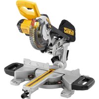
DE7400 - Saw DEWALT - Free user manual and instructions
Find the device manual for free DE7400 DEWALT in PDF.

User questions about DE7400 DEWALT
0 question about this device. Answer the ones you know or ask your own.
Ask a new question about this device
Download the instructions for your Saw in PDF format for free! Find your manual DE7400 - DEWALT and take your electronic device back in hand. On this page are published all the documents necessary for the use of your device. DE7400 by DEWALT.
USER MANUAL DE7400 DEWALT
You have chosen a DEWALT tool. Years of experience, thorough product development and innovation make DEWALT one of the most reliable partners for professional power tool users.
Technical Data
DE7400
Length mm 910
Height mm 830
Maximum working load kg 68
Weight kg 15.5
Definitions: Safety Guidelines
The definitions below describe the level of severity for each signal word. Please read the manual and pay attention to these symbols.

DANGER: Indicates an immmently hazardous situation which, if not avoided, will result in death or serious injury.

WARNING: Indicates a potentially hazardous situation which, if not avoided, could result in death or serious injury.

CAUTION: Indicates a potentially hazardous situation which, if not avoided, may result in minor or moderate injury.
CAUTION: Used without the safety alert symbol indicates a potentially hazardous situation which, if not avoided, may result in property damage.
Denotes risk of electric shock.

Denotes risk of fire.
Declaration of Conformity
DE7400
DEWALT declares that this product described under "technical data" have been designed in compliance with applicable technical rules.
For more information, please contact DEWALT at the following address or refer to the back of the manual.
The undersigned is responsible for compilation of the technical file and makes this declaration on behalf of DEWALT.

Horst Grossmann
Vice President Engineering and Product Development
DEWALT, Richard-Klinger-Straße 11, D-65510, ldstein, Germany
04.08.08

WARNING: For your own safety, read the table saw instruction manual before using any accessory. Failure to heed these warnings may result in personal injury and serious damage to the table saw and the accessory. When servicing this tool, use only identical replacement parts.
SAVE ALL WARNINGS AND INSTRUCTIONS FOR FUTURE REFERENCE
General Safety Instructions for Table Saw Accessories

WARNING: To reduce the risk of personal injury:
- Ensure all stand fasteners are securely fastened and that all stand mechanisms are in proper working order before operating the table saw.
DO NOT exceed the weight this stand can hold. The DE7400 table saw stand is designed to support 68 kgs. (150 lbs.) safely in a work environment. It is unsafe to climb, sit or stand on the stand. - Follow the mounting instructions carefully. Fasten the tool to the saw mounting brackets securely as instructed.
DO NOT modify or use stand for operations for which it is unintended.
ENGLISH
DO NOT use the stand on uneven
surfaces. DO NOT use the stand with the legs folded and stand sitting on the ground. The stand is designed to be used on a flat, stable surface.
Legs
Beams
Locator clip
Handle
Handle lock
m. Rubber bumpers
n. Kickstand
o. Tube plugs
Package Contents
The package contains:
1 Stand
2 Carriage head bolts
2 Mounting brackets
4 M8 lock nuts
2 Wheels
1 Rear axle
2 Rubber bumpers
2 M4 screws
4 Washers
2 M4 lock nuts
1 Kickstand assembly
2 Tube plugs
M6 screws (4)
M4 hex wrench
Saw mounting hardware:
4 hex head bolts
8 washers
4 nuts
4 lock washers
1 Instruction manual
- Check for damage to the tool, parts or accessories which may have occurred during transport.
Take the time to thoroughly read and understand this manual prior to operation.
Description (fig. 1A, 1B)

WARNING: Never modify the accessory or any part of it. Damage or personal injury could result.
NOTE: Figure 1B shows the front of the DE7400.
a. Axle
b. Leg supports
c. Wheels
d. Saw mounting bracket
e. Bracket release levers
f. Leg release levers
g. Locking pins
INTENDED USE
This rolling table saw stand is designed for use with DEWALT DW744 and DW745 table saws only. If you have any problem with alignment or mounting, consult an authorised DEWALT repair agent.
DO NOT use under wet conditions or in presence of flammable liquids or gases.
DO NOT let children come into contact with the tool. Supervision is required when inexperienced operators use this tool.
ASSEMBLY
Attaching the Wheels and Axle (fi g. 1, 2)
- Attach the axle (a) to the leg support (b) by aligning the pre-drilled holes. Ensure the long end of the axle is to the rear of the stand as shown. Secure axle to leg support using two carriage bolts, washers and lock nuts provided.
- Place the wheels (c) on the axle and secure with washers and lock nuts as shown. Tighten wheel and axle nuts securely.
Attaching the Kickstand (fi g. 3-5)
Insert the tube plugs (o) into the end of the kickstand (n). The groove in the tube plug should be facing down as shown. Be sure that the holes (p) in the tube plugs are in line with the holes (q) in the kickstand tube before inserting the tube plugs.
Insert the kickstand (n) through the holes in the leg support (b) on the wheel-axle side of the stand. Be sure the kickstand is pointing up when the stand is an upright position. Secure the kickstand to the beams (i) with the four M6 screws provided.
The hex wrench may be stored in the end of the tube plug as shown for future use.
Attaching the Rubber Bumpers (fi g. 6)
Attach the two rubber bumpers (m) to the handle side leg support as shown using the screws and lock nuts provided.
Table Saw Bracket Mounting (fi g. 7-10)
WARNING: To reduce the risk of injury, turn unit off, disconnect machine from power source before assembling the table saw to the table saw stand. An accidental start-up can cause injury.
WARNING: For your own safety, read and understand the table saw instruction manual before using. Failure to heed these warnings may result in personal injury and serious damage to the table saw and the accessory.
WARNING: The saw mounting brackets provided with this stand are equipped with lever locks. To reduce the risk of injury, DO NOT modify the mounting bracket lever locks.
- Unfold the legs (h) by depressing the leg release levers (f). Rotate the legs until the locking pin (g) clicks into its detent (r).
- Turn the stand upright. The stand should be stable and should not rock.
WARNING: Be sure that the locking pins have engaged and the legs are firmly held in place.
IMPORTANT: The mounting brackets MUST be attached with the arrows facing the front of the stand as shown in figure 1B.
- The locator clip (j) keeps the saw from sliding left or right during cutting operations and during transport. Install the mounting brackets on to the beam as shown by engaging the concave front lip of the mounting bracket with the rounded front edge of the beam. One of the brackets must engage the locator clip (j). The mounting bracket release levers (e) must be positioned to the rear of the stand as shown.
- Measure the distance between the mounting holes of the table saw. Position the second mounting bracket onto the beam at this distance from the first mounting bracket.
-
Align the holes in the table saw base with the slots in the saw mounting brackets (d).
-
Feed a hex head bolt with flat washer installed through each of the four holes in the table saw base and mounting brackets. Secure each location with a flat washer, lock washer and nut provided.
WARNING: To reduce the risk of personal injury, be sure the table saw is fully anchored on the stand.
WARNING: The table saw must be positioned on the tool mount so that all four corners can be bolted to the mounting brackets. If the saw is mounted properly, the mounting brackets will be positioned perpendicular to the stand rail when the saw is placed on the stand.
For additional questions or clarification on the above instructions, consult an authorised DEWALT repair agent.
To Detach the Saw from the Stand (fi g. 11, 12)
WARNING: To reduce the risk of injury, turn unit off, disconnect machine from power source before detaching the table saw from the table saw stand. An accidental start-up can cause injury.
The saw mounting brackets included with the DE7400 stand are equipped with rubber feet that can support the saw when cutting on a work area without a stand.
TO REMOVE THE SAW FOR CARRYING OR FOR USE WITHOUT THE STAND
- Reach around the sides of the saw and grasp the release levers (e).
- Pull up slightly to clear the beam and tilt the saw toward you to carry.
TO REATTACH THE SAW AND SAW MOUNTING BRACKETS TO THE STAND
- Grip the table saw table as shown while facing the front of the saw.
- Position the left-hand side mounting bracket into the locator clip.
- When the front concave lip of both mounting brackets are engaged with the front round edge of the beam, pivot the saw back and down allowing the release levers (e) to click into place on the rear beam. Rock the saw gently to verify the mounting brackets are locked onto the beams.
ENGLISH
- If the handle (k) has been extended, pull the handle lock (l) down to release the handle and then slide the handle in for storage or saw usage.
TO ATTACH DEWALT DW745 TABLE SAW TO SAW MOUNTING BRACKETS
- Remove the front feet bolts and the front rubber feet from the DW745 table saw.
- Remove the rear feet from the rear frame bar of the saw.
- Retain these components for future use.
- Feed a hex head bolt with flat washer installed through each of the four holes in the frame bars where the removed front and rear feet were previously installed. Secure each location with a flat washer, lock washer and nut provided.

WARNING: To reduce the risk of personal injury, NEVER use the table saw with the handle extended. An extended handle creates an unsafe work area.

IG: To reduce the risk of personal injury, do not hang objects from the handle. The stand may tip when downward force is applied.
Transporting the Saw on the Stand (fi g. 13)
COLLAPSING THE STAND FOR TRANSPORT
- Place one hand under the leg support (b) and hold the legs (h) slightly off the ground.
- Depress the leg release lever (f) with the other hand then push the leg under the beam on the stand. Repeat the operation on the second leg of the stand and rest the stand on wheels.
- Repeat with the other end of the stand.
- Pull the extendable handle (k) out of the side of the stand. The spring-loaded handle lock (l) will lock the handle into position for transporting the saw on the stand. Pull the handle lock down to release the handle and then slide the handle in for storage.
WARNING: To reduce the risk of personal injury, DO NOT operate the table saw mounted to the stand with the legs folded and the stand sitting on the ground.

WARNING: To reduce the risk of personal injury, DO NOT attempt to store the stand - with or without the saw attached - in a vertical position. Loss of control may result.
To Raise Stand from Collapsed Position
Roll the stand to the workspace. Be sure the area is flat and stable before attempting to set up the saw and stand.
- Tilt up the stand until the saw is at a 45-degree angle.
- Depress the leg release levers one at a time to release the locking pins and pull the front legs out until each locking pin clicks into the detent.

WARNING: Be sure that the locking pins have engaged and the legs are firmly held in place.
- Rest the stand on the legs.
- Depress the handle lock (l) to release the handle. Slide the handle (k) into the leg support (b) for storage as you work.
- Go to the opposite side of the stand and grasp the saw under the rear axle. Lift the saw and stand.
- Reach under the stand and, one at a time, depress the leg release levers to release the locking pins. Pull out the remaining two legs. Be sure that the locking pins have engaged and the legs are firmly held in place. Rest the stand on the ground.
MAINTENANCE
Your DEWALT accessory has been designed to operate over a long period of time with a minimum of maintenance. Continuous satisfactory operation depends upon proper tool care and regular cleaning.

IG: To reduce the risk of injury, turn unit off, disconnect machine from power source before detaching the table saw from the table saw stand. An accidental start-up can cause injury.
Optional Accessories

WARNING: Since accessories, other than those offered by DEWALT, have not been tested with this product, use of such accessories with this tool could be hazardous. To reduce the risk of serious injury, place stand on flat, stable surface.
DO NOT create unstable conditions.
Consult your dealer for further information on the appropriate accessories.
Protecting the Environment

Separate collection. This product must not be disposed of with normal household waste.
Should you find one day that your DEWALT product needs replacement, or if it is of no further use to you, do not dispose of it with household waste. Make this product available for separate collection.

Separate collection of used products and packaging allows materials to be recycled and used again. Re-use of recycled materials helps prevent environmental pollution and reduces the demand for raw materials.
Local regulations may provide for separate collection of electrical products from the household, at municipal waste sites or by the retailer when you purchase a new product.
DEWALT provides a facility for the collection and recycling of DEWALT products once they have reached the end of their working life. To take advantage of this service please return your product to any authorised repair agent who will collect them on our behalf.
You can check the location of your nearest authorised repair agent by contacting your local DEWALT office at the address indicated in this manual. Alternatively, a list of authorised DEWALT repair agents and full details of our after-sales service and contacts are available on the Internet at: www.2helpU.com.
GUARANTEE
30 DAY NO RISK SFACTION GUARANT
If you are not completely satisfied with the performance of your DEWALT tool, simply return it within 30 days, complete as purchased, to the point of purchase, for a full refund or exchange. Proof of purchase must be produced.
- ONE YEAR FREE SERVICE CONTRACT
If you need maintenance or service for your DEWALT tool, in the 12 months following purchase, it will be undertaken free of charge at an authorised DEWALT repair agent. Proof of purchase must be produced. Includes labour and spare parts for Power Tools. Excludes accessories.
- ONE YEAR FULL WARRANTY
If your DEWALT product becomes defective due to faulty materials or workmanship within 12 months from the date of purchase, we guarantee to replace all defective parts free of charge or, at our discretion, replace the unit free of charge provided that:
The product has not been misused.
- Repairs have not been attempted by unauthorised persons.
Proof of purchase date is produced. This guarantee is offered as an extra benefit and is additional to consumers statutory rights.
For the location of your nearest authorised DEWALT repair agent, please use the appropriate telephone number on the back of this manual. Alternatively, a list of authorised DEWALT repair agents and full details on our after-sales service are available on the Internet at www.2helpU.com.
ESPANOL
30 JOURS D'ENGAGEMENT SATISFACTION GARANTIE
Vice President Engineering and Product Development
DEWALT, Richard-Klinger-Straße 11, D-65510, Ildstein, Duitsland
04.08.08

BEWAAR ALLE WAARSCHUWINGEN EN INSTRUCTIES ALS TOEKOMSTIG REFERENTIEMATERIALAAL
WAARSCHUWING: De tafelzaag
Vice President Engineering and Product
Development
- DEWALT, Richard-Klinger-Strasse 11,
D-65510, Idstein, Germany
04.08.08

TUS: Lue poytasaahan