
HGS 55/8 Professional - Drill BOSCH - Free user manual and instructions
Find the device manual for free HGS 55/8 Professional BOSCH in PDF.

User questions about HGS 55/8 Professional BOSCH
0 question about this device. Answer the ones you know or ask your own.
Ask a new question about this device
Download the instructions for your Drill in PDF format for free! Find your manual HGS 55/8 Professional - BOSCH and take your electronic device back in hand. On this page are published all the documents necessary for the use of your device. HGS 55/8 Professional by BOSCH.
USER MANUAL HGS 55/8 Professional BOSCH
OBJ_BUCH-2568-1007 book Page 1 Thursday, August 18, 2016 11:18 AM
natural_image
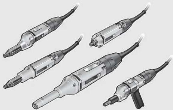
Illustration of five different types of industrial welding torches with metal and black components (no text or symbols)Robert Bosch Power Tools GmbH
70538 Stuttgart
GERMANY
www.bosch-pt.com
1609 92A 36H (2015.08) AS / 473 EURO

1 609 92A 36H
HGS
0 602 207 ... | 0 602 208 ... | 0 602 209 ... | 0 602 210 ... | 0 602 211 ...
0 602 238 ... | 0 602 245 ... | 0 602 226 ... | 0 602 227 ... | 0 602 228 ... |
0602229...|0602233...

BOSCH
text_image
Technical diagram of a drill bit with numbered parts and close-up detail view0 602 226 ..., 0 602 227 ...
text_image
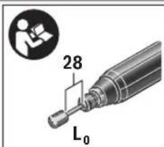
28 L₀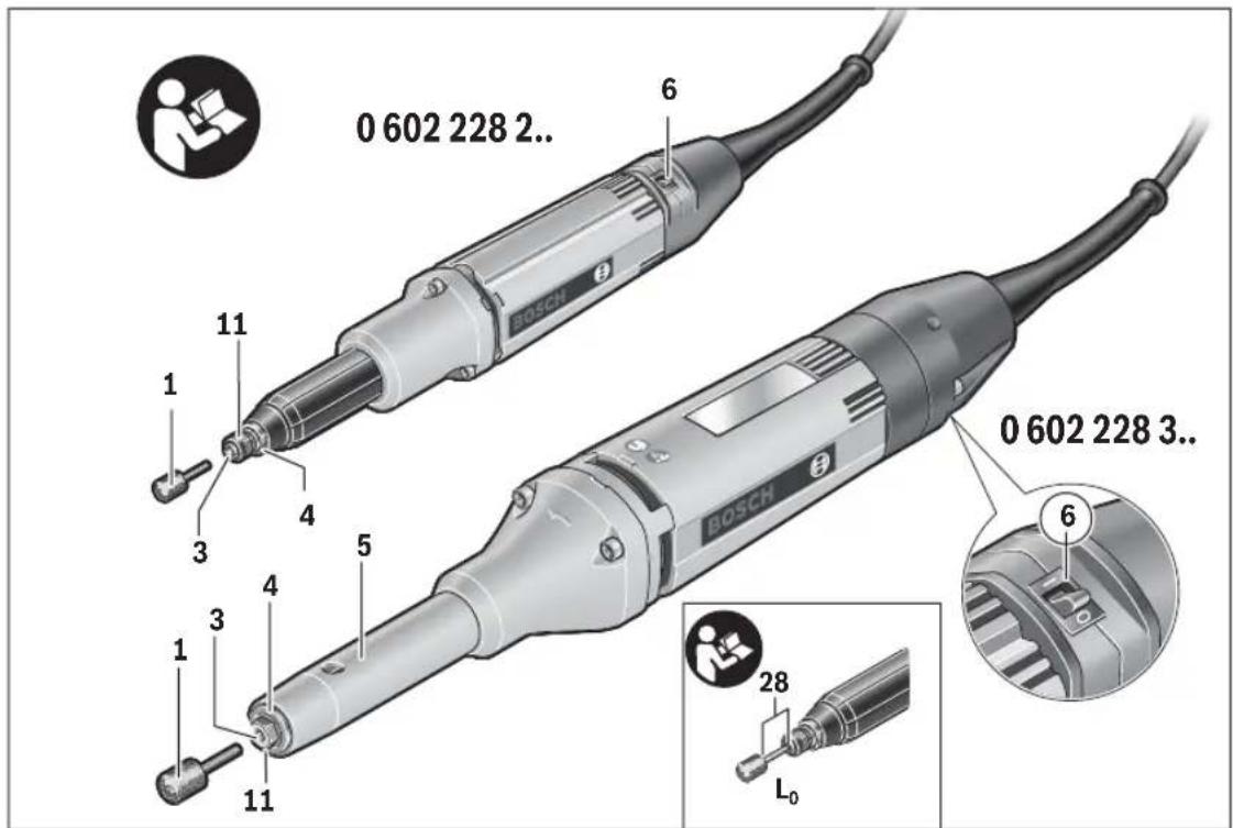
text_image
0 602 228 2.. BOSCH 11 1 3 4 5 1 3 4 11 6 0 602 228 3.. BOSCH 6 28 L₀
text_image
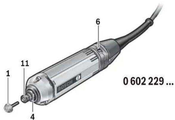
1 11 4 6 0 602 229 ...

text_image
0 602 233 ... 1 3 4 21 6
8
text_image
G 22 23 24 25 21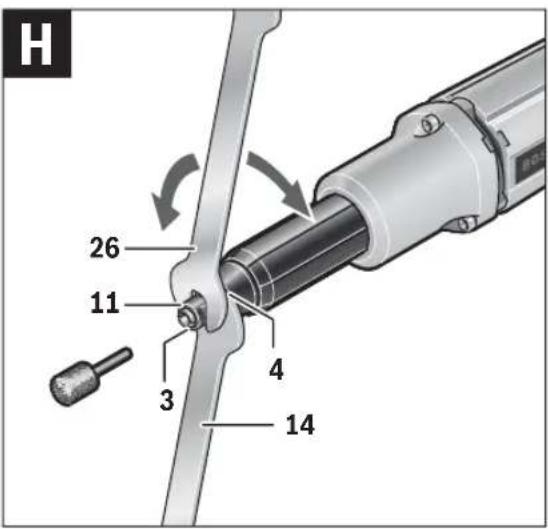
text_image
H 26 11 3 4 14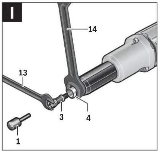
text_image
1 13 14 3 4 1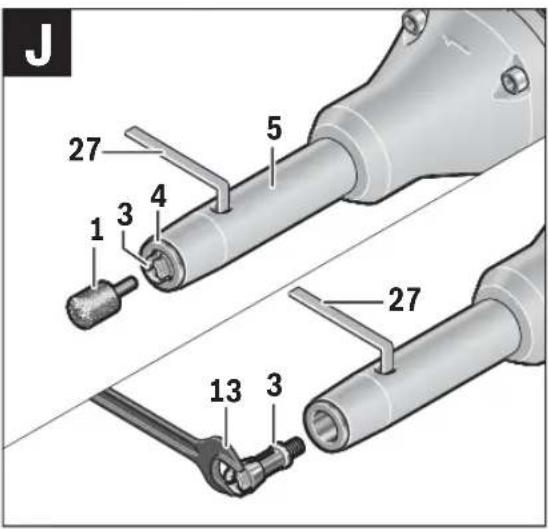
text_image
J 27 5 1 3 4 27 13 3Deutsch | 9
Deutsch
Sicherheitshinweise
Henk Becker Executive Vice President Engineering
Helmut Heinzelmann Head of Product Certification PT/ETM9
faw Sea i.v. h.w.
Robert Bosch Power Tools GmbH 70538 Stuttgart, GERMANY Stuttgart, 01.01.2017
Montage
General Power Tool Safety Warnings

WARNING Read all safety warnings and all instructions. Failure to follow the warnings and
instructions may result in electric shock, fire and/or serious injury.
Save all warnings and instructions for future reference.
The term "power tool" in the warnings refers to your mains-operated (corded) power tool or battery-operated (cordless) power tool.
Work area safety
- Keep work area clean and well lit. Cluttered or dark areas invite accidents.
▶ Do not operate power tools in explosive atmospheres, such as in the presence of flammable liquids, gases or dust. Power tools create sparks which may ignite the dust or fumes.
▶ Keep children and bystanders away while operating a power tool. Distractions can cause you to lose control.
Electrical safety
▶ Power tool plugs must match the outlet. Never modify the plug in any way. Do not use any adapter plugs with earthed (grounded) power tools. Unmodified plugs and matching outlets will reduce risk of electric shock.
▶ Avoid body contact with earthed or grounded surfaces, such as pipes, radiators, ranges and refrigerators. There is an increased risk of electric shock if your body is earthed or grounded.
▶ Do not expose power tools to rain or wet conditions. Water entering a power tool will increase the risk of electric shock.
▶ Do not abuse the cord. Never use the cord for carrying, pulling or unplugging the power tool. Keep cord away from heat, oil, sharp edges and moving parts. Damaged or entangled cords increase the risk of electric shock.
- When operating a power tool outdoors, use an extension cord suitable for outdoor use. Use of a cord suitable for outdoor use reduces the risk of electric shock.


English | 25
▶ If operating a power tool in a damp location is unavoidable, use a residual current device (RCD) protected supply. Use of an RCD reduces the risk of electric shock.
Personal safety
Stay alert, watch what you are doing and use common sense when operating a power tool. Do not use a power tool while you are tired or under the influence of drugs, alcohol or medication. A moment of inattention while operating power tools may result in serious personal injury.
▶ Use personal protective equipment. Always wear eye protection. Protective equipment such as dust mask, non-skid safety shoes, hard hat, or hearing protection used for appropriate conditions will reduce personal injuries.
▶ Prevent unintentional starting. Ensure the switch is in the off-position before connecting to power source and/or battery pack, picking up or carrying the tool. Carrying power tools with your finger on the switch or energising power tools that have the switch on invites accidents.
Remove any adjusting key or wrench before turning the power tool on. A wrench or a key left attached to a rotating part of the power tool may result in personal injury.
▶ Do not overreach. Keep proper footing and balance at all times. This enables better control of the power tool in unexpected situations.
▶ Dress properly. Do not wear loose clothing or jewellery. Keep your hair, clothing and gloves away from moving parts. Loose clothes, jewellery or long hair can be caught in moving parts.
If devices are provided for the connection of dust extraction and collection facilities, ensure these are connected and properly used. Use of dust collection can reduce dust-related hazards.
Power tool use and care
Do not force the power tool. Use the correct power tool for your application. The correct power tool will do the job better and safer at the rate for which it was designed.
▶ Do not use the power tool if the switch does not turn it on and off. Any power tool that cannot be controlled with the switch is dangerous and must be repaired.
▶ Disconnect the plug from the power source and/or the battery pack from the power tool before making any adjustments, changing accessories, or storing power tools. Such preventive safety measures reduce the risk of starting the power tool accidentally.
▶ Store idle power tools out of the reach of children and do not allow persons unfamiliar with the power tool or these instructions to operate the power tool. Power tools are dangerous in the hands of untrained users.
- Maintain power tools. Check for misalignment or binding of moving parts, breakage of parts and any other condition that may affect the power tool's operation. If damaged, have the power tool repaired before use. Many accidents are caused by poorly maintained power tools.
▶ Keep cutting tools sharp and clean. Properly maintained cutting tools with sharp cutting edges are less likely to bind and are easier to control.
▶ Use the power tool, accessories and tool bits etc. in accordance with these instructions, taking into account the working conditions and the work to be performed. Use of the power tool for operations different from those intended could result in a hazardous situation.
Service
▶ Have your power tool serviced by a qualified repair person using only identical replacement parts. This will ensure that the safety of the power tool is maintained.
Safety Warnings for Straight Grinders
Safety Warnings Common for Grinding
This power tool is intended to function as a grinder. Read all safety warnings, instructions, illustrations and specifications provided with this power tool. Failure to follow all instructions listed below may result in electric shock, fire and/or serious injury.
This power tool is not recommended for sandpaper grinding, wire brushing, polishing and abrasive cut-off operations. Operations for which the power tool was not designed may create a hazard and cause personal injury.
Do not use accessories which are not specifically designed and recommended by the tool manufacturer. Just because the accessory can be attached to your power tool, it does not assure safe operation.
The rated speed of the grinding accessory must be at least equal to the maximum speed marked on the power tool. Grinding accessories rotating faster than their permitted speed can break and fly around.
The outside diameter and the thickness of your accessory must be within the capacity rating of your power tool. Incorrectly sized accessories cannot be adequately guarded or controlled.
The arbour size of wheels, sanding drums or any other accessory must properly fit the spindle or collet of the power tool. Accessories that do not match the mounting hardware of the power tool will run out of balance, vibrate excessively and may cause loss of control.
▶ Mandrel-mounted wheels, grinding cylinders, cutting tools or other accessories must be inserted fully into the collet or chuck. The "protrusion" or exposed part of the mandrel between grinding accessory and collet or chuck must be minimal. If the mandrel is not sufficiently clamped or the grinding accessory is too far forward, the accessory may become loose and be ejected at great speed.
Do not use a damaged accessory. Before each use inspect the accessory such as abrasive wheels for chips and cracks, sanding drum for cracks, tear or excess wear, wire brush for loose or cracked wires. If power tool or accessory is dropped, inspect for damage or install an undamaged accessory. After inspecting and installing an accessory, position yourself and bystanders


26 | English
away from the plane of the rotating accessory and run the power tool at maximum no-load speed for one minute. Damaged accessories will normally break apart during this test time.
▶ Wear personal protective equipment. Depending on application, use face shield, safety goggles or safety glasses. As appropriate, wear dust mask, hearing protectors, gloves and shop apron capable of stopping small abrasive or workpiece fragments. The eye protection must be capable of stopping flying debris generated by various operations. The dust mask or respirator must be capable of filtrating particles generated by your operation. Prolonged exposure to high intensity noise may cause hearing loss.
▶ Keep bystanders a safe distance away from work area. Anyone entering the work area must wear personal protective equipment. Fragments of workpiece or of a broken accessory may fly away and cause injury beyond immediate area of operation.
Hold the power tool only by the insulated gripping surfaces, when performing an operation where the cutting accessory may contact hidden wiring or its own connecting cable. Cutting accessory contacting a "live" wire may make exposed metal parts of the power tool "live" and could give the operator an electric shock.
▶ Always hold the tool firmly in your hand(s) during the start-up. The reaction torque of the motor, as it accelerates to full speed, can cause the tool to twist.
▶ If possible, use clamps to fix the workpiece. Never hold a small workpiece in one hand whilst operating the power tool in the other. Clamping small workpieces gives you both hands free to better control the power tool. Round workpieces such as wooden dowels, bars or pipes tend to roll away when being cut, which can cause the accessory to jam and be hurled towards you.
▶ Position the connecting cable clear of the spinning accessory. If you lose control of the power tool, the connecting cable may be cut or snagged and your hand or arm may be pulled into the spinning accessory.
▶ Never lay the power tool down until the accessory has come to a complete stop. The spinning wheel may grab the surface and pull the power tool out of your control.
▶ After changing the bits or making any adjustments, make sure the collet nut, chuck or any other adjustment devices are securely tightened. Loose adjustment devices can unexpectedly shift, causing loss of control, loose rotating components will be violently thrown.
▶ Do not run the power tool while carrying it at your side. Accidental contact with the spinning accessory could snag your clothing, pulling the accessory into your body.
▶ Regularly clean the power tool's air vents. The motor's fan will draw the dust inside the housing and excessive accumulation of powdered metal may cause electrical hazards.
▶ Do not operate the power tool near flammable materials. Sparks could ignite these materials.
▶ Do not use accessories that require liquid coolants. Using water or other liquid coolants may result in electrocution or shock.
Kickback and related warnings
- Kickback is a sudden reaction to a pinched or snagged rotating wheel, belt, brush or any other accessory. Pinching or snagging causes rapid stalling of the rotating accessory which in turn causes the uncontrolled power tool to be forced in the direction opposite of the accessory's rotation.
For example, if an abrasive wheel is snagged or pinched by the workpiece, the edge of the wheel that is entering into the pinch point can dig into the surface of the material causing the wheel to climb out or kick out. The wheel may either jump toward or away from the operator, depending on direction of the wheel's movement at the point of pinching. Abrasive wheels may also break under these conditions.
Kickback is the result of power tool misuse and/or incorrect operating procedures or conditions and can be avoided by taking proper precautions as given below.
▶ Maintain a firm grip on the power tool and position your body and arm to allow you to resist kickback forces. The operator can control kickback forces, if proper precautions are taken.
▶ Especial care when working corners, sharp edges, etc. Avoid bouncing and snagging the accessory. Corners, sharp edges or bouncing have a tendency to snag the rotating accessory and cause loss of control or kickback.
▶ Do not use a toothed saw blade. Such blades create frequent kickback and loss of control over the power tool.
▶ Always feed the accessory into the material in the same direction in which the cutting edge exits the material (the same direction in which the chips are ejected). Feeding the power tool in the wrong direction causes the cutting edge of the accessory to run out of the workpiece, which causes the power tool to be pulled in this feed direction.
▶ Always clamp the workpiece securely when using rotating files, high-speed routing bits or carbide routing bits. These accessories snag in the groove even upon slight tilting and can cause kickback. If rotating files, high-speed routing bits or carbide routing bits snag, the accessory can jump out of the groove and lead to loss of control over the power tool.
Additional safety instructions for grinding
▶ Use only wheel types that are recommended for your power tool and only for recommended applications. For example: do not grind with the side of a cut-off wheel. Abrasive cut-off wheels are intended for peripheral grinding, side forces applied to these wheels may cause them to shatter.
For threaded abrasive cones and plugs use only undamaged wheel mandrels with an unrelieved shoulder flange that are of correct size and length. Proper mandrels will reduce the possibility of breakage.


Additional safety warnings

Wear safety goggles.
▶ Use suitable detectors to determine if utility lines are hidden in the work area or call the local utility company for assistance. Contact with electric lines can lead to fire and electric shock. Damaging a gas line can lead to explosion. Penetrating a water line causes property damage or may cause an electric shock.
▶ Release the On/Off switch and set it to the off position when the power supply is interrupted, e. g., in case of a power failure or when the mains plug is pulled. This prevents uncontrolled restarting.
Do not touch abrasive wheels until they have cooled down. The discs can become very hot while working.
▶ Secure the workpiece. A workpiece clamped with clamping devices or in a vice is held more secure than by hand.
Connect the machine to a mains supply with proper earthing connection. Socket outlet and extension cable must be equipped with an operative protective conductor.
Products sold in AUS and NZ only: Use a residual current device (RCD) with a rated residual current of 30 mA or less.
Safety Warnings for the Power Supply of High-frequency Tools
The safety warnings and working instructions of the frequency converter are to be strictly observed! For detailed information, contact the manufacturer of the frequency converter.
The frequency converter must be secured with a residual current protection device when working in an environment where special protection for persons is necessary. The special protection of persons is required, for example, when working in damp rooms or with materials that can produce current-conducting dust. Not using a residual current protection device can lead to electrical shock, risk of fire, or serious injuries.
The residual current protection device should be installed in the power supply network only by a qualified electrician. Only in this manner can proper functioning be ensured.
The output voltage and frequency of the frequency converter must correspond with the data on the type plate of the high-frequency tool.
▶ Operate the power tool exclusively with a fitting plug. The CEE plug must be dimensioned for the nominal current that the power tool requires (see "Technical Data").
▶ Plug mounting and connection to the power supply is to be carried out by a qualified electrician trained in handling high-frequency tool systems.
▶ Use only original cables! Before each use, check the power tool, cable and plug for possible damage. Cables and plugs may not be repaired, but must be exchanged in order to avoid danger.
Product Description and Specifications

Read all safety warnings and all instructions. Failure to follow the warnings and instructions may result in electric shock, fire and/or serious injury.
While reading the operating instructions, unfold the graphics page for the machine and leave it open.
Intended Use
Type 0 602 207 ..., 0 602 208 ..., 0 602 209 ..., 0 602 210 ..., 0 602 211 ..., 0 602 245 ..., 0 602 226 ..., 0 602 227 ..., 0 602 228 ..., 0 602 229 ..., 0 602 233 ...
The machine is intended for grinding and deburring metal using corundum grinding accessories.
Type 0 602 238 ...
The machine is intended for light grinding applications on workpieces with hard to reach locations, e.g., in inaccessible cavities of turbines.
Applies for all types
Use only the blade guards, collet chucks and clamping nuts provided or specifically released for this power tool.
Product Features
The numbering of the product features refers to the illustration of the machine on the graphics page.
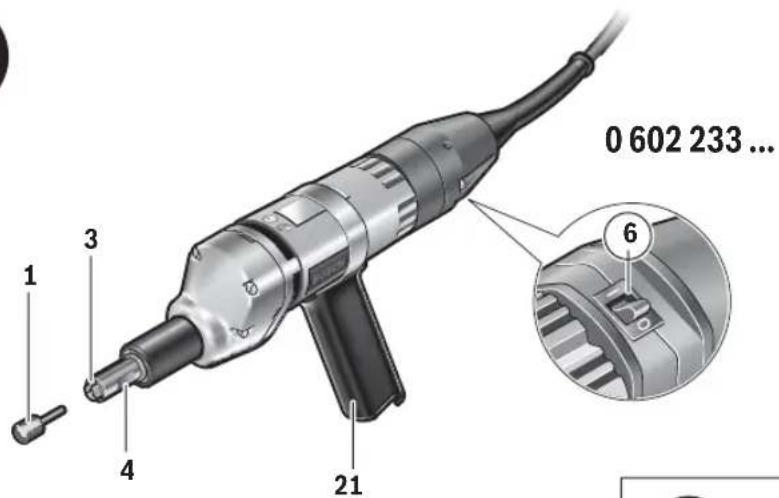
1 Grinding accessory
2 Collet of the collet chuck
3 Collet
4 Grinder spindle
5 Spindle housing
6 On/Off switch
7 Locking lever
8 Threaded sleeve
9 Grinder spindle extension
10 Open-end spanner (21 mm) on the spanner surfaces of the threaded sleeve
11 Clamping nut
12 Open-end spanner (21 mm) on the spindle housing or extension
13 Open-end spanner on the collet chuck
14 Open-end spanner on the grinder spindle
15 Cable strain relief (CEE plug)
16 Plug insert (CEE plug)
17 Screw (CEE plug)
18 Screws in plug insert 16 (CEE plug)
19 CEE plug
20 Plastic sleeve (CEE plug)
21 Auxiliary handle
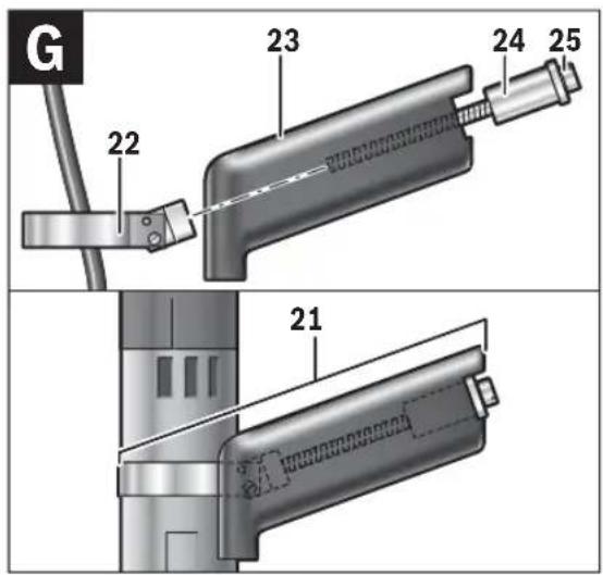
22 Tensioning strap
23 Handle


28 | English
24 Clamping holder
25 Screw inserted in clamping holder
26 Open-end spanner applied to clamping nut
27 Offset screwdriver
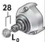
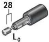
28 Inner shank dimension L_0
Accessories shown or described are not part of the standard delivery scope of the product. A complete overview of accessories can be found in our accessories program.
Notes on the Power Supply
The power tool is part of a high-frequency system and requires three-phase current with a frequency according to the type plate.
To reach this frequency, the power tool must be connected with a frequency converter (see "Connection to the Power Supply", page 36).
Technical Data
| High-frequency straight grinder | ||||
| Article number | 0 602 207 ... | 0 602 208 ... | ||
| ...407 ... 404 ... 434 | ||||
| Rated voltage | V | 7 | 2 | 135 200 |
| Frequency | Hz 200 200 300 | |||
| Rated power input | W | 6 | 0 | 0 |
| Rated power output | W | 4 | 4 | 0 |
| Nominal current | A | 5 | . | 9 |
| No-load speed | min^-1 | 23400 18300 27500 | ||
| Grinding tool diameter, max. | mm | 32 | 50 | 27 |
| Tool holder | mm | 6 | 6 | 6 |
| Weight according to EPTA-Procedure 01:2014 | kg 2.8 2.8 2.8 | |||
| Protection class | ± /1 | ± /1 | ± /1 | |
| Degree of protection | IP 20 | IP 20 | IP 20 | |
600 900
440 630
3.3 3.3
High-frequency straight grinder
| Article number | 0 602 209 ... | |||||
| ...401 | ...404 | ...407 | ...411 | ...434 | ||
| Rated voltage | V | 265 | 135 | 72 | 72 | 200 |
| Frequency | Hz | 200 | 200 | 200 | 300 | 300 |
| Rated power input | W | 600 | 600 | 600 | 900 | 900 |
| Rated power output | W | 440 | 440 | 440 | 630 | 630 |
| Nominal current | A | 1.6 | 3.3 | 5.9 | 8.8 | 3.3 |
| No-load speed | min^-1 | 12000 | 12000 | 12000 | 18000 | 18000 |
| Grinding tool diameter, max. | mm | 50 | 50 | 50 | 50 | 50 |
| Tool holder | mm | 6 | 6 | 6 | 6 | 6 |
| Weight according to EPTA-Procedure 01:2014 | kg | 2.9 | 2.9 | 2.9 | 2.9 | 2.9 |
| Protection class | ± /1 | ± /1 | ± /1 | ± /1 | ± /1 | |
| Degree of protection | IP 20 | IP 20 | IP 20 | IP 20 | IP 20 | |

High-frequency straight grinder
| Article number | 0 602 210 ... | ... 434 |
| Rated voltage | V | 200 |
| Frequency | Hz | 300 |
| Rated power input | W | 900 |
| Rated power output | W | 630 |

1 609 92A 36H | (8.11.16) Bosch Power Tools


English | 29
High-frequency straight grinder
| Nominal current A | 3 | , | |
| No-load speed | min^-1 | 4700 | |
| Grinding tool diameter, max. | mm 50 | ||
| Tool holder | mm | 6 | |
| Weight according to EPTA-Procedure 01:2014 | kg 2.8 | ||
| Protection class | ± /I | ||
| Degree of protection | IP 20 |
High-frequency straight grinder
| Article number | 0 602 211 ... | |||||
| ...401 | ...404 | ...407 | ...411 | ...434 | ||
| Rated voltage | V 265 135 72 72 200 | |||||
| Frequency | Hz 200 200 200 300 300 | |||||
| Rated power input | W 950 950 950 1450 1450 | |||||
| Rated power output | W 700 700 700 1050 1050 | |||||
| Nominal current | A | 2 | . | 8 | 5.5 10.0 15.2 | 5.5 |
| No-load speed | min^-1 | 12000 | 12000 | 12000 | 18000 | 18000 |
| Grinding tool diameter, max. | mm | 50 | 50 | 50 | 50 | 50 |
| Tool holder | mm | 8 | 8 | 8 | 8 | 8 |
| Weight according to EPTA-Procedure 01:2014 | kg | 5.4 | 5.4 | 5.4 | 5.4 | 5.4 |
| Protection class | ± /I | ± /I | ± /I | ± /I | ± /I | |
| Degree of protection | IP 20 | IP 20 | IP 20 | IP 20 | IP 20 | |
High-frequency straight grinder
| Article number | 0 602 238 ... | |||
| ... 104 | ... 107 | ... 134 | ||
| Rated voltage | V | 135 | 72 | 200 |
| Frequency | Hz | 200 | 200 | 300 |
| Rated power input | W | 400 | 400 | 600 |
| Rated power output | W | 270 | 270 | 400 |
| Nominal current | A | 3.3 | 6.0 | 3.3 |
| No-load speed | min^-1 | 12000 | 12000 | 18000 |
| Grinding tool diameter, max. | mm | 50 | 50 | 50 |
| Tool holder | mm | 6 | 6 | 6 |
| Weight according to EPTA-Procedure 01:2014 | kg | 2.2 | 2.2 | 2.2 |
| Protection class | /I | /I | /I | |
| Degree of protection | IP 20 | IP 20 | IP 20 | |
High-frequency straight grinder
| Article number | 0 602 245 ... | ... 034 |
| Rated voltage | V | 200 |
| Frequency | Hz | 300 |
| Rated power input | W | 1800 |
| Rated power output | W | 1500 |
| Nominal current | A | 6.4 |
Bosch Power Tools 1 609 92A 36H | (8.11.16)
30 | English
High-frequency straight grinder
| No-load speed min | -1 | 18000 |
| Grinding tool diameter, max. | mm 40 | |
| Tool holder– S p i n d l e | M14 | |
| Weight according to EPTA-Procedure 01:2014 | kg 4.8 | |
| Protection class | /I | |
| Degree of protection | IP 20 |
| High-frequency straight grinder | HGS 55/25 | HGS 55/25 | HGS 55/25 | HGS 55/50 | HGS 55/50 | |
| Article number 0 602 ... | ... 226 201 | ... 226 204 | ... 227 204 | ... 228 201 | ... 228 204 | |
| Rated voltage | V 265 135 200 265 135 | |||||
| Frequency | Hz 200 200 300 200 200 | |||||
| Rated power input | W 260 260 400 260 260 | |||||
| Rated power output | W 150 150 230 150 150 | |||||
| Nominal current | A | 0 | . | 9 | 1.7 1.7 0.9 1.7 | |
| No-load speed | min ^-1 | 30500 30500 29500 12000 12000 | ||||
| Grinding tool diameter, max. | mm 25 25 25 50 50 | |||||
| Spanner size of - cl a m p i n g n u t | mm | 17 | 17 | 17 | 17 | 17 |
| - gr i nd e r s p i n d l e | mm | 17 | 17 | 17 | 17 | 17 |
| Tool holder - Collet chuck | mm | 6 | 6 | 6 | 6 | 6 |
| Weight according to EPTA- Procedure 01:2014 | kg | 2.0 | 2.0 | 2.0 | 2.1 | 2.1 |
| Protection class | ± /I | ± /I | ± /I | ± /I | ± /I | |
| Degree of protection | IP 20 | IP 20 | IP 20 | IP 20 | IP 20 | |
| High-frequency straight grinder | HGS 55/50 | HGS 55/50 | HGS 55/50 | HGS 55/50 | HGS 55/50 | |
| Article number 0 602 ... | ... 228 207 | ... 228 234 | ... 228 361 | ... 228 364 | ... 228 384 | |
| Rated voltage | V | 72 | 200 265 135 200 | |||
| Frequency | Hz 200 300 200 200 300 | |||||
| Rated power input | W 260 400 260 260 400 | |||||
| Rated power output | W 150 230 150 150 230 | |||||
| Nominal current | A | 3.2 | 1.7 | 0.9 | 1.7 | 1.7 |
| No-load speed | min^-1 | 12000 18000 12000 12000 18000 | ||||
| Grinding tool diameter, max. | mm 50 50 50 50 50 | |||||
| Spanner size of-clamping nut | mm | 17 | 17 | |||
| -grinderspindle | mm | 17 | 17 12 | 12 12 | ||
| Tool holder- Collet chuck | mm | 6 | 6 | 6 | 6 | 6 |
| Weight according to EPTA-Procedure 01:2014 | kg | 2.1 | 2.1 | 2.0 | 2.0 | 2.0 |
| Protection class | ± /1 | ± /1 | ± /1 | ± /1 | ± /1 | |
| Degree of protection | IP 20 | IP 20 | IP 20 | IP 20 | IP 20 | |
English | 31
| High-frequency straight grinder | HGS 55/50 | HGS 55/50 | |
| Article number 0 602 229 ... | ... 104 ... 134 | ||
| Rated voltage | V | 1 | 3 |
| Frequency | Hz 200 300 | ||
| Rated power input | W | 2 | 6 |
| Rated power output | W | 1 | 5 |
| Nominal current | A | 1 | . |
| No-load speed | min^-1 | 12000 18000 | |
| Grinding tool diameter, max. | mm 50 50 | ||
| Spanner size of-clamping nut | mm | 17 | 17 |
| -grinderspindle | mm | 17 | 17 |
| Tool holder-Collet chuck | mm 6 6 | ||
| Weight according to EPTA-Procedure 01:2014 | kg 1.5 1.5 | ||
| Protection class | ⊕ /I | ⊕ /I | |
| Degree of protection | IP 20 | IP 20 | |
| High-frequency straight grinder | HGS 55/8 | HGS 55/8 | HGS 55/8 | HGS 55/8 | |
| Article number 0 602 233 ... | ... 201 | ... 204 | ... 207 | ... 304 | |
| Rated voltage | V | 265 | 135 | 72 | 200 |
| Frequency | Hz | 200 | 200 | 200 | 300 |
| Rated power input | W | 260 | 260 | 260 | 400 |
| Rated power output | W | 150 | 150 | 150 | 230 |
| Nominal current | A | 0.9 | 1.7 | 3.2 | 1.7 |
| No-load speed | min^-1 | 50000 | 50000 | 50000 | 50000 |
| Grinding tool diameter, max. | mm | 8 | 8 | 8 | 8 |
| Spanner surface on the - collet chuck | mm | 9 | 9 | 9 | 9 |
| - gr i nd e r sp i nd le | mm | 11 | 11 | 11 | 11 |
| Tool holder - Collet chuck | mm | 3 | 3 | 3 | 3 |
| Weight according to EPTA-Procedure 01:2014 | kg | 1.7 | 1.7 | 1.7 | 1.7 |
| Protection class | /I | /I | /I | /I | |
| Degree of protection | IP 20 | IP 20 | IP 20 | IP 20 |
Noise/Vibration Information
Sound emission values determined according to EN 60745-2-23.
The vibration level given in this information sheet has been measured in accordance with a standardised test given in EN 60745 and may be used to compare one tool with another. It may be used for a preliminary assessment of exposure. The declared vibration emission level represents the main applications of the tool. However if the tool is used for different applications, with different accessories or insertion tools or is poorly maintained, the vibration emission may differ. This may significantly increase the exposure level over the total working period.
An estimation of the level of exposure to vibration should also take into account the times when the tool is switched off or when it is running but not actually doing the job. This may significantly reduce the exposure level over the total working period. Identify additional safety measures to protect the operator from the effects of vibration such as: maintain the tool and the accessories, keep the hands warm, organisation of work patterns.
32 | English
| 0602 207 ... | 0602 209 ... | 0602 211 40. | 0602 211 411 | 0602 211 434 | 0602 238 ... | 0602 245 ... | ||
| Typically the A-weighted sound pressure level of the product is | dB(A) | 78 | 78 | 76 | 79 | 79 | 71 | 79 |
| Uncertainty K= | dB | 3 | 3 | 3 | 3 | 3 | 3 | 3 |
| The noise level when working can exceed 80 dB(A). Wear hearing protection! | ||||||||
| Vibration total values a_h (triax vector sum) and uncertainty K determined according to EN 60745-2-23: Grinding surfaces (roughing): | ||||||||
| a_h | m/s2 | 4 | 4 | <2.5 | 4 | 4 | 3 | 5 |
| K | m/s2 | 3 | 3 | 1.5 | 1.5 | 1.5 | 3 | 1.5 |
| 0602 208... | 0602 210 434 | ||
| Typically the A-weighted sound pressure level of the product is | dB(A) | 79 | 79 |
| Uncertainty K= | dB | 3 | 3 |
| The noise level when working can exceed 80 dB(A). Wear hearing protection! | |||
| Vibration total values a_h (triax vector sum) and uncertainty K determined according to EN 60745-2-23: Grinding surfaces (roughing): | |||
| a_h | m/s2 | 4 | <2.5 |
| K | m/s2 | 3 | 1.5 |
| 0602 226 ... | 0602 227 ... | 0602 233 ... | 0602 228 ... | 0602 229 ... | ||
| Typically the A-weighted sound pressure level of the product is lower than Uncertainty K= The noise level when working can exceed 80 dB(A). Wear hearing protection! | dB(A) dB | 72 3 | 73 3 | Typically the A-weighted sound pressure level of the product is Uncertainty K= The noise level when working can exceed 80 dB(A). Wear hearing protection! | dB(A) dB | 71 3 |
| Vibration total values a_h (triax vector sum) and uncertainty K determined according to EN 60745-2-23: Grinding surfaces (roughing): a_h K | m/s ^2 m/s ^2 | 3 1.5 | 1 a_h 1.5 K | Vibration total values a_h (triax vector sum) and uncertainty K determined according to EN 60745-2-23: Grinding surfaces (roughing): | m/s ^2 m/s ^2 | 3 1.5 |
English | 33
Declaration of Conformity CE
We declare under our sole responsibility that the product described under "Technical Data" is in conformity with all relevant provisions of the directives 2011/65/EU, until 19 April 2016: 2004/108/EC, from 20 April 2016 on: 2014/30/EU, 2006/42/EC including their amendments and complies with the following standards: EN 60745-1, EN 60745-2-23, EN 50581.
Technical file (2006/42/EC) at: Robert Bosch Power Tools GmbH, PT/ETM9, 70538 Stuttgart, GERMANY
Henk Becker
Executive Vice President Engineering
Helmut Heinzelmann
Head of Product Certification PT/ETM9

Robert Bosch Power Tools GmbH
70538 Stuttgart, GERMANY
Stuttgart, 01.01.2017
Assembly
▶ Disconnect the power supply before making any adjustments, changing accessories, or placing the machine aside. This safety measure prevents accidental starting of the power tool.
Mounting of the Extension (see figure A) (Type 0 602 238 ...)
Depending on the application, the grinder spindle can be extended up to 450 mm. For this purpose, extension with 150 mm (article number 3 606 120 031) and 300 mm (article number 3 606 120 032) are available as an accessory.
▶ When working with an extension, the effective force on the grinder spindle must not exceed 15 N (max.)! This corresponds with a grinding-point load of 1.5 kg. Otherwise, the grinder spindle can break.
Loosening the Grinder Spindle
- Heat up the spindle housing 5 in the area of the threaded sleeve 8 to approx. 100 °C, e.g., using a hot air blower/heat gun with temperature control. Unscrew the spindle housing together with the grinder spindle using open-end spanner 12 by turning in anticlockwise direction, while counter-holding the spanner surfaces of the threaded sleeve 8 with open-end spanner 10.
Inserting an Extension
- Apply a drop of the provided Loctite 241 to the thread of the extension 9. Screw the thread of the extension into grinder spindle 4 and tighten with 20Nm .
- Pay attention that the toothing of the spindle is mounted tension-free.
- When mounting an additional extension, also apply a drop of Loctite 241 to the second extension and screw it onto the first one.
- Afterwards, apply a drop of the provided Loctite 241 to the thread of the threaded sleeve 8, screw on the extension and tighten with 20Nm .
Mounting the Auxiliary Handle
Type 0 602 233 ... (see figure G)
The auxiliary handle 21 is not mounted upon delivery of the power tool.
The auxiliary handle 21 consists of the tensioning strap 22, handle 23, clamping holder 24 and screw 25.
- Mount the auxiliary handle before connecting the machine to the power supply.
- Firstly, guide screw 25 through the opening of the clamping holder 24 and then with the clamping holder into the handle 23.
- Screw the screw into the thread on the metal handle of the tensioning strap 22. Mount the tensioning strap 22 via the cable onto the housing of the power tool and bring the handle into the right position.
- Tension the tensioning strap 22 around the housing by tightening screw 25.
- Check if the auxiliary handle 21 is seated firmly on the housing.
Changing the Tool
(Type 0 602 207 ..., 0 602 208 ..., 0 602 209 ..., 0 602 210 ..., 0 602 211 4 ..., 0 602 238 ..., 0 602 245 ...)
▶ Only use grinding points with a matching shank diameter. A grinding point/accessory with a shank diameter that does not fit the tool holder (see "Technical Data"), can not be clamped properly and will damage the collet chuck.
When inserting a grinding point/accessory, pay attention that its shank is seated tightly in the tool holder. When the shank of the grinding point/accessory is not inserted deep enough into the tool holder, the grinding point/accessory can slip out again and no longer be controlled.
▶ Do not use cut-off discs and routing accessories. The power tool does not have safety devices for these application tools.
The rated speed of the grinding point/accessory must be at least equal to the maximum speed marked on the power tool. Accessories running faster than their rated speed can break apart and be thrown about.
▶ Use only grinding points/accessories that are in perfect condition and not worn. Defective grinding points/accessories, as an example, can break apart and cause injuries or damage.
▶ After inspecting and installing the grinding point/accessory, position yourself and bystanders away from the plane of the rotating grinding point/accessory and run the power tool at maximum no-load speed for one minute. Damaged grinding points/accessories will normally break apart during this test time.


34 | English
The application tool must be clamped at least 10 mm. The inner shank dimension L_0 can be used to calculate the maximum permitted speed of the application tool from the specifications provided by manufacturer of the application tool. It must not be less than the maximum speed of the power tool.
Inserting a Grinding Point (see figure C)
The collet chuck 3, which holds the grinding point/accessory 1, is located directly on grinder spindle 4.
- Hold the grinder spindle 4 on the spanner surfaces with the open-end spanner 14.
- Loosen the collet chuck 3 with the open-end spanner 13 by turning in anticlockwise direction.
▶ Use only properly fitting and undamaged open-end spanners.
- Insert the dust-free grinding point/accessory 1 into the collet 2 of the collet chuck 3.
- Insert the clamping shaft of the grinding tool to the stop into the collet chuck 3.
- Hold the grinder spindle 4 by the spanner surfaces with open-end spanner 14 and clamp the grinding point/accessory 1 with open-end spanner 13 by turning the collet chuck 3 in clockwise direction.
Type 0 602 245 ... (see figure B): The grinding accessory must have an appropriate thread. Screw the grinding accessory onto the grinder spindle 4. Hold the grinder spindle by the spanner surfaces with the open-end spanner provided. - At first, test-run newly mounted grinding points/accessories at no-load.
Removing a Grinding Point/Accessory
CAUTION Grinding points/accessories can become hot during prolonged power tool
operation. Use protective gloves when removing grinding points/accessories.
- Loosen the collet chuck as previously described and remove the grinding point/accessory.
Changing the Collet Chuck (see figure D)
(Type 0 602 211 5..., 0 602 208 ..., 0 602 209 ..., 0 602 210 ..., 0 602 211 4., 0 602 238 ...)
- Hold the grinder spindle 4 on the spanner surfaces with the open-end spanner 14.
- Loosen the collet chuck 3 with the open-end spanner 13 by turning in anticlockwise direction.
▶ Use only properly fitting and undamaged open-end spanners. - Turn open-end spanner 13 in anti-clockwise direction until the collet chuck 3 can be removed from the grinder spindle 4.
- To mount a collet chuck, hold the grinder spindle 4 with open-end spanner 14 by the spanner surfaces, insert the collet chuck 3 into the grinder spindle and tighten it by turning open-end spanner 13 in clockwise direction.
Changing the Tool
(Type 0 602 226 ..., 0 602 227 ..., 0 602 228 ..., 0 602 229 ..., 0 602 233 ...)
▶ Only use grinding points with a matching shank diameter. A grinding point/accessory with a shank diameter that does not fit the tool holder (see "Technical Data"), can not be clamped properly and will damage the collet chuck.
When inserting a grinding point/accessory, pay attention that its shank is seated tightly in the tool holder.
When the shank of the grinding point/accessory is not inserted deep enough into the tool holder, the grinding point/accessory can slip out again and no longer be controlled.
▶ Do not use cut-off discs and routing accessories. The power tool does not have safety devices for these application tools.
The rated speed of the grinding point/accessory must be at least equal to the maximum speed marked on the power tool. Accessories running faster than their rated speed can break apart and be thrown about.
▶ Use only grinding points/accessories that are in perfect condition and not worn. Defective grinding points/accessories, as an example, can break apart and cause injuries or damage.
▶ After inspecting and installing the grinding point/accessory, position yourself and bystanders away from the plane of the rotating grinding point/accessory and run the power tool at maximum no-load speed for one minute. Damaged grinding points/accessories will normally break apart during this test time.
The application tool must be clamped at least 10 mm. The inner shank dimension L_0 can be used to calculate the maximum permitted speed of the application tool from the specifications provided by manufacturer of the application tool. It must not be less than the maximum speed of the power tool.
▶ Only use properly fitting and undamaged open-end spanners (see "Technical Data").
Type 0 602 226 ..., 0 602 227 ..., 0 602 228 2 ..., 0 602 229 ... (see figure H) Inserting a Grinding Point
- Clean the grinder spindle 4 and all parts to be mounted.
- Hold the grinder spindle 4 on the spanner surfaces with the open-end spanner 14. Loosen clamping nut 11 with open-end spanner 26 by turning in anticlockwise direction.
- Insert the clamping shaft of the grinding tool to the stop into the collet chuck 3.
- Hold the grinder spindle 4 with open-end spanner 14 and clamp the grinding accessory 1 with open-end spanner 26 by turning in clockwise direction.
The grinding tools must run completely concentrical. Do not continue to use out-of-round grinding accessories, instead, replace before continuing to work.


English | 35
▶ Do not tighten the collet chuck of the clamping nut as long as no grinding accessory is mounted. Otherwise, the collet chuck can become damaged.
At first, test-run newly mounted grinding points/accessories at no-load.
Removing a Grinding Point/Accessory
CAUTION
Grinding points/accessories can be- come hot during prolonged power tool
operation. Use protective gloves when removing grinding points/accessories.
Loosen the clamping nut as previously described and remove the grinding point.
Type 0 602 233 ... (see figure I) Inserting a Grinding Point
The collet chuck 3, which holds the grinding point/accessory 1, is located directly on grinder spindle 4.
- Clean the grinder spindle 4 and all parts to be mounted.
- Hold the grinder spindle 4 on the spanner surfaces with the open-end spanner 14. Loosen the collet chuck 3 with the open-end spanner 13 by turning in anticlockwise direction.
- Insert the clamping shaft of the grinding tool to the stop into the collet chuck 3.
- Hold the grinder spindle 4 by the spanner surfaces with open-end spanner 14 and clamp the grinding point/accessory 1 with open-end spanner 13 by turning the collet chuck 3 in clockwise direction.
At first, test-run newly mounted grinding points/accessories at no-load.
Removing a Grinding Point/Accessory
CAUTION
Grinding points/accessories can be- come hot during prolonged power tool
operation. Use protective gloves when removing grinding points/accessories.
Loosen the collet chuck as previously described and remove the grinding point/accessory.
Type 0 602 228 3.. (see figure J) Inserting a Grinding Point
- Turn the grinder spindle 4 clockwise or anticlockwise, until the slot of the eccentric bolt can be seen in the hole of the spindle housing 5.
- Insert the screwdriver blade of the offset screwdriver 27 (delivery scope) into the slot of the eccentric bolt. Turn the offset screwdriver clockwise to loosen the eccentric tension.
The collet chuck 3 is moved slightly out of the grinder spindle 4 when doing this.
- Insert the clamping shaft of the grinding tool to the stop into the collet chuck 3.
- If the grinding accessory cannot be inserted, loosen the eccentric tension more.
Using open-end spanner 13, unscrew collet chuck 3 by turning anticlockwise, while counter-holding with the offset screwdriver 27 in the slot of the eccentric bolt.
Only unscrew the collet chuck until the clamping shank of the grinding accessory can be inserted.
- Afterwards, screw in the collet chuck again with open-end spanner 13 by turning clockwise, while counter-holding with the offset screwdriver 27 in the slot of the eccentric bolt.
- Turn the offset screwdriver 27 anticlockwise, until collet chuck 3 is drawn into the grinder spindle 4.
Check if the grinding accessory is tightly seated.
At first, test-run newly mounted grinding points/accessories at no-load.
Removing a Grinding Point/Accessory

CAUTION Grinding points/accessories can be- come hot during prolonged power tool
operation. Use protective gloves when removing grinding points/accessories.
Loosen the eccentric tension and the collet chuck as previously described and remove the grinding point.
Changing the Collet Chuck
▶ Only use properly fitting and undamaged open-end spanners (see "Technical Data").
Type 0 602 226 ..., 0 602 227 ..., 0 602 228 2 ..., 0 602 229 ... (see figure H)
- Hold the grinder spindle 4 on the spanner surfaces with the open-end spanner 14.
Loosen clamping nut 11 with open-end spanner 26 by turning in anticlockwise direction. - Turn open-end spanner 26 in anticlockwise direction until the clamping nut 11 with the integrated collet chuck 3 can be removed from the grinder spindle.
- To mount a collet chuck, hold the grinder spindle 4 by the spanner surfaces with open-end spanner 14, insert the new clamping nut with integrated collet chuck into the grinder spindle, and tighten clamping nut 11 with open-end spanner 26 by turning in clockwise direction.
Type 0 602 233 ... (see figure I)
- Hold the grinder spindle 4 on the spanner surfaces with the open-end spanner 14.
Loosen the collet chuck 3 with the open-end spanner 13 by turning in anticlockwise direction. - Turn open-end spanner 13 in anti-clockwise direction until the collet chuck 3 can be removed from the grinder spindle 4.
- To mount a collet chuck, hold the grinder spindle 4 with open-end spanner 14 by the spanner surfaces, insert the collet chuck 3 into the grinder spindle and tighten it by turning open-end spanner 13 in clockwise direction.
Type 0 602 228 3.. (see figure J)
- Turn the grinder spindle 4 clockwise or anticlockwise, until the slot of the eccentric bolt can be seen in the hole of the spindle housing 5.
- Insert the screwdriver blade of the offset screwdriver 27 (delivery scope) into the slot of the eccentric bolt. Turn the offset screwdriver clockwise to loosen the eccentric tension.
The collet chuck 3 is moved slightly out of the grinder spindle 4 when doing this.


36 | English
- Using open-end spanner 13, unscrew collet chuck 3 by turning anticlockwise, while counter-holding with the offset screwdriver 27 in the slot of the eccentric bolt.
- To mount a collet chuck, insert it into the grinder spindle. Afterwards, screw in the collet chuck again with open-end spanner 13 by turning clockwise, while counter-holding with the offset screwdriver 27 in the slot of the eccentric bolt.
- Turn the offset screwdriver 27 anticlockwise, until collet chuck 3 is drawn into the grinder spindle 4.
Dust/Chip Extraction
Dusts from materials such as lead-containing coatings, some wood types, minerals and metal can be harmful to one's health. Touching or breathing-in the dusts can cause allergic reactions and/or lead to respiratory infections of the user or bystanders.
Certain dusts, such as oak or beech dust, are considered as carcinogenic, especially in connection with wood-treatment additives (chromate, wood preservative). Materials containing asbestos may only be worked by specialists.
- Provide for good ventilation of the working place.
- It is recommended to wear a P2 filter-class respirator. Observe the relevant regulations in your country for the materials to be worked.
▶ Prevent dust accumulation at the workplace. Dusts can easily ignite.
Connection to the Power Supply
For operation of the power tools, a frequency converter is required that generates three-phase current with a frequency according to that listed on the type plate.
Frequency converters are available in various sizes, with different frequencies, secondary voltages and rated outputs. The choice of the frequency converter depends on the power tools to be connected. When selecting a frequency converter, contact your Bosch-specialist shop for advice.
The machine is provided with a four meter long specialty cable without plug. To put it into operation, the specialty cable must be equipped with a four-pole CEE plug (identification colour green).
Additionally, the machine can be equipped with a commercially available motor protection switch for protection against overload. The adjustment range of the motor protection switch must cover the nominal current of the power tool (see "Technical Data"). The motor protection switch must react in less than one second.
Please observe the safety warnings and assembly instructions in the operating instructions of the motor protection switch!
Mounting the CEE Plug (see figures E - F)
- Loosen the two screws 17 and pull the plug insert 16 out of the plug housing of the CEE plug 19.
-
Cut off the plastic sleeve 20 according to the diameter of the specialty cable of the power tool and insert the specialty cable through the CEE plug housing.
-
Insert the four conductors through the cable strain relief 15.
- Loosen the four small screws 18 in the plug insert 16 and insert the conductor ferrule of the brown L1 conductor into contact tube L1, the conductor ferrule of the blue L2 conductor into contact tube L2, the conductor ferrule of the black L3 conductor into contact tube L3, and the conductor ferrule of the green/yellow conductor + into the earthing contact tube +
- Firmly tighten the four small screws 18 in the plug insert 16 to affix the conductors.
- Now, tighten the screws of the cable strain relief 15 so that the cable clamp goes around the complete cable sheath, ensuring that no pressure is on the conductor ferrules.
- Reinsert plug insert 16 into the housing of the CEE plug 19 and tighten both screws 17 again.
– Afterwards, check the proper function of the protective conductor.
- Insert the CEE plug 19 of the power tool into the connection socket of the frequency converter.
Now, connect the frequency converter to the power supply. For information on how to connect the frequency converter to the power supply, see the frequency converter operating instructions.
▶ Afterwards, check the rotation direction!
Checking the Rotation Direction
The rotation direction of the grinder spindle must correspond with the arrow on the power tool.
If the grinder spindle rotates in the wrong direction when putting into operation for the first time (see "Switching the Power Tool On/Off", page 37), switch the power tool off immediately and disconnect it from the power supply.
- Loosen the two screws 17 again and pull the plug insert 16 out of the plug housing of the CEE plug 19.
- Loosen the conductor ferrules of the black and brown conductors from their contact tubes.
- Now, insert the conductor ferrule of the black conductor L3 into contact tube L1, and the conductor ferrule of the brown conductor L1 into contact tube L3.
- Firmly tighten the small screws 18 in the plug insert 16 to affix the conductors.
- Reinsert plug insert 16 into the housing of the CEE plug 19 and tighten both screws 17 again.
- Afterwards, check the proper function of the protective conductor.
- Reconnect the power tool to the power supply.
Operation
Starting Operation
The voltage and frequency of the power source must correspond with the data on the type plate of the power tool.


English | 37
▶ Check grinding tools before using. The grinding tool must be mounted properly and be able to move freely. Carry out a test run for at least one minute with no load. Do not use damaged, out-of-centre or vibrating grinding tools. Damaged grinding tools can burst and cause injuries.
If the machine should unexpectedly stop operating even though the On/Off switch 6 is in the "On" position, set the On/Off switch to "Off". This will prevent uncontrolled restarting of the machine. Before restarting the machine, check the power supply (see "Connection to the Power Supply", page 36).
To save energy, only switch the power tool on when using it.
▶ Always connect the power tool to the frequency converter first, before connecting the frequency converter to the mains supply.
Switching the Frequency Converter On/Off
The frequency converter must be put into operation first before actuating the power tool.
For this, observe the operating instructions of the frequency converter.
Switching the Power Tool On/Off (Type 0 602 207 ..., 0 602 208 ..., 0 602 209 ..., 0 602 210 ..., 0 602 211 ..., 0 602 245 ...)
- To start the power tool, press the On/Off switch 6 forward and then down.
- To lock-on the pressed On/Off switch 6, push the On/Off switch 6 further forward.
- To switch off the power tool, release the On/Off switch 6, or when it is locked, briefly press the On/Off switch 6 and then release it.
Switching the Power Tool On/Off (Type0 602 238 ...)
- To switch on the power tool, press the On/Off switch 6 and keep it pressed during the working procedure.
- To lock the On/Off switch 6, press and hold the On/Off switch and push the locking lever 7 toward the front until it engages.
- To switch off the machine, release the On/Off switch 6.
- When the On/Off switch 6 is locked-on, press it first and then release it. The locking lever 7 automatically disengages.
Switching the Power Tool On/Off
(Type 0 602 226 ..., 0 602 227 ..., 0 602 228 ..., 0 602 229 ..., 0 602 233 ...)
To switch on the machine, flip the On/Off switch 6 to position I.
To save energy, only switch the power tool on when using it. To switch off the machine, flip the On/Off switch 6 to position 0.
Working Advice
▶ Disconnect the power supply before making any adjustments, changing accessories, or placing the machine aside. This safety measure prevents accidental starting of the power tool.
▶ Clamp the workpiece if it does not remain stationary due to its own weight.
▶ Do not strain the machine so heavily that it comes to a standstill.
▶ After heavily straining the power tool, continue to run it at no-load for several minutes to cool down the accessory.
▶ Application tools can become very hot while working. Do not touch them before they have cooled down.
▶ Protect the abrasive wheels from impacts.
Working with the Straight Grinder
The choice of the application tools, such as grinding points or flap discs, depends on the application case and area. For support on choosing the appropriate grinding accessory, please contact your Bosch specialist shop.
Optimum grinding results are achieved when the grinding tool is moved uniformly back and forth with light pressure. Pressure that is too strong reduces the performance capability of the machine and causes the grinding tool to wear more quickly.
Grinding with Grinding Point
For grinding points, the grinding medium, e.g. corundum or silicone carbide, is formed and bond with suitable bonding agents and possibly with reinforcement inlays, thus representing a grinding and load-carrying unit. During operation, both the grinding and bonding agent are "used up" evenly, whereby the size of the grinding point gradually becomes smaller.
Grinding points are particularly suitable for precision mechanical work, mould making and for deburring metal. Due to the high circumferential speed, the workpiece is subject to high heat development.
Grinding with Grinding Discs
When grinding, the best working results are achieved when the grinding disc is applied as flat as possible. Move the machine back and forth applying moderate pressure. This ensures that the workpiece does not become too hot, and is not subject to discolouration and grooves.
Maintenance and Service
Maintenance and Cleaning
▶ Disconnect the power supply before making any adjustments, changing accessories, or placing the machine aside. This safety measure prevents accidental starting of the power tool.
For safe and proper working, always keep the machine and ventilation slots clean.
In extreme conditions, always use dust extraction as far as possible. Blow out ventilation slots frequently and install a portable residual current device (PRCD).
When working metals, conductive dust can settle in the interior of the power tool. The total insulation of the power tool can be impaired.
38 | English
▶ Regularly measure the no-load speed of the grinder spindle. When the measured value is more than 10 % above or below the specified no-load speed (see "Technical Data"), have the machine checked by an authorised service agent for Bosch power tools. When the no-load speed is too high, the application tool can break; when the no-load speed is too low, the working performance is reduced.
▶ Use only original cables! Before each use, check the power tool, cable and plug for possible damage. Cables and plugs may not be repaired, but must be exchanged in order to avoid danger.
▶ Have maintenance and repair work performed only by qualified specialists. In this manner, it can be ensured that the safety of the power tool is maintained.
Clean the connection sockets, couplers and plugs of the tool, after it has been disconnected from the mains supply, using a dry, lint-free cloth and remove dust and dirt particles.
Clean the gearbox after the first 150 running hours using a mild solvent. Follow the solvent manufacturers directions for use and disposal. Lubricate the gearbox using Bosch gearbox lube. Repeat the lubrication procedure every 300 hours after the initial gearbox service.
An authorized Bosch after-sales service agent will carry out this work quickly and reliably.
If the replacement of the supply cord is necessary, this has to be done by Bosch or an authorized Bosch service agent in order to avoid a safety hazard.
Please store and handle the accessory(-ies) carefully.
Accessories
Information about the complete quality accessory program can be found on the Internet at www.bosch-pt.com and www.boschproductiontools.com or at your dealer.
After-sales Service and Application Service
Our after-sales service responds to your questions concerning maintenance and repair of your product as well as spare parts. Exploded views and information on spare parts can also be found under:
www.bosch-pt.com
Bosch's application service team will gladly answer questions concerning our products and their accessories.
In all correspondence and spare parts orders, please always include the 10-digit article number given on the nameplate of the product.
Great Britain
Robert Bosch Ltd. (B.S.C.)
P.O. Box 98
Broadwater Park
North Orbital Road
Denham
Uxbridge
UB 9 5HJ
At www.bosch-pt.co.uk you can order spare parts or arrange
the collection of a product in need of servicing or repair.
Tel. Service: (0344) 7360109
E-Mail: boschservicecentre@bosch.com
Ireland
Origo Ltd.
Unit 23 Magna Drive
Magna Business Park
City West
Dublin 24
Tel. Service: (01) 4666700
Fax: (01) 4666888
Australia, New Zealand and Pacific Islands
Robert Bosch Australia Pty. Ltd.
Power Tools
Locked Bag 66
Clayton South VIC 3169
Customer Contact Center
Inside Australia:
Phone: (01300) 307044
Fax: (01300) 307045
Inside New Zealand:
Phone: (0800) 543353
Fax:(0800)428570
Outside AU and NZ:
Phone: +61 3 95415555
www.bosch.com.au
Republic of South Africa
Customer service
Hotline: (011) 6519600
Gauteng - BSC Service Centre
35 Roper Street, New Centre
Johannesburg
Tel.: (011) 4939375
Fax:(011)4930126
E-Mail: bsctools@icon.co.za
KZN - BSC Service Centre
Unit E, Almar Centre
143 Crompton Street
Pinetown
Tel.: (031) 7012120
Fax: (031) 7012446
E-Mail: bsc.dur@za.bosch.com
Western Cape - BSC Service Centre
Democracy Way, Prosperity Park
Milnerton
Tel.: (021) 5512577
Fax: (021) 5513223
E-Mail: bsc@zsd.co.za
Bosch Headquarters
Midrand, Gauteng
Tel.: (011) 6519600
Fax: (011) 6519880
E-Mail: rbsa-hq.pts@za.bosch.com


1 609 92A 36H | (8.11.16) Bosch Power Tools


Français | 39
Disposal
The machine, accessories and packaging should be sorted for environmental-friendly recycling.
Do not dispose of power tools into household waste!
Only for EC countries:

According to the European Directive 2012/19/EU for Waste Electrical and Electronic Equipment and its implementation into national right, power tools that are no longer usable must be collected separately and disposed of in an environmentally correct manner.
Subject to change without notice.
Français
Executive Vice President Engineering
Helmut Heinzelmann
Head of Product Certification PT/ETM9

i.v. h=mc
Robert Bosch Power Tools GmbH
70538 Stuttgart, GERMANY
Stuttgart, 01.01.2017
Montage
Robert Bosch (France) S.A.S.
Executive Vice President
Head of Product Certification
Engineering
PT/ETM9

i.v. h=m
Robert Bosch Power Tools GmbH
70538 Stuttgart, GERMANY
Stuttgart, 01.01.2017
64 | Español
Montaje
Henk Becker Executive Vice President Engineering Helmut Heinzelmann Head of Product Certification PT/ETM9
jawr Sea i.v. h.wc
Robert Bosch Power Tools GmbH 70538 Stuttgart, GERMANY Stuttgart, 01.01.2017
Montagem
Henk Becker Executive Vice President Engineering Helmut Heinzelmann Head of Product Certification PT/ETM9
jaw Bao i.v. h.w.
Robert Bosch Power Tools GmbH 70538 Stuttgart, GERMANY Stuttgart, 01.01.2017
Montaggio
Executive Vice President Engineering
Helmut Heinzelmann
Head of Product Certification PT/ETM9
jaw Bo i.v. h.w.
Robert Bosch Power Tools GmbH
70538 Stuttgart, GERMANY
Stuttgart, 01.01.2017
Montage
Executive Vice President Engineering
Helmut Heinzelmann
Head of Product Certification PT/ETM9
jwr Sea i.v. h.w.
Robert Bosch Power Tools GmbH
70538 Stuttgart, GERMANY
Stuttgart, 01.01.2017
Montering
Bosch Service Center
Telegrafvej 3
2750 Ballerup
På www.bosch-pt.dk kan der online bestilles reservedele eller oprettes en reparations ordre.
Tlf. Service Center: 44898855
Fax: 44898755
E-Mail: vaerktoej@dk.bosch.com
Bortskaffelse
Executive Vice President Engineering
Helmut Heinzelmann
Head of Product Certification PT/ETM9
Jawr Beo i.V. H.W.
Robert Bosch Power Tools GmbH 70538 Stuttgart, GERMANY Stuttgart, 01.01.2017
Bosch Power Tools 1 609 92A 36H | (8.11.16)
138 | Svenska
Montage
Bosch Service Center
Telegrafvej 3
2750 Ballerup
Danmark
Tel.: (08) 7501820 (inom Sverige)
Fax: (011) 187691
Avfallshantering
Executive Vice President
Engineering
Helmut Heinzelmann
Head of Product Certification
PT/ETM9
fwr Seo i.v. h:m
Robert Bosch Power Tools GmbH
70538 Stuttgart, GERMANY
Stuttgart, 01.01.2017
Montering
Executive Vice President Engineering
Helmut Heinzelmann
Head of Product Certification PT/ETM9

i.v. h=w
Robert Bosch Power Tools GmbH 70538 Stuttgart, GERMANY Stuttgart, 01.01.2017
Suomi | 165
Asennus
Executive Vice President Engineering
Helmut Heinzelmann
Head of Product Certification PT/ETM9

i.v. h=mc
Robert Bosch Power Tools GmbH 70538 Stuttgart, GERMANY Stuttgart, 01.01.2017
Συναρμολόγηση
Executive Vice President Engineering
Helmut Heinzelmann
Head of Product Certification PT/ETM9

Robert Bosch Power Tools GmbH 70538 Stuttgart, GERMANY Stuttgart, 01.01.2017
Montaj
Executive Vice President
Engineering
Helmut Heinzelmann
Head of Product Certification
PT/ETM9
fwr 2e0 i.v. h:m
Robert Bosch Power Tools GmbH
70538 Stuttgart, GERMANY
Stuttgart, 01.01.2017
Montaž
Robert Bosch Sp. z o.o.
Executive Vice President Engineering
Helmut Heinzelmann
Head of Product Certification PT/ETM9
fwr Seo i.v. h:m
Robert Bosch Power Tools GmbH
70538 Stuttgart, GERMANY
Stuttgart, 01.01.2017
Montáž
Bosch Service Center PT
K Vápence 1621/16
692 01 Mikulov
Executive Vice President
Engineering
Helmut Heinzelmann
Head of Product Certification
PT/ETM9

i.v. h=mc
Robert Bosch Power Tools GmbH
70538 Stuttgart, GERMANY
Stuttgart, 01.01.2017
Montáž
Henk Becker Executive Vice President Engineering Helmut Heinzelmann Head of Product Certification PT/ETM9

Robert Bosch Power Tools GmbH 70538 Stuttgart, GERMANY Stuttgart, 01.01.2017
Összeszerelés
Executive Vice President
Engineering
Helmut Heinzelmann
Head of Product Certification
PT/ETM9

Robert Bosch Power Tools GmbH
70538 Stuttgart, GERMANY
Stuttgart, 01.01.2017
Сборка
Henk Becker Executive Vice President Engineering Helmut Heinzelmann Head of Product Certification PT/ETM9
fwrsec i.v. h:m
Robert Bosch Power Tools GmbH 70538 Stuttgart, GERMANY Stuttgart, 01.01.2017
Монтаж
Executive Vice President Engineering
Helmut Heinzelmann
Head of Product Certification PT/ETM9

Robert Bosch Power Tools GmbH 70538 Stuttgart, GERMANY Stuttgart, 01.01.2017
Жинау
Executive Vice President Engineering
Helmut Heinzelmann
Head of Product Certification PT/ETM9

Robert Bosch Power Tools GmbH 70538 Stuttgart, GERMANY Stuttgart, 01.01.2017
Montare
Tel. service scule electrice: (021) 4057540
Fax: (021) 4057566
E-Mail: infoBSC@ro.bosch.com
Executive Vice President Engineering
Helmut Heinzelmann
Head of Product Certification PT/ETM9

i.v. h=m
Robert Bosch Power Tools GmbH 70538 Stuttgart, GERMANY Stuttgart, 01.01.2017
334|Български
Монтиране
Executive Vice President Engineering
Helmut Heinzelmann
Head of Product Certification PT/ETM9

i.v. h=mc
Robert Bosch Power Tools GmbH
70538 Stuttgart, GERMANY Stuttgart, 01.01.2017
Монтажа
Executive Vice President Engineering
Helmut Heinzelmann
Head of Product Certification PT/ETM9

Robert Bosch Power Tools GmbH 70538 Stuttgart, GERMANY Stuttgart, 01.01.2017
Montaža
Henk Becker Executive Vice President Engineering Helmut Heinzelmann Head of Product Certification PT/ETM9
fwr Sea i.v. h.w.
Robert Bosch Power Tools GmbH
70538 Stuttgart, GERMANY
Stuttgart, 01.01.2017
Montaža
Executive Vice President
Engineering
Helmut Heinzelmann
Head of Product Certification
PT/ETM9
fawr Sea i.v. h:m
Robert Bosch Power Tools GmbH
70538 Stuttgart, GERMANY
Stuttgart, 01.01.2017
Montaža
Executive Vice President Engineering
Helmut Heinzelmann
Head of Product Certification PT/ETM9

i.v. h=w
Robert Bosch Power Tools GmbH
70538 Stuttgart, GERMANY Stuttgart, 01.01.2017
Montaž
Henk Becker Executive Vice President Engineering Helmut Heinzelmann Head of Product Certification PT/ETM9
Jawr Seo i.V. H:m
Robert Bosch Power Tools GmbH 70538 Stuttgart, GERMANY Stuttgart, 01.01.2017
Montāža
Henk Becker Executive Vice President Engineering Helmut Heinzelmann Head of Product Certification PT/ETM9

Robert Bosch Power Tools GmbH 70538 Stuttgart, GERMANY Stuttgart, 01.01.2017
Montavimas
Henk Becker Senior Vice President Engineering
Helmut Heinzelmann Head of Product Certification
PT/ETM9
Jawr Beo i.V. H.W.C
Robert Bosch Power Tools GmbH, 70538 Stuttgart, GERMANY
Stuttgart, 01.01.2017
التركيب
Senior Vice President
Engineering
Helmut Heinzelmann
Head of Product Certification
PT/ETM9


Robert Bosch Power Tools GmbH,
70538 Stuttgart, GERMANy
Stuttgart, 01.01.2017


