
HB 1320 - Cooker DOMETIC - Free user manual and instructions
Find the device manual for free HB 1320 DOMETIC in PDF.

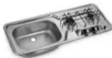
| Product type | Built-in gas hob |
| Brand | Dometic |
| Model | HB 1320 |
| Gas category | I3B/P(30) - Butane (G30) 30 mbar / Propane (G31) 30 mbar |
| Supply pressure | 30 mbar |
| Total nominal heat capacity | 2.2 kW (160 g/h) |
| Required combustion air volume | 4.4 m³/h |
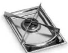
| Number of burners | 1 |
| Burner diameter | Auxiliary Ø 47 mm |
| Auxiliary burner injector | Ø 0.5 mm (stamp 50) |
| Ignition | Electronic and manual |
| Ignition power supply | 12 V DC |
| Device class | Class 3 (built-in) |
| Minimum distance to side walls | 135 mm (from the outer edge of the burner head) |
| Minimum distance above the cooking surface | 500 mm |
| Gas connection | Rigid or flexible metal hose ≤ 1.5 m |
| Cleaning | Water and soap or neutral detergent |
| Warranty | According to applicable legislation (see manual) |
Frequently Asked Questions - HB 1320 DOMETIC
User questions about HB 1320 DOMETIC
0 question about this device. Answer the ones you know or ask your own.
Ask a new question about this device
Download the instructions for your Cooker in PDF format for free! Find your manual HB 1320 - DOMETIC and take your electronic device back in hand. On this page are published all the documents necessary for the use of your device. HB 1320 by DOMETIC.
USER MANUAL HB 1320 DOMETIC
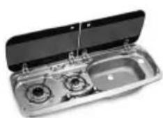
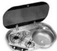
HOBS AND COMBINATIONS
HB1320 HB2370
HB3370 HBG3440
HS2320L
HS2420L HS2420R
HS2421L HS2421R
HS2460R HSG2370L
HS2460L
HSG2370R HSG2440R
HSG3430
IT
Hobs and monobloc combinations
Installation, Use, and Maintenance 29
FR
Please read this instruction manual carefully before using the appliance. If the appliance is given to another party, the instruction manual must also be provided.
Table of contents
1 Explanation of symbols 30
2 General safety instructions 30
3 Contents of supply 31
4 Intended use 31
5 Installation. 32
5.1 Installation hole 32
5.2 Gas connection 33
5.3 Electrical connections 35
5.4 Fixing 35
6 Technical description 36
6.1 Control panel 36
6.2 Burners. 37
7 Use 38
7.1 Additional safety warnings 38
7.2 Hob 39
7.3 Visual inspection of the flame 41
7.4 Gas cylinders 41
8 Cleaning and maintenance 43
8.1 Cleaning the appliance. 43
8.2 Replacing injectors 43
9 Test pressure point (if fitted) 44
10 Warranty 44
1 Explanation of symbols

CAUTION!
Security warning: Ignoring this warning could cause serious injury or death.

IMPORTANT!
Failure to observe this note can cause material damages and affect the operation of the product.

NOTE
Additional information relative to the use of the product.
Action: this symbol indicates that action is required on your part. The required action is described step-by-step.
Fig. 1 5, page 3: this information refers to an element in a figure; in this case, the figure is found in "position 5 in figure 1 on page 3".
2 General safety instructions
The manufacturer does not assume any liability for damages in the following cases:
-
damage to the product resulting from improper use
-
changes to the product without express permission from the manufacturer
-
use for purposes other than those described in the operating manual
- non-compliant installation and/or connections
This warning is located on the appliance.
- This appliance must be installed according to the regulations in force and used only in a well ventilated area.
Refer to the instructions before installing and using this appliance.
- The appliance must be installed by specialised technicians.
3 Contents of supply
Reference
Quantity Name
Fig. 1, page 2
1 Hob
2.1 Fixing screw bag (depending on
model)
1 Instructions manual
4 Intended use

CAUTION!
This appliance can only be used to cook food. Any other use is deemed incorrect and therefore hazardous. The manufacturer declines liability for damage to property and injury to persons caused by improper, incorrect or irresponsible use.
5 Installation

CAUTION!
Before installation, check that the local distribution conditions (gas type and pressure) and the settings of the appliance compatible.
The adjustment conditions for this appliance are provided on the label (or on the data plate).
This appliance is not connected to a combustion product evacuation system. It must be installed and connected in accordance with the installation rules in force. Special attention must be given to relevant ventilation governing provisions.
5.1 Installation hole

CAUTION!
The appliance should be kept away from flammable materials.
This appliance belongs to CLASS 3: APPLIANCE TO BE BUILT INTO A KITCHEN UNIT OR WORKTOP.
Minimum distances to observe from the walls (Fig. 2, page 2)
Distance Position
135 mm From the outer edge of the burner head closest to one of the side walls and/or bottom.
500 mm Between the top of the burners and the furniture or shelves present above the hob.
30 mm The distance between the bottom of the burner and the underside.
Built in hole dimensions
Depending on the model, make a hole in the cabinet as shown in Fig. 3, page 3.
The cabinet must be parallel to and flush with the horizontal worktop.
The cabinet built-in hole must be parallel. If the cabinet has aeration openings, prevent combustible materials from accessing these openings.
5.2 Gas connection

CAUTION!
Check this data before connecting the appliance to the gas cylinder. Pressure reducing valves to be used between the gas cylinder and the appliance must conform to the categories listed in the table below.
This appliance can be operated with the gases and related pressures described in the following table. The identification label glued to the appliance clearly shows the category (or categories) according to which the appliance has been adjusted.
| CATEGORY AND COUNTRIES OF DESTINATION | GAS PRESSURE | |
| I3B/P(30) | 30 mbar Butane (G30) | |
| AT BE DE DK FI GB NL NO PT SE SI | 30 mbar Propane (G31) | |
| I3+ (28-30/37) | 28-30 mbar Butane (G30) | |
| BE CH ES FR GB IE IT PT SI | 37 mbar Propane (G31) | |
| MODEL NOMINAL AND COMPLETE HEAT OUTPUT | VOLUME OF AIR REQUIRED FOR COMBUSTION | |
| kW - gr/h | m³/h | |
| HB1320 | 2.2 - 160 4.4 | |
| HB2370 | 2.8 - 204 5.6 | |
| HB3370 | 3.8 - 277 7.6 | |
| HBG3440 | 4.6 - 335 9.2 | |
| HS2320L | 2.8 - 204 5.6 | |
| HS2420L | 2.8 - 204 5.6 | |
| HS2420R | 2.8 - 204 5.6 | |
| HS2421L | 2.8 - 204 5.6 | |
| HS2421R | 2.8 - 204 5.6 | |
| HS2460L | 2.8 - 204 5.6 | |
| HS2460R | 2.8 - 204 5.6 | |
| HSG2370L | 2.8 - 204 5.6 | |
| HSG2370R | 2.8 - 204 5.6 | |
| HSG2440R | 2.8 - 204 5.6 | |
| HSG3430 | 3.8 - 277 7.6 | |

CAUTION!
During installation and connection, the gas conductor of the appliance must not be subject to twisting, pulling or other stresses.
The gas pipeline connection to the appliance must be done using a rigid metal pipe and sealing connections.
It is possible to use a hose, but it must:
- Allow for inspection at all times.
- Be protected from possible contact with heatable parts (such as the underside of the burners).
- Be protected from any stress (torsion, tensile, compression, etc.).
- Be protected from the moving parts of the cabinet (e.g. a drawer).
- Have a maximum length of 1.5 m .
- Be replaced before its expiration date.
Once connected, check the gas circuit seal by using a non-corrosive fluid to detect any leaks. Do not use a soap and water solution. DO NOT USE AN OPEN FLAME.
5.3 Electrical connections
LOW VOLTAGE 12 V=

CAUTION!
This appliance must be connected to a 12 V power pack. If a 2 × 0,5 mm² cable is used for the connection, its length must not exceed 2 meters. When wiring the appliance respect correct polarity!

CAUTION!
Never connect the appliance to the main voltage (230 V~); this would result in the ultimate destruction of the parts and a hazard to the user.
To connect the appliance, use a double cable and connect it to the terminal board identified with "+"12 V", found on the back side of the appliance. The red terminal is the positive pole, while the black terminal is the negative pole.
5.4 Fixing
Depending on the model, the appliance must be fixed to the cabinet using the screws as described in Fig. 4, page 7.
6 Technical description
6.1 Control panel
The following table shows all the buttons and symbols on the appliance.

NOTE
Buttons and symbols may vary depending on the model.
Reference
Symbol Description
Fig. 5, page 10
Indicates the control knob a hob
burner.
5 Button to actuate electronic ignition.
2 Maximum adjustment of the flame.
4 Gas turned off.
3 Minimum adjustment of the flame.
6.2 Burners
| MODEL | AUXILIARY Ø 47 mm | SEMIRAPID Ø 62 mm | RAPID Ø 77 mm | ||||||
| No. | kW | gr/h | No. | kW | gr/h | No. | kW | gr/h | |
| HB1320 | 12.2 | 160 | |||||||
| HB2370 | 1173 | 11.8131 | |||||||
| HB3370 | 2173 | 11.8131 | |||||||
| HBG3440 | 1173 | 21.8131 | |||||||
| HS2320L | 1173 | 11.8131 | |||||||
| HS2420L | 1173 | 11.8131 | |||||||
| HS2420R | 1173 | 11.8131 | |||||||
| HS2421L | 1173 | 11.8131 | |||||||
| HS2421R | 1173 | 11.8131 | |||||||
| HS2460L | 1173 | 11.8131 | |||||||
| HS2460R | 1173 | 11.8131 | |||||||
| HSG2370L | 17311 | 8131 | |||||||
| HSG2370R | 17311 | 8131 | |||||||
| HSG2440R | 1173 | 11.8131 | |||||||
| HSG3430 | 2173 | 11.8131 | |||||||
7 Use
7.1 Additional safety warnings

CAUTION!
This appliance must only be used by responsible adults. The accessible parts may be hot during and immediately after use; do not touch them and keep children away. After cooking, return the knob(s) to the closed position(s). After use, close the main gas line tap.

CAUTION!
The use of a gas cooking appliance leads to the generation of heat and moisture in the room in which it is installed. Make sure to provide good ventilation in the kitchen: keep natural ventilation openings open or install a mechanical ventilation device (mechanical extractor hood).
Intense and prolonged use of the appliance may require supplementary aeration such as the opening of a window or more effective ventilation such as an increase in the power of the possible mechanical extractor hood.
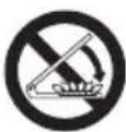
This warning is clearly shown on the glass cover of the hob. The glass covers may break if heated. Ignition of any of the burners (hob, oven and grill) must always be done with the cover raised, and always turn off all the burners (hob, oven and grill) and leave them to cool down before closing the cover.
CAUTION!
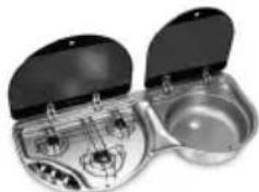
This warning refers to models with incorporated sink unit and hob and with glass lid divided between sink and hob. This warning is affixed in a visible position on the sink unit glass lid. When using the hob with the glass lid on the sink unit closed, always keep pans on hob at a distance of 10mm minimum from sink unit glass lid.
7.2 Hob
Selecting the burner

CAUTION!
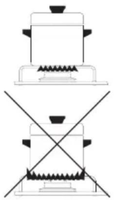
The flame must not spread over the edges of the cookware. Place the cookware centrally on the burner, so that it is stable on the support grid.
BURNER COOKWARE
DIAMETER
AUXILIARY
047mm
from 60~mm to 160~mm
SEMIRAPID
62mm
from 160mm to 220mm
RAPID
077mm
from 160 mm to 220 mm
Electronic ignition of the hob

CAUTION!
Ignition must be done without any cookware or other object on the burners.
To generate the flame, fully press down the control knob (Fig. 5 6, page 10) and turn it to the large flame position (Fig. 5 2, page 10).
Simultaneously push down the electronic ignition button (Fig. 5, page 10).
Once the flame has been generated, press the knob down for a few seconds so that the flame remains lit.

CAUTION!
If the burner does not turn on:
-
turn the knob to the small flame position (Fig. 5 3, page 10);
-
proceed with manual ignition;
- check that there is gas in the cylinder.
If the device does not work, close the gas inlet tap and contact your dealer.
Manual ignition of the hob
If the electronic ignition does not work, the manual ignition is used as a substitute.
CAUTION!
Ignition must be done without any cookware or other object on the burners.
To generate the flame, fully press down the control knob (Fig. 5 6, page 10) and turn it to the large flame position (Fig. 5 2, page 10).
Simultaneously ignite the burner with a match or gas lighter.
Once the flame has been generated, press the knob down for a few seconds so that the flame remains lit.

CAUTION!
If the burner does not turn on:
- check that there is gas in the cylinder.
If the device does not work, close the gas inlet tap and contact your dealer.
Regulating the hob flame
To adjust the flame, turn the knob to the desired position (Fig. 5 6, page 10).
7.3 Visual inspection of the flame
Depending on the type of gas used, the flame appears as follows:
- Propane (G31): flame with blue internal pin point and clear outline.
- Butane (G30): flame with slight yellow tips when igniting the burner; these tips intensify as the burner heats.
7.4 Gas cylinders

CAUTION!
The use of gas and/or a pressure different from those indicated by the manufacturer could cause irregular and incorrect operation of the appliance. The manufacturer declines all liability for the incorrect or improper use of the appliance.
The gas cylinders to be used are the most common in the country where the appliance is used. The gas to be used is clearly indicated on the outside of the packaging and on the indelible label attached on the back of the appliance. In any case, observe the following: Gas cylinders with valve and pressure reducer must be placed in an upright position and in the appropriate compartment, and access should not be impeded. Replacement of the cylinders must be performed without impediment and with ease.
Replacing the gas cylinder
Close the taps of the appliance.
Make sure no flames or fire are nearby.
Close the valve of the cylinder to be replaced.Unscrew the pressure reducer of the empty cylinder, take it out of the compartment.
Proceed in reverse order for replacement.
Check for gas leaks with the use of a non-corrosive fluid.

CAUTION!
- Do not use a soap and water solution.
- Do not use an open flame.
Turn on the burners and check for proper operation, otherwise contact an authorised technician.
CLOSE THE CYLINDER GAS SUPPLY AFTER USE.
GAS LEAKS
We recommend using a certified electronic gas leak detector.
If you smell gas:
Open the windows and immediately get all people out of the camper, caravan etc.
Never touch electrical switches, light matches or do anything that could ignite the gas.
Extinguish any open flame.
Close the cylinder valve or gas tank, and do not open the valve until the gas leak has been detected and eliminated.
Contact an authorised technician.
8 Cleaning and maintenance
8.1 Cleaning the appliance

CAUTION!
Before cleaning, switch off the appliance, disconnect it from the mains power supply and wait for it to cool down.

IMPORTANT!
Hot surfaces could be damaged if they come into contact with cold water or a damp cloth.
Do not use abrasive, corrosive, chlorine-based products, scourers or steel wool.
Do not leave acid or alkaline substances (vinegar, salt, lemon juice, etc.) on appliance surfaces.
For stainless steel surfaces and enamelled parts: wash with soap and water or mild detergent, rinse and dry. Use clean sponges and cloths.
8.2 Replacing injectors

CAUTION!
The activities must be done by authorised personnel. After this operation, we decline all liability resulting from the intervention.
The injector holder must be blocked (with the use of a tool) when removing and mounting the injectors (Fig. 6, page 10).
| BURNER Ø INJECTOR (mm) | NUMBER PRINTED ON INJECTOR | |
| AUXILIARY Ø 47 mm | 0.5 50 | |
| SEMIRAPID Ø 62 mm | 0.67 67 | |
| RAPID Ø 77 mm | 0.75 75 | |
9 Test pressure point (if fitted)
The test pressure point (pressure check valve) is fitted under the hob (Fig. 7, page 11).
Removing and mounting this test pressure point (pressure check valve) must be performed by a qualified gas service engineer. Gas pressure is related to the type of gas used to supply the appliance. Refer to chapter GAS in this manual.
10 Warranty
The statutory warranty period applies. If the product is defective, please contact the local manufacturer in your country (the address is on the back of the instruction manual) or your reference specialised dealer.
For repair and warranty processing, the following documents must be included when sending the appliance:
- a copy of the receipt showing the date of purchase;
- a reason for the claim or a description of the fault.
BASSE TENSION 12 V =

ATTENTION!
6 Description technique
NoURTJtJtJtJtJtJtJtJtJtJtJtJtJtJtJtJtJtJtJtJtJtJtJtJtJtJtJtJtJtJtJtJtJtJtJtJtJtJtJtJtJtJtJtJtJtJtJtJtJtJtJ t J t J t J t J t J t J t J t J t J t J t J t J t J t J t J t J t J t J t J t J t J t J t J t J t J t J t J t J t J t J t J t J t J t J t J t J t J t J t J t J t J t J t J t J t J t J t J t J t J t J t
RAZRED IN DRŽAVE, KJER JE V UPORABI PLINSKI TLAK
| I3B/P(30) | 30 mbar Butan (G30) |
| AT BE DE DK FI GB NL NO PT SE SI | 30 mbar Propan (G31) |
| I3+ (28-30/37) | 28-30 mbar Butan (G30) |
| BE CH ES FR GB IE IT PT SI | 37 mbar Propan (G31) |
| MODEL SKUPNA NOMINALNA TOPOLOTNA MOČ kW - g/h | POTREBNA KOLICINA ZRAKA ZA ZGOREVANJE m³/h |
| HB1320 | 2,2 - 160 4,4 |
| HB2370 | 2,8 - 204 5,6 |
| HB3370 | 3,8 - 277 7,6 |
| HBG3440 | 4,6 - 335 9,2 |
| HS2320L | 2,8 - 204 5,6 |
| HS2420L | 2,8 - 204 5,6 |
| HS2420R | 2,8 - 204 5,6 |
| HS2421L | 2,8 - 204 5,6 |
| HS2421R | 2,8 - 204 5,6 |
| HS2460L | 2,8 - 204 5,6 |
| HS2460R | 2,8 - 204 5,6 |
| HSG2370L | 2,8 - 204 5,6 |
| HSG2370R | 2,8 - 204 5,6 |
| HSG2440R | 2,8 - 204 5,6 |
| HSG3430 | 3,8 - 277 7,6 |
POZOR!
dometic.com/sales-offices


- HOBS AND COMBINATIONS
- Table of contents
- Explanation of symbols
- CAUTION!
- IMPORTANT!
- NOTE
- General safety instructions
- Contents of supply
- Intended use
- Installation
- Installation hole
- Minimum distances to observe from the walls (Fig. 2, page 2)
- Distance Position
- Built in hole dimensions
- Gas connection
- Electrical connections
- LOW VOLTAGE 12 V=
- Fixing
- Technical description
- Control panel
- Reference
- Symbol Description
- Fig. 5, page 10
- Burners
- Use
- Additional safety warnings
- Hob
- Selecting the burner
- BURNER COOKWARE
- DIAMETER
- Electronic ignition of the hob
- Manual ignition of the hob
- Regulating the hob flame
- Visual inspection of the flame
- Gas cylinders
- Replacing the gas cylinder
- CLOSE THE CYLINDER GAS SUPPLY AFTER USE.
- GAS LEAKS
- If you smell gas:
- Cleaning and maintenance
- Cleaning the appliance
- Replacing injectors
- Test pressure point (if fitted)
- Warranty
- BASSE TENSION 12 V =
- ATTENTION!
- Description technique
- POZOR!
Brand : DOMETIC
Model : HB 1320
Category : Cooker