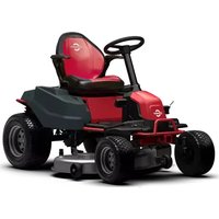
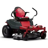
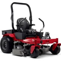
82LT107 - Lawn mower Cramer - Free user manual and instructions
Find the device manual for free 82LT107 Cramer in PDF.


| Product type | Electric ride-on lawn mower |
| Model | 82LT107 |
| Brand | Cramer |
| Rated voltage | 82 V |
| Gross weight | 106 ± 3 kg |
| Dimensions (L x W x H) | 170 x 107 x 117 cm |
| Cutting width | 107 cm |
| Cutting height range | 3.81 - 11.4 cm |
| Number of height levels | 7 |
| Forward speed | 0 - 12.9 km/h (8 mph) |
| Reverse speed | 0 - 4.8 km/h (3 mph) |
| Blade no-load speed | 2400 / 3000 / 3200 rpm |
| Blade motor power | 1.2 kW |
| Drive motor power | 1.2 kW |
| Number of blades | 2 |
| Maximum recommended slope | 15° |
| Sound pressure level | 84.77 dB(A) (K=3 dB(A)) |
| Guaranteed sound power level | 100 dB(A) |
| Vibrations (arm/body) | ≤2.5 m/s² (K=1.5 m/s²) |
| Drive tire pressure | 8 psi (0.55 bar) |
| Front caster tire pressure | 24 psi (1.65 bar) |
| Gearbox oil (type/capacity) | SAE85W-140 / 180 ml |
| Wheel nut torque | 120 Nm |
| Blade bolt torque | 90 Nm |
| Warranty (residential/commercial use) | 5 years or 1500 hours |
Frequently Asked Questions - 82LT107 Cramer
User questions about 82LT107 Cramer
0 question about this device. Answer the ones you know or ask your own.
Ask a new question about this device
Download the instructions for your Lawn mower in PDF format for free! Find your manual 82LT107 - Cramer and take your electronic device back in hand. On this page are published all the documents necessary for the use of your device. 82LT107 by Cramer.
USER MANUAL 82LT107 Cramer
DECLARATION OF CONFORMITY (UK)
Name and address of the manufacturer:
Name: Greenworks Tools Europe GmbH
Address: Brunnenweg 17, 64331 Weiterstadt, Germany
Name and address of the authorised representative:
Name: Garden Equipment Ltd
Address: First Floor, 3a Groveley Road, Christchurch, Dorset, BH23 3HB, UK
Name and address of the person authorised to compile the technical file:
Name: Simon Del-Nevo
Address: First Floor, 3a Groveley Road, Christchurch, Dorset, BH23 3HB, UK
Herewith we declare that the product
Category: Lawn Tractor
Model: 82LT107
Serial number: See product rating label
Year of Construction: See product rating label
- is in conformity with the relevant provisions of the Supply of Machinery (Safety) Regulations 2008.
- is in conformity with the provisions of the following other UK legislation:
• Electromagnetic Compatibility Regulations 2016
• The Restriction of the Use of Certain Hazardous Substances in Electrical and Electronic Equipment Regulations 2012
Furthermore, we declare that the following standard have been used:
• BS EN 62841-1, BS EN ISO 5395-1, BS EN ISO 5395-3, BS EN ISO 12100, EN ISO 14982
IEC 62321-3-1, IEC 62321-4, IEC 62321-5, IEC 62321-6, IEC 62321-7-1, IEC 62321-7-2, IEC 62321-8
Place, date:
Christchurch, Dorset, UK 10.10.2022
Signature: Ted Qu, Quality Director
Ted Qu
English
EN
1 Description......4
1.1 Overview.... 4
1.2 Control panel....4
2 Unpack the machine...... 4
3 Installation.... 5
3.1 Install the seat.... 5
3.2 Install the steering wheel....5
3.3 Install the mulch cover....5
3.4 Anti-scalp wheels.... 6
3.5 Use the app....6
4 Operating Instructions......6
4.1 Before operation....6
4.2 Operate the machine....7
5 Electrical system.... 10
5.1 Electrical system safety....10
5.2 Electrical system information....10
5.3 Digital display.... 10
6 Errors....11
6.1 Error code....12
7 Maintenance....14
7.1 Mower blade maintenance.... 14
7.2 Replace the headlight.....15
7.3 Tires....15
7.4 Lubrication....15
7.5 Torque values....16
7.6 Battery pack maintenance....16
7.7 Battery compartment filter maintenance...16
7.8 Service.... 16
8 Transportation and storage.....17
8.1 Transportation.... 17
8.2 Clean and storage....18
9 Troubleshooting...... 20
10 Technical data....22
11 Limited warranty....22
11.1 What is covered by this warranty.... 22
11.2 Who must perform the warranty service...23
11.3 What is not covered by this warranty..... 23
11.4 Disclaimer of warranty....24
11.5 Limitation of remedies.... 24
11.6 Time limit.... 24
11.7 No other warranties.... 24
11.8 Owner's responsibility....24
11.9 Allocation of risks.... 24
11.10 Warranty registration.... 24
12 EC Declaration of conformity...25
1 DESCRIPTION
1.1 OVERVIEW
See separate figure sheet 1-20
1 Seat adjustment lever 17 Steering wheel 18 Cover plate
2 Side discharge 19 Mulch cover chute
20 Bearing ring
3 Brake pedal 21 Fixation clamps
4 Control panel 22 Serial number
5 Deck height adjustment lever 23 Pairing code
6 Accelerator pedal 24 QR code
7 Parking brake handle 25 Battery compartment
8 Headlights 26 Battery
9 Cup holder 27 Battery latch
10 USB port 28 Blade
11 Anti-scalp wheels 29 Oil filling port
12 Seat panel 30 Oil drain outlet
13 Seat plug 31 Garden hose
14 Steering shaft 32 Quick coupler
15 Coupler 33 wash port
16 Steering column
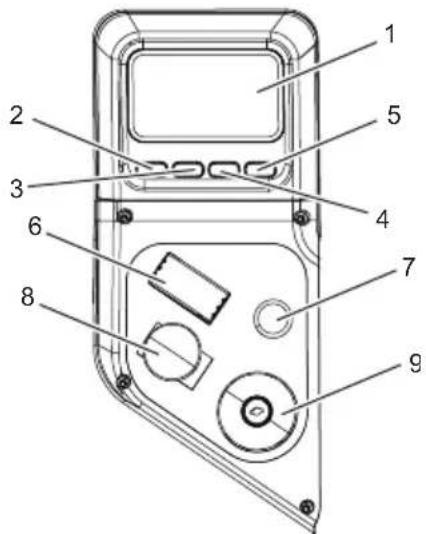
1.2 CONTROL PANEL
2 UNPACK THE MACHINE
WARNING
Make sure that you correctly assemble the machine before use.
| # | Name Function | |
| 1 | Digital display | This display shows important electrical system information. Refer to the Electrical section for complete information. |
| 2 | Blade motor speed control / Return | Adjust the blade speed (cyclic) when it's on the homepage. Press the button to return to the previous page. |
| 3 | Menu navigation / Page up | Turn the digital display to last page. Back to home screen. |
| 4 | Lamp switch / Page down | Turn on/off the lamps when it's on the homepage. Turn the digital display to the next page . |
| 5 | Cruise control button / Confirm | Push and hold over 0.4s to activate cruise control fuction, press the button to confirm. |
| 6 | Direction control switch | The direction of movement of the mower is controlled using the direction control switch. Available settings are Drive (D), Neutral (N) and Reverse (R). |
| 7 | Reverse mowing button | For cutting in reverse, the reverse mowing button must be activated. |
| 8 | Power switch | The switch is used to turn the mower on and off. The start key must be inserted before the switch can be operated. |
| 9 | Deck blades On/Off switch (PTO) | This switch engages the blade motors. Pull the switch up to engage and push switch down to disengage the motors. |
i IMPORTANT
Never engage blade motors when the deck is under load. Motors or deck could be damaged.
English
EN
WARNING
- If parts of the machine are damaged, do not use the machine.
- If parts are missing, do not operate the machine.
-
If parts are damaged or missing, contact the service center.
-
Open the package.
- Read the documentation provided in the box.
- Remove all the unassembled parts from the box.
- Remove the machine from the box.
- Discard the box and packing material in compliance with local regulations.
WARNING
For your personal safety, do not insert battery before the tool is assembled completely.
3 INSTALLATION
3.1 INSTALL THE SEAT
See figure 3
- Place the seat assembly over the seat panel and align holes as shown.
- Install the bolts, washers and nuts and tighten securely.
- Attach the sleeves to the nuts.
- Make sure it is securely seated.
- Connect the seat plug to the machine.
3.2 INSTALL THE STEERING WHEEL
See figure 4-5
i NOTE
Make sure the slot faces up to the seat.
- Install the steering shaft into the coupler, rotating as needed to align hole in shaft with bolt hole in coupler.
- Install two bolts and tighten securely.
i NOTE
Torque bolts to the value as shown.
- Install the steering column. Note the tabs on the bottom of the steering column that fit into the holes in the opening and make sure steering column is securely seated.
- Make sure the mower's wheel is pointed straight ahead, then install the steering wheel over the steering column with force.
- Install the bolt and washer; tighten securely.
- Install the steering wheel cover plate.
3.3 INSTALL THE MULCH COVER
See figure 6
The mower is configured for side discharge when shipped. If mulching is desired:
- Place the mulch cover on the tab on the mower housing.
- Align the holes in the mulch cover and the holes in the mower housing.
- Install and tighten the bolts, screws, fixation clamps and bearing ring as shown.
3.4 ANTI-SCALP WHEELS
See figure 2
Anti-scalp wheel kits are standard on Cramer units. These anti-scalp wheels are designed to minimize scalping when mowing on rough, uneven terrain. After setting the cutting height, adjust the anti-scalp wheels so they extend below the deck but do not contact the ground. They should always be at least 0.6 cm to 1.9 cm below the deck. With the unit sitting on a flat level surface, the wheel position can be adjusted up or down as needed from 1.9 cm to 4.4 cm below the blade surface. Move the wheels up or down - using the different axle mount holes in the wheel mount bracket (if applicable on model).
3.5 USE THE APP
See figure 7-8
- Visit the website of Fleet Management: fleet.cramertools.com
- Create an account and then log in.
- Invite other users in your organization.
- Scan the QR code, download the app and log in.
- Add a device. Find the serial number, pairing code and QR code in the vehicle matching label on this manual. Scan QR code or type in manually.
4 OPERATING INSTRUCTIONS
4.1 BEFORE OPERATION
4.1.1 ADJUST THE SEAT
See figure 9
Adjust the seat position to ensure you are able to make firm contact with the accelerator and brake pedal before operating the mower.
- Sit down on seat and lift the seat adjustment lever.
- While holding the lever, slide the seat to the desired position.
- Release the lever and make sure the seat is locked in position before operating the mower.
WARNING
Be sure the seat is locked into place before operating the mower. A seat that is not secure can cause the operator to shift and lose control of the mower and result in possible death or serious personal injury.
4.1.2 ADJUST THE DECK CUTTING HEIGHT
See figure 10
Before using the mower, raise the deck height to the cutting position best suited for your lawn.
Deck height is adjustable from 3.81-11.4 cm. Deck should be raised while mowing is in progress to avoid stumps, rocks or other obstacle that can be damage mower deck.
CAUTION
Hold the deck height adjustment lever firmly when setting the deck height and only release when it is secure in the desired slot. Quickly letting go of the lever may create a pinching or pulling hazard to the operator's hand.
- Stop the mower and disengage blades.
- Turn the key to OFF position and set the parking brake.
- To raise the cutting deck, grasp the deck height adjustment lever, push left to disengage from slot, move toward the back of the mower, then push right into slot to secure.
- To lower the cutting deck, grasp the deck height adjustment lever, push left to disengage from slot, move toward the front of the mower, then push right into slot to secure.
4.1.3 INSTALL THE BATTERY PACK
See figure 11
To verify mower batteries are fully charged, check the battery level indicator. See the battery manual for more details.
- Lift the seat panel.
- Lift the battery compartment cover.
- Install the battery pack into the battery compartment.
WARNING
Align the ribs of the battery with the battery port. Make sure that the battery latch clicks into the battery compartment smoothly.
- Ensure work area is clear of children, bystanders, and pets.
- Clear the work area of objects that may be thrown by the mower blades.
- Check brake operation.
- Check tire pressure.
- Check for loose fasteners.
- Check to make sure all guards are in place and working properly.
- Clean debris from mower.
- Test safety interlock system.
- Adjust seat to desired position.
- Verify battery charge level.
4.1.5 SAFETY INTERLOCK SYSTEM
See figure 12
This mower features a Safety Interlock System to protect the operator by shutting off the blades if the operator leaves the seat with the blades running. Test the system before each use to be sure it is working correctly.
- Make sure direction control switch is in neutral (N) position and PTO switch is down.
- Insert the start key and turn to ON position.
- Release the parking brake.
- Raise the PTO switch to activate blades.
- Briefly lift off the seat, but do not get off the mower.
The blades should shut off within 5 seconds. If they don't, contact customer service. Do not operate the mower until the safety interlock system has been repaired.
Clear the area of bystanders before operating the mower. If anyone enters the mowing area, stop immediately and do not return to mowing until the bystanders leave the area.
- Raise the mower deck to its highest position.
- Insert the start key and turn to ON position.
- Press the direction control switch to neutral (N) position.
- Release the parking brake.
- Pull up on deck PTO switch to start cutting blades for mowing.
- Press the direction control switch to drive (D) position and drive to desired mowing location.
i NOTE
Use caution when crossing over gravel paths or driveways. Before crossing, disengage the blades and raise the cutting deck to the highest position to minimize the possibility of ricochet. Drive slowly to avoid loss of traction and control.
i NOTE
Do not attempt to change the direction of operation while the mower is in motion. Always come to a complete stop before changing the mower direction.
4.2.2 SET THE CRUISE CONTROL
- While driving the mower forward, press the accelerator pedal until the desired rate of speed is achieved.
- Press the cruise control button and hold over 0.4s.
- Release pressure on the accelerator pedal. Mower speed should remain constant.
4.2.3 RELEASE THE CRUISE CONTROL
- Tap on the accelerator pedal, depress the brake pedal.
- Fully depress and hold the brake pedal.
- Pull the parking brake handle up and hold it.
- Release the brake pedal.
- Release the parking brake handle.
WARNING
Never leave the mower unattended when the motor is running. Verify that the parking brake is set and the key has been removed. Failure to set the parking brake could cause the mower to move, and leaving the key could allow unauthorized use that could result in serious personal injury.
- Depress the brake pedal to release the parking brake.
4.2.6 STOP THE MACHINE
- Stop mower on a flat, level surface.
- Set the parking brake.
- Push the PTO switch down to turn blades off.
- Turn the key to OFF position.
- Depress the brake pedal and bring the mower to a complete stop.
- Push the PTO switch down to turn blades off.
- Place the direction control switch in reverse (R) position.
- Press the reverse mowing button.
- Raise the PTO switch, slowly press accelerator pedal, and reverse mow as needed.
WARNING
Do not mow in reverse unless absolutely necessary. Always look down and behind before and while backing to make sure no children, bystanders, or pets enter the mowing area. Remember that a careless fraction of a second is sufficient to inflict death or serious injury.
English
EN
WARNING
Be especially careful before and when backing with the bagger kit (not provided) installed, as it may limit visibility. Always look closely behind and down for small children, bystanders, and pets and move the mower slowly to prevent back over accidents that can cause death or serious personal injury.
4.2.8 USE THE USB PORT
See figure 14
The USB charging port provides charging power of 5 Volts DC at up to 2.1 amps for your cell phone, MP3 player, or other USB devices. Consult the owner's manual for your device for specific charging requirements.
Connect one end of a USB cable (not provided) to your device and the other end to the USB charging port on the mower, to begin charging your device.
i NOTE
Attempting to charge devices rated more than 2.1 amps could damage the USB charging port and/or the mower.
i NOTE
The USB port is only powered when the machine starts.
WARNING
Never use headphones or any electronic device, such as a smart phone or tablet, while operating the mower. Distracted operation can result in an accident that could result in death or serious personal injury to the operator or a bystander.
- Keep mower blades sharp.
- Make sure the lawn is clear of stones, sticks, wires, toys, tree nuts, tree branches, and other objects that could damage the lawn mower blades or motor. Do not mow over property stakes or other metal posts. Such objects could damage the blade or be accidentally thrown by the mower in any direction and cause serious personal injury to the operator and others.
- For a healthy lawn, always cut off one-third or less of the total length of the grass.
- When mowing large areas, start by turning to the right so that clippings will discharge away from shrubs, fences, driveways, etc. After one or two rounds, mow in the opposite direction, making left hand turns until finished.
- Mow so that discharged clippings exit in the direction of the lawn area that has already been cut.
- When cutting heavy grass, reduce speed to allow for more effective cutting and a proper discharge of the clippings.
- During normal mowing, cut only about 38mm (1.5") of the grass blade. Cutting more than that is not recommended unless grass is sparse or it is the end of the mowing season.
- Do not cut wet grass. It will stick to the underside of the deck and prevent proper bagging or mulching of grass clippings.
- New or thick grass may require a narrower cut or a higher cutting height.
- Keep the mower deck and side discharge chute clean. Remove grass clippings, leaves, dirt, and any other accumulated debris before and after each use. Do not spray with a garden hose to clean.
i NOTE
Always stop mower, allow blades to completely stop, and remove the start key before cleaning underneath the mower.
Slopes are a major factor related to loss of control and tip-over accidents, which can result in severe injury or death. Operation on all slopes requires extra caution. If you cannot back up the slope or if you feel uneasy on it, do not mow it.
- Travel in the manufacturer recommended direction on slopes. Use caution while operating near drop-offs.
- Do not operate machine under any condition where traction, steering, or stability is in question. Tires could slide even if the wheels are stopped.
- Always keep the machine in gear when going down slopes. Do not coast downhill.
- Mow up and down slopes, not across.
- Watch for holes, ruts, bumps, rocks, or other hidden objects. Uneven terrain could overturn the machine. Tall grass can hide obstacles.
- Do not mow near drop-offs, ditches or embankments. The machine could suddenly roll over if a wheel goes over the edge or if the edge caves in.
- Choose a low ground speed so you will not have to stop or shift while on a slope.
- Do not mow on wet grass. Tires may lose traction.
- Avoid starting, stopping, or turning on a slope. If the tires lose traction, disengage the blade(s) and proceed slowly straight down the slope.
- Keep all movement on slopes slow and gradual. Do not make sudden changes in speed or direction, which could cause the machine to roll over.
- Use extra care while operating machine with attachments; they can affect the stability of the machine. Do not use on steep slopes.
- If using the optional bagger kit, use extreme caution and operate the mower slowly when operating on slopes, as the bagging kit can change the stability of the mower.
• Always use the brakes when travelling down the slope. Do not attempt to let the mower coast downhill in neutral.
5 ELECTRICAL SYSTEM
5.1 ELECTRICAL SYSTEM SAFETY
- Remove key and batteries, and read owner's manual before adjusting or repairing unit.
• Always remove key and batteries before working on this unit. - Always remove key and batteries when transporting unit.
- Keep unit free of grass clippings, leaves and other debris. DO NOT spray water to clean unit. Use only compressed air. Wear adequate eye and hearing protection when cleaning the unit.
• Always wear safety glasses and protective gear near battery. Use insulated tools. - Clean battery compartment, drive motor compartment, mower deck, seat, etc., of all dirt and debris. Do not use solvents, hard cleaners or abrasives.
- With key in ON position, mower blade can engage when deck blades ON/OFF switch (PTO) is engaged, even if drive motor is not turning. Keep area clear of bystanders when engaging deck blade ON/OFF switch.
- All maintenance and storage areas should be properly ventilated in accordance with applicable fire codes and ordinances to avoid fire hazards.
- Never allow flames, sparks or smoking near batteries.
- Keep batteries out of reach of children.
- Always keep protective shields, covers and guards in place and securely fastened. If they become damaged, repair or replace immediately. Never modify or remove safety devices.
5.2 ELECTRICAL SYSTEM INFORMATION
The Cramer mower is powered by an 82-volt electrical system. It consists of the following components:
- Blade and drive controller (1)
- Blade motor (2)
- Accelerator (1)
- Digital display (1)
- Wheel motor (1)
- Battery compartment (1)
5.3 DIGITAL DISPLAY
The function of the digital display, located on the control panel, is to provide electrical system information to the operator. It gives detailed information in the form of pattern, codes and number.
English
EN
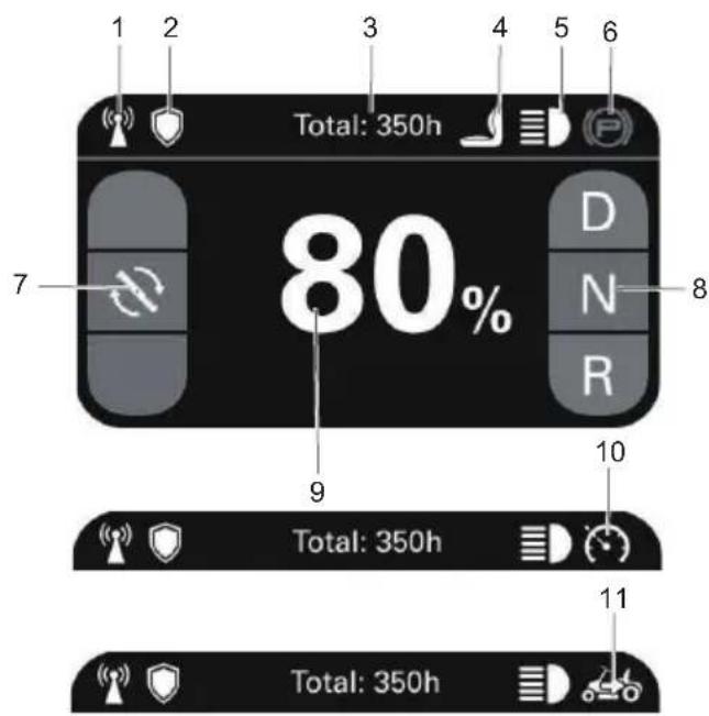
| #NameFunction | ||
| 1 4G GPS Signal | ||
| 2 GreenShield | ||
| #NameFunction | ||
| 3 Total : 350h | Vehicle working time | |
| 4 The seat switch is closed. | ||
| 5 LED Lights | ||
| 6 The parking brake is engaged. | ||
| 7 Blade speed | ||
| 8 | D/N/R | Driving direction: Drive (D), Neutral (N) and Reverse (R). |
| 9 80% Battery percentage | ||
| 10 Cruise control | ||
| 11 Reverse mowing mode is activated. | ||
6ERRORS
The CANBUS system will take action to protect the user and machine when it detects an issue. When it acts to turn off the machine or a component, it will indicate that an error has occurred, and that error will be shown on the digital display. All electrical errors have a letter code followed by a number. The first letter describes the system that caused the error according to this chart:
| NameMeaning | |
| T Driver Controller and motor | |
| PMU Power management unit (in the battery compartment) | |
| ML Left blade motor controller | |
| MR Right blade motor controller | |
| V Vehicle | |
6.1 ERROR CODE
| Error Code Description Solution | ||
| T11 Overvoltage | The voltage is too high. Restart the power supply. | |
| T12 Undervoltage | The voltage is too low. Charge the battery pack before use. | |
| T13 Controller self-test error If you encounter this issue, contact your distributor for a solution. | ||
| T14 Drive motor | stalled Check if the drive wheels are stuck and restart the power supply. | |
| T15 Motor encoder error Check that the Hall-effect connector of Drive controller is properly connected, and then restart the power supply. | ||
| T16 Controller driver circuit error If you encounter this issue, contact your distributor for a solution. | ||
| T17 Drive part of controller overtemp The controller temperature is too high. Wait for the controller to cool down, and then restart the power supply. | ||
| T18 Drive motor overheat The motor temperature is too high. Wait for the motor to cool down, and then restart the power supply. | ||
| T21 Temperature sensor of the drive motor abnormal | Check the wiring of the temperature sensor for abnormalities. | |
| T22 Drive part of controller hardware overcurrent | The load is too high. Restart the power supply. | |
| T23 Pre-charge error Restart the power supply. | ||
| T25 Drive software overcurrent The load is too high. Restart the power supply. | ||
| T26 Drive MOS error If you encounter this issue, contact your distributor for a solution. | ||
| T27 Motor phase loss Check that motor cables of the Drive controller are connected properly, and then restart the power supply. | ||
| T28 Drive controller overtemp The controller temperature is too high. Wait for the controller to cool down, and then restart the power supply. | ||
| V14 | Reverse mowing operation sequence incorrect | Please press the reverse mowing button before reverse mowing. |
| V15 | Vehicle self-test error | Before starting the vehicle, check that the brake is in the engaged position.Before starting the vehicle, place the cutter switch in the off position and check that the cutter switch is connected properly.Before starting the vehicle, place the FNR gearstick in the N position.Check that the connector underneath the seat is connected properly.Do not press the cruise control button when starting the vehicle.Do not press the accelerator pedal when starting the vehicle. |
| V16 | Operation sequence incorrect | Return the accelerator and blade switch to their initial positions. |
| V17 | SPI communication error | Restart the power supply. |
| V18 Battery compartment (PMU) failure Check that the accelerator cables are connected properly and restart the power supply. | ||
| V22 blade signal abnormal Check that the blade start switch is connected properly, and then return the switch to its initial position. | ||
| V21 PMU CAN communication error Communication with the battery compartment timed out. Restart the power supply. | ||
| V23 Operator presence switch abnormal Check that the connector under the seat is connected properly, and then restart the power supply. | ||
| ML3 Left blade software overcurrent Check the mowing load and restart the power supply. | ||
| ML4 Left blade stalled Check the mowing load and return the blade start switch to its initial position. | ||
| ML6 Left blade MOS error If you encounter this issue, contact your distributor for a solution. | ||
| ML7 Left blade motor phase loss Check that the blade controller and motor cables are connected properly, and then restart the power supply. | ||
| ML9 Left blade controller temperature abnormal The controller temperature is too high. Wait for the controller to cool down, and then restart the power supply | ||
| ML14 Left blade hardware overcurrent Check the mowing load and restart the power supply. | ||
| ML15 Left blade failed to start Check the mowing load and return the blade start switch to its initial position. | ||
| MR3 | Motor lowspeed protection Check the mowing load and restart the power supply. | |
| MR4 | Motor overspeed protection Check the mowing load and return the blade start switch to its initial position. | |
| MR6 | Motor Hall-sensor error If you encounter this issue, contact your distributor for a solution. | |
| MR7 | Controller phase loss Check that the blade controller and motor cables are connected properly, and then restart the power supply. | |
| MR9 | MOSFET open circuit error The controller temperature is too high. Wait for the controller to cool down, and then restart the power supply. | |
| MR14 | Controller undervoltage Check the mowing load and restart the power supply. | |
| MR15 | Controller overvoltage Check the mowing load and return the blade start switch to its initial position. | |
| PMU10 | Battery pack open circuit error The temperature of the battery compartment and battery is too low. Use the machine at a suitable temperature and restart the power supply. | |
| PMU11 | PMU major error The temperature of the battery compartment and battery is too high. Wait for the battery to cool down, and then restart the power supply. | |
| PMU12 | PMU secondary error A major error in the battery compartment prevented the drive and blade systems from starting. Restart the power supply and try again. | |
| PMU13 | No battery pack available Check that you are using the correct battery pack, and then restart the power supply. | |
| PMU | Insufficient battery packs available, functionality may be limited. Please insert more battery packs. | |
English
| Error Code Description Solution | ||
| NA Display communication error Please check the display's connecting parts and CAN network. | ||
7 MAINTENANCE
Check the mower blades daily. They are the key to power efficiency and well-groomed turf. Keep them sharp -- a dull blade will tear rather than cut the grass, leaving a brown ragged top on the grass within a few hours. A dull blade also requires more power. Replace any blade that is bent, cracked or broken.
WARNING
Never attempt to straighten a bent blade by heating, or weld a cracked or broken blade as the blade may break and cause serious injury. Replace worn or damaged blades.
WARNING
Never work with blades while key is in the ignition switch. Turn key to "OFF" position, remove the battery packs from the machine. Block up mower when you must work under it. Wear gloves when handling blades. Always check for blade damage if mower strikes a rock, branch or other foreign objects!
DANGER
Touch-up sharpening can be done with a file. Check the blades for balance following grinding. A commercial balancing tool is available through most hardware supply stores, or balancing can be done by placing the blade on an inverted line punch or 12.7mm (1/2") bolt. Blade should not lean or tilt. While spinning the blade slowly, it should not wobble. If blade is out of balance, true it up before reinstalling. Lay the blade on a flat surface and check for distortion. Replace any distorted blade.
WARNING
- The blade sail (curved part) must be pointing upward toward the inside of the deck to ensure proper cutting.
- When mounting blades, rotate them after installation to ensure blade tips do not touch each other or sides of the mower.
- Failure to correctly torque the bolt may result in the loss of the blade, which can cause serious injury.
- Mower blades are sharp and can cut. Wear gloves and use extra caution when servicing them.
7.1.1 REPLACE THE BLADE
See figure 17
- Stop the motor, remove the start key, and set the parking brake.
- Raise the height of the cutting deck to its highest position to allow access to blades.
i NOTE
If necessary, raise the mower by placing on a lift or using a jack and jack stands, or remove the cutting deck as described in the previous section to gain access to the blades.
WARNING
If raising the mower to access the blades, make sure the mower is properly secured and the parking brake is set before proceeding. Failure to properly secure the mower could cause it to fall, resulting in death or possible serious personal injury.
- Wedge a block of wood between the blade and mower deck to prevent the blade from turning.
- Loosen the blade nut by turning it counterclockwise (as viewed from bottom of mower) using a 16 mm wrench or socket (not provided).
English
EN
- Remove the blade nut, spacer, blade insulator, and blade.
- Thread the blade nut on the shaft and finger tighten.
- Torque the blade nut down clockwise using a torque wrench (not provided) to ensure the bolt is properly tightened. The recommended torque for the blade nut is 90 N.m\~100N.m (66\~74 ft.lbs).
WARNING
Ensure blade is properly seated and the blade nut is tightened to the torque specifications above. Failure to properly attach the blade could cause it to come loose and result in possible serious personal injury.
- Repeat with second blade, if needed.
i NOTE
Make certain all parts are replaced in the exact order in which they were removed.
7.2 REPLACE THE HEADLIGHT
See figure 18
Call customer service or visit our website online to order a new headlight.
- Park the mower on a level surface and set the parking brake.
- Stop the motor and remove the start key.
- Remove and set aside the hex head screw and flat washer holding the mower floor panel in place.
- Lift floor panel slightly to access the two hex head screws and flat washers securing the headlight in place. Remove screws and washers and set aside.
- Unplug the old headlight and discard.
- Plug in new headlight and reinstall washers and screws. Tighten securely.
- Lower floor panel and reinstall washer and screw to secure.
7.3 TIRES
It is important for level mowing that all tires have the correct amount of air pressure. The recommended pressure are:
i NOTE
Tire pressure should only be measured or adjusted when tires are cold.
Drive wheels 8 psi
Front caster wheels 24 psi
i NOTE
Inspect the tires daily. Replace immediately if damaged.
WARNING
Check the tire pressure carefully while inflating. Too much air in the tire could cause the tire to burst, causing serious personal injury.
7.4 LUBRICATION
See figure 19
Please add oil before operation.
| Oil type SAE85W-140 | |
| Oil capacity 180 ml |
Contact your Cramer dealer to replace the lubrication.
i NOTE
Replace the gearbox oil after you operate the machine for 50 hours for the first time, then replace the oil every 200 hours.
7.5 TORQUE VALUES
WARNING
Particular attention must be given to tightening the drive wheel lug nuts and blade spindle bolts. Failure to correctly torque these items may result in the loss of a wheel or blade, which can cause serious damage or personal injury.
Torque values are given below:
| Part Ft-lbs. Nm | ||
| Wheel (lug) nuts 89 120 | ||
| Blade spindle bolt 66 90 |
Lug nuts only -It is recommended that these be checked after the first 2 hours of operation, initially, every 100 hours and following removal for repair or replacement.
Your Cramer mower is powered by a battery pack which, when maintained properly, will provide years of useful life. For proper care, adhere to the following instructions:
• Always charge batteries after each use.
- Whenever a battery pack is fully discharged and turned off, it is best to recharge the battery as soon as possible. Over-discharge of the battery pack means the battery life will be shortened and the battery may become permanently damaged. There is no need to fully charge; it will be beneficial even if you only charge the battery pack for 5-10 minutes. It is best to recharge it within 24 hours.
- Keep grass, dirt and debris from collecting near battery terminals and in battery area.
- Charge batteries indoors in a well-ventilated and dry location away from sparks or flames. Never expose charger to rain, vapor or liquid.
- Charge only lithium batteries provided by Cramer.
- Do not touch uninsulated portion of charger (terminal pins) or of output connector.
- Do not use with defective cords and wires. Replace defective cords and wires immediately.
- For long-term storage, please make sure the storage temperature is -20°C - 45°C within one month, and 0°C - 35°C between two and twelve months.
- The working environment of the battery pack is -20°C - 55°C for discharge, and 0°C 55°C for charge.
7.7 BATTERY COMPARTMENT FILTER MAINTENANCE
Replace the battery compartment filter every 200 hours.
7.8 SERVICE
i IMPORTANT
Wait for all movement to stop before adjusting, cleaning or repairing. Repairs or maintenance requiring power should be performed by trained maintenance personnel only. Read and observe safety warnings in front of manual.
i IMPORTANT
Repairs or maintenance requiring power should be performed by trained maintenance personnel only.
- Park the mower on level ground. Make sure that steering control levers are in the neutral position, and that the PTO switch is in "OFF" position. Raise deck, rotate key to "OFF" position, remove key from switch and remove the battery packs from the battery compartment under the seat.
English
EN
- Any maintenance operation that requires the removal of safety covers must be performed by a trained service technician.
- Use a stick or similar instrument to clean under the mower, making sure that no part of the body -- especially arms and hands -- is under mower.
- Keep your machine clean and remove any deposits of trash and clippings.
- Keep battery compartment, deck and operator's station clean of accumulated trash, grass clippings, and other debris.
- Clean battery compartment, drive motor compartment, mower deck, seat, etc., of all dirt and debris. To clean, use only compressed air. DO NOT use water, solvents, hard cleaners or abrasives.
- Always wear adequate eye protection when servicing the batteries or when grinding mower blades and removing accumulated debris. Never attempt to make any adjustments or repairs to the mower's drive system, mower deck or any attachment while the traction drive system is running. Repairs or maintenance requiring power should be performed by trained maintenance personnel only.
- Never work under the machine or attachment unless it is safely supported with jack stands. Make certain machine is secure when it is raised and placed on the jack stands.
- The jack stands should not allow the machine to move when the traction drive system is running and the drive wheels are rotating. Use only certified jack stands. Use only appropriate jack stands, with a minimum weight rating of 2000 pounds (907.2 kg) to block the unit up. Use in pairs only. Follow the instructions supplied with the vehicle stands.
- Do not touch hot parts of machine.
- Keep nuts and bolts tight, especially the blade attachment bolts. Keep equipment in good working condition.
- Never tamper with safety devices. Check their proper operation regularly.
- Turn the key to the "OFF" position before unclogging the discharge chute.
- Never clear the discharge chute with the machine running. Turn the key to the "OFF" position and be sure the blades have stopped before cleaning. Use a stick to clear a plugged discharge area. Never use your hand!
- Stop unit and allow blades to stop before unclogging chute. Grass collection system components are subject to wear, damage and deterioration, which could expose moving parts or allow objects to be thrown. Frequently check components and replace with manufacturer's recommended parts, when necessary.
- Exercise caution when working under the deck as the mower blades are extremely sharp. Wear gloves and use extra caution when servicing them.
- Use only genuine Cramer Mower parts to ensure that original standards are maintained.
• Always remove batteries when transporting unit. Keep unit free of grass clippings, leaves and other debris. - Check brake operation frequently. Adjust and service as required.
- Maintain or replace safety and instruction labels, as necessary.
- Have your ride-on lawn mower serviced by a qualified repair person using only identical replacement parts. This will ensure that the safety of the ride-on lawn mower is maintained.
- Recharge only with the charger specified by the manufacturer. A charger that is suitable for one type of battery pack may create a risk of fire when used with another battery pack.
8 TRANSPORTATION AND STORAGE
8.1 TRANSPORTATION
WARNING
Use extra care when loading or unloading the machine into a trailer. Press the low speed drive button and carefully move the drive levers as needed to control the speed. Always back onto the trailer when loading. When loading or unloading the mower, do not exceed the maximum recommended operation angle of 15° . Failure to follow these instructions can result in loss of control and result in death, serious personal injury, or property damage.
WARNING
Use care when loading or unloading the mower onto a trailer. Ensure the cutting deck is raised to the highest position so that it is not caught on the ramp. The wheels on the mower can go off the ramp or trailer, causing the mower to pivot or tip over, and result in a crush hazard that can cause death or serious personal injury.
- Park the mower on a level surface.
- Raise the cutting deck to the highest position.
- Position and secure ramp to the trailer according to manufacturer's instructions.
i NOTE
We recommend you use one full width loading ramp that is at least 1 ft. wider than the mower to minimize the risk of the mower's wheels going off the side of the ramp.
- Slowly back the mower onto the ramp and into the trailer.
- Lower mower deck completely.
- Set the parking brake.
- Turn off mower and remove key.
- Secure the mower as needed using straps or cables to prevent movement during transport.
WARNING
To avoid accidental starting or movement that could result in serious personal injury, always remove the start key and set the parking brake when transporting the mower.
8.2 CLEAN AND STORAGE
8.2.1 CLEAN THE MACHINE
- Remove any build-up of grass and leaves on or around the motor cover (Do not use water from a high-pressure gun to flush the motor).
- Occasionally wipe the mower clean with a dry cloth.
- If debris builds up on the underside of the mower during use, stop the motor, turn off the machine, and scrape it clean using an appropriate tool.
8.2.2 CLEAN THE MOWER DECK
See figure 20
- Set the parking brake into the parking slots.
- Adjust the mower deck height to the lowest.
- Attach the supplied wash-port quick-coupler to garden hose.
- Attach garden hose with quick-coupler to wash port on the mower deck. The wash port is on the left side of the mower deck.
- Turn on the water.
- Pull the PTO switch to start the mower cutting blades and adjust the blade speed to the highest.
- Flush water under the deck for approximately one minute.
- Disengage the mower blades by pushing the PTO switch downward.
- Turn off the water and remove garden hose and quick-coupler from wash port.
- Remove quick-coupler from garden hose and store for future use.
- Turn off the mower completely.
8.2.3 STORE THE MACHINE
The following steps should be taken in order to prepare the machine for storage.
- Clean the machine as described in the previous section.
- Inspect the blade and replace it or sharpen it, if required (refer to the Maintenance section).
- Do not store the machine next to corrosive materials, such as fertilizer or rock salt.
- Keep the machine out of the reach of children.
- Do not cover the machine with a solid plastic sheet. Plastic coverings trap moisture around the machine, which causes rust and corrosion.
- Check thoroughly for any worn or damaged parts that need replacing and order them from your dealer.
- Please contact sevice center to thoroughly lubricate machine.
-
Fully charge and service the batteries.
-
Do not deflate tires.
- The machine should be stored in a well-ventilated, clean and dry place as the battery charger cannot be used in a wet environment.
- Always keep the batteries fully charged. It is especially important to prevent battery damage when the temperature is below 32°F (0°C).
- Attach the charger adapter to the charging port and the batteries per the Charging Adapter section in the Electrical System section.
- Plug the charger into a proper electrical outlet. Refer to Battery Charger, Battery Charging and Charging Recommendations portions of the Electrical System section for more details on using the charger and charging the batteries.
- To maximize battery life it is best to fully charge batteries shortly after each use.
8.2.4 PREPARE FOR USE AFTER STOAGE
The following steps should be taken before using the mower after it has been stored:
• Fully charge the batteries.
- Check tire pressure and inflate as needed.
- Briefly drive the mower and check all systems and components to ensure they are functioning correctly.
9 TROUBLESHOOTING
| PROBLEM POSS | IBLE CAUSE SOLUTION | |
| Vehicle won't move. | The battery compartment is not inserted into the battery pack or not Cramer designated battery pack. | To ensure the normal operation of the vehicle, at least 1 piece of Cramer designated battery pack products should be placed in the battery compartment. |
| Battery pack is not charged. Check the | battery pack power. | |
| No one is sitting on the seat or the operator presence switch is not closed. | Make sure the driver is sitting on the seat. | |
| The parking brake is engaged. Make sure you fully disengage the park brake, so the wheels can rotate freely. | ||
| The battery compartment is in dormant state. | Turn the key switch to OFF gear and wait for more than 5 seconds before restarting the machine. | |
| Sudden breakdown during driving | Battery is not charged. To ensure the normal operation of the whole vehicle, it is necessary to place at least 1 piece of Cramer designated battery pack products in the battery compartment and ensure that the battery pack has power. | |
| Rough and bumpy roads, resulting in disconnection of the operator presence switch. | Set the parking brake, and restart the machine and push the joystick. | |
| Gas pedal failure. Contact Cramer after-sales service staff.. | ||
| Drive controller failed. Contact Cramer after-sales service staff.. | ||
| The blade does not operate after pulling the PTO switch. | The battery compartment is not inserted in the battery pack specified by Cramer. | To ensure the normal operation of the whole vehicle, it is necessary to place at least 1 piece of Cramer designated battery pack products in the battery compartment and ensure that the battery pack has power. |
| The battery power is lower than 5%. Check the battery pack power, if the battery power is low, charge the battery. | ||
| The operator presence switch is not closed. | Ensure the driver is sitting on the seat. | |
| The blade switch (PTO) is not in the initial position before power on. | Press the PTO and pull it up again. | |
| Blade motor blocking or other functional protection. | Check that there are no weeds and other foreign objects at the connection between the blade and the motor to ensure smooth blade rotation. It is recommended to pull up the deck and start the blade before adjusting the deck to required gear. | |
| Walking controller is malfunctioning. Ensure that there is no other error shown on display. | ||
| The blade stops when mowing grass. | Blade controller is malfunctioning. Check the error code appearing on the display. | |
| Blade motor overload. Clean the inside of the deck, make sure there is no abnormal blade rotation, press the PTO, restart the machine and reduce the blade load, either by raising the height of the cutting deck or reducing the driving speed. | ||
| Battery pack temperature is too high. Do not use it immediately after charging is completed, otherwise it may trigger the battery pack temperature protection error. | ||
| The battery power is lower than 5%. The battery pack power is low, please charge the battery. | ||
| The blade is hit by a foreign object, causing a sudden stop. | Turn the key to OFF position and wait for more than 5 seconds before restarting the machine. | |
| Drive controller is malfunctioning. Check the error code appearing on the display. | ||
| The mower cuts the grass un-evenly, and the height difference is very large. | The blade is blunt. Polish the blade according to the manual. | |
| Blade is bent. Replace the bending blade, replace the blade in accordance with the instructions, and wear protective gear. | ||
| Deck is not flat. Flatten the deck according to the instructions to ensure that the left and right heights are equal. | ||
| The actual mowing height does not match the marked mowing height chosen. | Loose fixing bolts of deck. Adjust the fixing bolts of deck to ensure that it is firmly installed. Note: the deck needs to be re-leveled after adjusting the mounting bolts. | |
| The deck has been seriously worn or damaged. | Replace a new deck. | |
| Abnormal vehicle shredding | The lawn is too wet. Before cutting, please check the grass condition. If the grass is too wet, please wait for the wind to dry or sunshine, wait for the lawn dew to dissipate before cutting. | |
| The mower is set to cut too much grass at one time. | If the grass is too dense and high, please raise the deck and avoid cutting heavy grass as much as possible. | |
| Excessive machine vibration | Blades are loose. Polish the blade according to the method in the manual. | |
| Blades are bent. Replace the bending blade, pay attention to the correct replacement of the blade in accordance with the instructions, and wear protective gloves. | ||
| Uneven deck. Flatten the deck according to the instructions to ensure that the left and right heights are equal. | ||
| Loose deck. Lock the fixed bolts of the deck. | ||
| The mower is set to cut too much grass at one time. | If the grass is too dense and high, please raise the deck, try to avoid cutting heavy grass. | |
| Grass leaves or debris left on the ground after mowing. | The mower is set to cut too much grass at one time. | If the grass is too dense and high, please raise the deck, if the grass is higher than 15cm, please use two mowing cycles to achieve the mowing effect, try to avoid cutting heavy grass. |
| The grass is too wet. Please check the grass condition before mowing, if the grass is too wet, please wait for the wind to dry or sunshine, wait for the lawn dew to dissipate before mowing. | ||
| Driving speed is too fast. Lower the driving speed. | ||
| Blade cutting speed is too low. Increase the speed level of blade. | ||
| Short mowing duration | Mowing heavy grass may result in short mowing duration. | Raising the deck or decreasing the speed of blade can increase the mower's usage time on one charge. |
| Mower runaway | Different tire pressure | Check the rear tire pressure of the mower regularly according to the manual. |
| Vehicle won't start after washing. | Improper cleaning, such as water into the LED screen, battery compartment and other electronic components parts. | Please follow the instructions to clean the machine.If the vehicle is accidentally drenched, please put the vehicle in a dry place for 12h or blow dry before use.Contact Cramer after-sales service staff.. |
| The mower is blocked. | Weeds and garbage piled up on the deck. | Please follow the instructions to clean the machine each time after you use the machine. |
| PROBLEM POSSIBLE CAUSE SOLUTION | ||
| In park, the machine slides rapidly on the slope and skids. | Severe tire wear. Contact the after-sales personnel to replace the tires. | |
| The electromagnetic brake is damaged or terribly worn. | Contact the after-sales personnel to replace the electromagnetic brake. | |
| Electromagnetic brake is manually released. | Check the electromagnetic brake and reset it to the initial position. | |
10 TECHNICAL DATA
| Model No. 82LT107 | |
| Voltage 82 V | |
| Gross vehicle weight 106±3 kg | |
| Length 170 cm | |
| Height 117 cm | |
| Width (with discharge) 135 cm | |
| Width (without discharge) 107 cm | |
| Deck width 107 cm | |
| Forward speed 0-8 mph | |
| Reverse speed 0-3 mph | |
| Cutting height range | 3.81-11.4 cm |
| Cutting height adjustment level | 7 pcs |
| No load speed | 2400/3000/3200 RPM |
| Charging time | 4 h (with 8 A charger) |
| Motor power | 1.2 kW (blade motor) |
| 1.2 (drive motor) | |
| MAX slope handling | 15° |
| Number of blades (discharge/mulch) | 2 pcs |
| Measured sound pressure level | LpA = 84.77 dB(A), KpA = 3 dB(A) |
| Measured sound power level | LwA = 98.24 dB(A) |
| Guaranteed sound power level | LwA.d = 100 dB(A) |
| Vibration | Arms: ≤2.5 m/s2, K= 1.5 m/s2 |
| Body: ≤2.5 m/s2, K= 1.5 m/s2 |
11 LIMITED WARRANTY
11.1 WHAT IS COVERED BY THIS WARRANTY
Cramer makes the following warranty to the original purchaser("Owner") only - warranty is non-transferable:
A. Residential Use: Cramer product used for normal residential purposes* are warranted for five (5) years or 1,500 hours total usage (whichever comes first) from date of purchase on all materials and workmanship of chassis, deck and batteries. Consumables such as tires and blades are warranted for thirty (30) days from the date of purchase. If the Owner discovers within this warranty period a defect in materials or workmanship:
English
EN
- Owner must promptly notify Cramer or an authorized dealer in writing or via email, phone call, app or in person of the defect. In no event shall such notification be received by Cramer, or an authorized dealer, later than five (5) years from the date of purchase.
- Within a reasonable time after such notification, and verification of warrantable defect; Cramer will correct any defect in material or workmanship on the Cramer product by, at its option, repairing or replacing part(s) with either new or used replacement parts.
- Such repair, including parts and labor, shall be at the expense of Cramer to the original Owner only.
B. Commercial Use: Cramer product used for commercial and institutional use are warranted for five (5) years or 1,500 hours total usage (whichever comes first) from date of purchase on all materials and workmanship of chassis, deck, and batteries. Consumables (including but not limited to tires and blades) are warranted for thirty (30) days from the date of purchase. If the Owner discovers within this warranty period a defect in materials or workmanship:
- Owner must promptly notify Cramer or an authorized dealer in writing, via email, phone call, app or in person of the defect. In no event shall such notification be received by Cramer, or an authorized dealer, later than five (5) years from the date of purchase.
- Within a reasonable time after such notification and verification of warrantable defect Cramer will correct any defect in material or workmanship on the Cramer product by, at its option, repairing or replacing part(s) with either new or used replacement parts.
- Such repair, including parts and labor, shall be at the expense of Cramer to the original Owner (commercial) only.
i NOTE
Failure to properly maintain batteries and keep them fully charged will reduce battery life and will void the battery warranty. The provisions of this limited warranty shall not apply to failure due to:
- Abuse or neglect such as: water damage, loose wiring or rusted or corroded hardware.
- Lack of proper maintenance; damage caused by improper installation of the battery; neglect, breakage, exposure to extreme temperature conditions including but not limited to freezing temperatures, hot temperatures, proximity to heat sources including warmers or fire, exposure to water or other substances, wreckage, operation of the battery in an overcharged or uncharged condition.
- A battery charged by systems other than the original equipment type battery charger.
Footnote: *" Normal residential purposes", as used herein, means use of Product on same lot as your home. Use at more than one location is considered commercial use, after which the commercial use warranty would apply.
11.2 WHO MUST PERFORM THE WARRANTY SERVICE
All warranty service shall be performed by a Cramer authorized dealer or Cramer authorized service technician. Service calls and/or transportation expense of the product to and from the authorized dealer, for warranty work, will be paid by the owner of the product. For warranty service, contact an authorized dealer.
11.3 WHAT IS NOT COVERED BY THIS WARRANTY
Cramer does not warranty:
• Repairs made by unauthorized persons.
- Damage caused by use of the Cramer product for purposes other than those for which it was designed.
- Damages caused by disasters such as fire, flood, wind, and lightening.
- Damages caused by neglect, abuse, abnormal use, improper or unreasonable use, accident, negligence, or misuse such as water damage.
- Repairs or replacement resulting from the use of unauthorized parts, accessories, or attachments.
- Repairs or replacement as the result if any alterations or modifications, in the determination of Cramer, which adversely affects the operation, performance or durability of the equipment.
- Products, components, or parts not manufactured by Cramer.
- Products that have had their identification altered, including but not limited to serial numbers removed and/or made illegible.
- Depreciation or damage caused by normal wear, lack of reasonable and proper maintenance, failure to follow the product's owner's manual operating, maintenance and adjustment instructions or other operational instructions provided by Cramer.
- Normal maintenance parts and service including, but not limited to, lubricants, tune-up parts, blades, blade sharpening, bearings, brake or steering adjustments.
- Products with unapproved programming for that product including alterations to parameters, aftermarket programming or adjustments, or any unapproved modification to components, electronics, or software.
11.4 DISCLAIMER OF WARRANTY
The foregoing warranties are in lieu of all other warranties, expressed or implied, including but not limited to the implied warranties of merchantability and fitness for a particular purpose. However, if the Cramer Product is purchased as a consumer product, any implied warranty of merchantability or fitness for a particular purpose is limited to the duration of this limited warranty. Some states do not allow limitations on how long an implied warranty lasts, so the above limitation may not apply to you. This warranty gives you specific legal rights, and you may also have other rights which vary from state to state.
11.5 LIMITATION OF REMEDIES
In no case shall Cramer be liable for any special, incidental, or consequential damages based upon breach of warranty, breach of contract, negligence, strict liability in tort, or any other legal theory. Such damages include, but are not limited to:
- Loss of profits
- Loss of savings or revenue
- Loss of use of the Cramer Product or any associated equipment
- Cost of capital
- Cost of any substitute equipment, facilities, services or downtime
- The claims of third parties, including customers, and injury to property
11.6 TIME LIMIT
Unless State law determines otherwise:
Any action for breach of warranty must be commenced within five (5) years or sixty (60) months from the date of purchase in a residential and/or commercial application.
In the event the date of manufacture exceeds a reasonable timeframe preceding first customer purchase, Cramer warranty may be subject to additional limitations.
11.7 NO OTHER WARRANTIES
This agreement is understood to be the complete and exclusive agreement between the parties, superseding all prior agreements, oral or written, and all other communications between the parties relating to the subject matter of this agreement.
11.8 OWNER'S RESPONSIBILITY
You must maintain your Cramer Product following the maintenance procedures described in your owner's manual. Such routine maintenance, whether performed by a dealer or by you, is at your expense.
This machine, like any other powered equipment, is potentially dangerous unless properly operated. Any operator must be cautious and always keep safety in mind. Any operator, prior to using the Cramer Product, should thoroughly familiarize themself with the owner's manual regarding operation and safety of the machine, as well as all safety warnings on the machine itself.
11.9 ALLOCATION OF RISKS
This agreement allocates the risks of product failure between Cramer and the Owner. This allocation is recognized by both parties and is reflected in the price of the goods.
11.10 WARRANTY REGISTRATION
Unless State law determines otherwise:
- Owners must register the unit with Cramer within ten (10) days following date of purchase.
- Registration can be completed by filling out the Warranty Registration Form, which is provided in the operator manual.
- Registration can also be completed by using forms online at cramertools.com or by using the app and providing proof of purchase (receipt including date of purchase).
12 EC DECLARATION OF CONFORMITY
Name and address of the manufacturer:
Name: Greenworks Tools Europe GmbH
Address: Brunnenweg 17, 64331 Weiterstadt, Germany
Name and address of the person authorised to compile the technical file:
Name: Ralf Pankalla
Address: Brunnenweg 17, 64331 Weiterstadt, Germany
Herewith we declare that the product
Category: Lawn Tractor
Model: 82LT107
Serial number: See product rating label
Year of Construction: See product rating label
- is in conformity with the relevant provisions of the Machinery Directive 2006/42/EC.
- is in conformity with the provisions of the following other EC-Directives:
• 2014/30/EU
• 2011/65/EU & (EU)2015/863
Furthermore, we declare that the following (parts/clauses of) European harmonised standards have been used:
• EN 62841-1, EN ISO 5395-1, EN ISO 5395-3, EN ISO 14982, IEC 62321-3-1, IEC 62321-4, IEC 62321-5, IEC 62321-6, IEC 62321-7-1, IEC 62321-7-2, IEC 62321-8
Place, date: 11.11.2022 Signature: Ted Qu, Quality Director
Ted Qu
Deutsch
DE
11.1 WAS WIRD DURCH DIESE GARANTIE ABGEDECKT
3.4 RUEDAS ANTI-CALVAS
Véase la figura 2
5.3 DISPLAY DIGITALE
7 Maintenance....114
7.1 Maintenance de lame de tondeuse..... 114
7.2 Remplacement de phare.... 115
7.3 Pneus....115
7.4 Lubrification.... 116
7.5 Valeurs de couple.... 116
7.6 Maintenance de pack-batterie.... 116
7.7 Maintenance de filtre de compartiment
de batterie....117
7.8 Entretien.... 117
8 Transport et stockage...... 118
8.1 Transport.... 118
8.2 Nettoyage et stockage....118
9 Dépannage.... 121
11.9 ASSIGNATION DES RISQUES
12 DÉCLARATION DE CONFORMITÉ CE
11.2 WIE MOET DE GARANTIESERVICE UITVOEREN?
11.7 GEEN ANDERE GARANTIES
Svenska
8 TRANSPORT OCH FÖRVARING
8.1 FRAKT
▲ WARNING
Norsk
7.1 VEDLIKEHOLD AV KLIPPEBLAD
11.2 HVEM SKAL UTF∅RE GARANTISERVICEN
| #NavnFunktion | |
| 1 4G GPS-signal | |
| 2 GreenShield |
| Nr. | Pavadini-mas | Funkcija |
| 1 4G GPS signalas | ||
6 KLAIDOS
10 TECHNINIAI DUOMENYS
4.2 MAŠINAS LIETOŠANA
4.2.1 MAŠINAS IEDARBINĀŠANA
i PIEZIME
6 KLÜMES
9 PROBLÉMU NOVĚRŠANA
11.7 CITU GARANTIJU NAV


- DECLARATION OF CONFORMITY (UK)
- ENGLISH
- 1 DESCRIPTION......4
- 2 UNPACK THE MACHINE...... 4
- 3 INSTALLATION.... 5
- 4 OPERATING INSTRUCTIONS......6
- 5 ELECTRICAL SYSTEM.... 10
- 6 ERRORS....11
- 7 MAINTENANCE....14
- 8 TRANSPORTATION AND STORAGE.....17
- 9 TROUBLESHOOTING...... 20
- 10 TECHNICAL DATA....22
- 11 LIMITED WARRANTY....22
- 12 EC DECLARATION OF CONFORMITY...25
- 1 DESCRIPTION
- 1.1 OVERVIEW
- 1.2 CONTROL PANEL
- 2 UNPACK THE MACHINE
- WARNING
- I IMPORTANT
- 3 INSTALLATION
- 3.1 INSTALL THE SEAT
- SEE FIGURE 3
- 3.2 INSTALL THE STEERING WHEEL
- I NOTE
- 3.3 INSTALL THE MULCH COVER
- SEE FIGURE 6
- 3.4 ANTI-SCALP WHEELS
- SEE FIGURE 2
- 3.5 USE THE APP
- SEE FIGURE 7-8
- 4 OPERATING INSTRUCTIONS
- 4.1 BEFORE OPERATION
- 4.1.1 ADJUST THE SEAT
- SEE FIGURE 9
- 4.1.2 ADJUST THE DECK CUTTING HEIGHT
- SEE FIGURE 10
- CAUTION
- 4.1.3 INSTALL THE BATTERY PACK
- SEE FIGURE 11
- 4.1.5 SAFETY INTERLOCK SYSTEM
- SEE FIGURE 12
- 4.2.2 SET THE CRUISE CONTROL
- 4.2.3 RELEASE THE CRUISE CONTROL
- 4.2.6 STOP THE MACHINE
- 4.2.8 USE THE USB PORT
- 5 ELECTRICAL SYSTEM
- 5.1 ELECTRICAL SYSTEM SAFETY
- 5.2 ELECTRICAL SYSTEM INFORMATION
- 5.3 DIGITAL DISPLAY
- 6ERRORS
- 7 MAINTENANCE
- DANGER
- 7.1.1 REPLACE THE BLADE
- 7.2 REPLACE THE HEADLIGHT
- 7.3 TIRES
- 7.4 LUBRICATION
- 7.5 TORQUE VALUES
- 7.7 BATTERY COMPARTMENT FILTER MAINTENANCE
- 7.8 SERVICE
- 8 TRANSPORTATION AND STORAGE
- 8.1 TRANSPORTATION
- 8.2 CLEAN AND STORAGE
- 8.2.1 CLEAN THE MACHINE
- 8.2.2 CLEAN THE MOWER DECK
- SEE FIGURE 20
- 8.2.3 STORE THE MACHINE
- 8.2.4 PREPARE FOR USE AFTER STOAGE
- 11 LIMITED WARRANTY
- 11.1 WHAT IS COVERED BY THIS WARRANTY
- 11.2 WHO MUST PERFORM THE WARRANTY SERVICE
- 11.3 WHAT IS NOT COVERED BY THIS WARRANTY
- 11.4 DISCLAIMER OF WARRANTY
- 11.5 LIMITATION OF REMEDIES
- 11.6 TIME LIMIT
- 11.7 NO OTHER WARRANTIES
- 11.8 OWNER'S RESPONSIBILITY
- 11.9 ALLOCATION OF RISKS
- 11.10 WARRANTY REGISTRATION
- 12 EC DECLARATION OF CONFORMITY
- DEUTSCH
- DE
- 11.1 WAS WIRD DURCH DIESE GARANTIE ABGEDECKT
- 3.4 RUEDAS ANTI-CALVAS
- 5.3 DISPLAY DIGITALE
- 7 MAINTENANCE....114
- 8 TRANSPORT ET STOCKAGE...... 118
- 9 DÉPANNAGE.... 121
- 11.9 ASSIGNATION DES RISQUES
- 12 DÉCLARATION DE CONFORMITÉ CE
- 11.2 WIE MOET DE GARANTIESERVICE UITVOEREN
- 11.7 GEEN ANDERE GARANTIES
- SVENSKA
- 8 TRANSPORT OCH FÖRVARING
- 8.1 FRAKT
- ▲ WARNING
- NORSK
- 7.1 VEDLIKEHOLD AV KLIPPEBLAD
- 11.2 HVEM SKAL UTF∅RE GARANTISERVICEN
- 6 KLAIDOS
- 10 TECHNINIAI DUOMENYS
- 4.2 MAŠINAS LIETOŠANA
- 4.2.1 MAŠINAS IEDARBINĀŠANA
- I PIEZIME
- 6 KLÜMES
- 11.7 CITU GARANTIJU NAV
Brand : Cramer
Model : 82LT107
Category : Lawn mower