82ZT132 - Lawn mower Cramer - Free user manual and instructions
Find the device manual for free 82ZT132 Cramer in PDF.


User questions about 82ZT132 Cramer
0 question about this device. Answer the ones you know or ask your own.
Ask a new question about this device
Download the instructions for your Lawn mower in PDF format for free! Find your manual 82ZT132 - Cramer and take your electronic device back in hand. On this page are published all the documents necessary for the use of your device. 82ZT132 by Cramer.
USER MANUAL 82ZT132 Cramer
natural_image
Line drawing of a grassy utility vehicle with wheels, motors, and a handle (no text or symbols)Cramer information label for customer to connect phone to the vehicle via APP (including QR code, paring code and serial number)
English
EN
1 Description......4
1.1 Overview.... 4
1.2 Packing list.... 4
2 Installation.... 4
2.1 Install the roll over protection structure (ROPS)....4
2.2 Install the steering control lever.... 4
2.3 Install the seat.... 4
3 Know your machine...... 4
3.1 Electric take off (ETO) socket for connecting accessories....4
3.2 Control panel.... 4
3.3 Steering control levers....5
3.4 Safety start interlock system....5
3.5 ROPS (Roll Over Protective Structure)......5
3.6 Anti-scalp Wheels....6
3.7 Neutral bypass knob....6
3.8 Use the connectivity function....6
4 Operation.... 6
4.1 Before operation.... 6
4.2 Operate the machine.... 7
4.3 Slope operation....8
4.4 App operation tips.... 8
5 Operation suggestions......9
6 Electrical system.... 11
6.1 Electrical system safety.... 11
6.2 Electrical system information.... 11
6.3 Battery and charger....11
6.4 Digital display....12
7 Maintenance....13
7.1 Mower blade maintenance....13
7.2 Tires.... 13
7.3 Lubrication....14
7.4 Torque values....14
7.5 Seat belt maintenance.... 14
7.6 ROPS maintenance....14
7.7 Battery pack maintenance....14
7.8 Service.... 15
8 Cleaning and storage......15
8.1 Clean the machine.... 15
8.2 Store the machine.... 15
9 Troubleshooting......16
10 Technical data....17
11 Limited warranty.... 17
11.1 What is covered by this warranty.... 17
11.2 Who must perform the warranty service...... 18
11.3 What is not covered by this warranty.... 18
11.4 Disclaimer of warranty.... 18
11.5 Limitation of remedies....18
11.6 Time limit.... 18
11.7 No other warranties.... 18
11.8 Owner's responsibility.... 18
11.9 Allocation of risks.... 19
11.10 Warranty registration.... 19
12 EC Declaration of conformity...... 19
1 DESCRIPTION
1.1 OVERVIEW
See separate figure sheet 1-12
1 ROPS (Roll Over Protective Structure)
2 Steering control levers
3 Safety belt
4 Left control panel
5 Right control panel
6 Height adjustment lever
7 Deck
8 Discharge chute
9 ETO socket
10 Charging port
11 Key of battery pack protection
12 Anti-scalp wheels
13 Front wheel
14 Drive wheel
15 Attachment port
16 Digital display
17 Push button switch
18 High/Low for driving speed
19 ON/OFF for blade (PTO)
20 Power ON/OFF for accessory (ETO)
1.2 PACKING LIST
See figure 0
- Unassembled machine (1)
- Upper handle assembly (1)
- ROPS assembly (1)
- Seat assembly (1)
- Blade assembly (1)
2 INSTALLATION
2.1 INSTALL THE ROLL OVER PROTECTION STRUCTURE (ROPS)
See figure 3
- Insert the celvis pin into the hole.
- Insert the R-pin into the hole on the celvis pin.
21 High/Low for blade speed
22 Clevis pin
23 R-pin
24 Thumb screw
25 Neutral bypass knob
26 Upper control lever
28 Lower control lever
29 Seat adjustment lever
30 Cyclone float knob
31 Deck height adjustment pin
32 Quick charging port
33 Standard charging port
34 Port cover
35 Mulching blade
36 Mulching cover
37 Side mulcher plate
38 Blade motor
39 Cutting blade
40 Side discharge chute
41 Seat plug
42 Magnetic bar
- Discharge chute assembly (1)
- Charger (1)
- Owner's manual (2)
- Figure sheet (1)
- Discharge chute assembly (1)
- Charger (1)
- Owner's manual (2)
- Figure sheet (1)
2.2 INSTALL THE STEERING CONTROL LEVER
See figure 4
- Align the upper control handle with the lower control handle.
- Insert the screw together with the washer into the hole.
2.3 INSTALL THE SEAT
See figure 5
- Place the seat assembly over the mounting brackets and align holes as shown.
- Connect the seat plug (41) to the machine.
- Install the bolts, washers and nuts and tighten securely.
- Make sure it is securely seated.
3 KNOW YOUR MACHINE
3.1 ELECTRIC TAKE OFF (ETO) SOCKET FOR CONNECTING ACCESSORIES
See figure 1 (Point 9)
The machine can be used together with other attachments such as the blower.
3.2 CONTROL PANEL
3.2.1 LEFT CONTROL PANEL
See figure 2
| # | Name Function |
| 16 | Digital display |
| 17 | Push button switch (See figure sheet picture 2) |
3.2.2 RIGHT CONTROL PANEL
See figure 2
| # Name Function | ||
| 18 | High/Low for driving speed | Allows operators to select a comfortable driving speed. Pressing it to “High Speed”” position means that the maximum drive speed will be 16 KM/H. Pressing it to “Low Speed” position means that the maximum drive speed will be 9 KM/H. Press it to “Low Speed” position for inexperienced operators or when trimming around objects, buildings and other obstacles.i NOTEGet comfortable with mower before using “High Speed” setting. The maximum speed may be adjusted at any time, whether the mower is in motion or not. |
| 19 | ON/OFF for blade (PTO) | This switch engages the blade motors. Pull the switch up to engage and push switch down to disengage the motors. |
| 20 | Power ON/OFF for accessory (ETO) | The machine can be used togheter with other attachments and accessories. |
| 21 | High/Low for blade speed | The user can choose between two cutting modes. High blade speed mode and low blade speed mode. Selection is dependent on grass environment.i NOTEMowing time will be increased when mowing in low blade mode. |
i IMPORTANT
Never engage blade motors when the deck is under load. Motors or deck could be damaged.
3.3 STEERING CONTROL LEVERS
The two levers control the mower's speed, direction, stopping, neutral lock, and parking brake. Levers are used to steer, accelerate, decelerate, stop, and change direction. When the control levers are in the park brake position, the mower will not move.
3.4 SAFETY START INTERLOCK SYSTEM
The machine is equipped with a safety start interlock system consisting of the parking brake switches, seat switch, and PTO switch.
The mower's safety start interlock system is also designed to protect the operator and others from accidental injury due to unintentional traction drive system starting.
Check mower safety start interlock system daily, prior to operation. This system is an important mower safety feature. It should be repaired immediately if it malfunctions. The machine incorporates a separate seat switch which will stop the drive system and blade motors when the operator is unseated for any reason while the mower is operating. This is a safety feature designed to prevent runaway or accidental entanglement.
WARNING
The safety interlock system must not be disconnected or bypassed. Doing so could cause the machine to operate unexpectedly, resulting in personal injury.
To inspect the system:
- The operator must be on the seat when testing the seat switch.
- Press the push button switch with magnetic bar inserted.
- Pull the steering control levers to the neutral position.
- Pull the PTO switch ON to engage the motor.
- Slowly raise off of the seat. The deck blade system should stop.
- If the deck blade system fails to stop when the operator is off of the seat and if the cause cannot be determined, contact your Cramer dealer immediately.
3.5 ROPS (ROLL OVER PROTECTIVE STRUCTURE)
A ROPS may minimize the Risk of injury or death from rollover. The two-post ROPS can be pivoted down by removing the clevis pins after pulling out on the R-pins so that the machine can operate under low-hanging tree limbs or other obstructions. Do not wear the seat belt when the ROPS is in the lowered position. Use the ROPS in the “folded” position only when it is absolutely necessary.
WARNING
Do not operate the mower with the ROPS folded (lowered position) -- a standard operating mode. A folded ROPS does not provide rollover protection.
WARNING
Always wear your seat belt unless the ROPS is folded down. In this case, the seat belt should never be worn.
WARNING
To minimize chance of injury or death from rollover:
- Keep ROPS in the raised and locked position and use the seat belt.
- Lower the ROPS only when absolutely necessary.
- Drive slowly and carefully. Raise the ROPS as soon as clearance permits. Read and follow slope operation instructions and warnings.
- Always fasten seat belt during operation of the machine (mower equipped with ROPS in “raised/up” position).
- Inspect the area to be mowed for proper overhead clearance (tree limbs, guy wires, doorways, etc.) Do not contact any overhead object with the ROPS.
WARNING
Always pull from the Zero Turn hitch. Do not attach chains or ropes to the ROPS for pulling purposes, as the machine can tip backwards.
3.6 ANTI-SCALP WHEELS
See figure 2
Anti-scalp wheel kits are standard on Cramer units. These anti-scalp wheels are designed to minimize scalping when mowing on rough, uneven terrain. After setting the cutting height, adjust the anti-scalp wheels so they extend below the deck but do not contact the ground. They should always be at least 0.6 cm to 1.9 cm below the deck. With the unit sitting on a flat level surface, the wheel position can be adjusted up or down as needed from 1.9 cm to 4.4 cm below the blade surface. Move the wheels up or down - using the different axle mount holes in the wheel mount bracket (if applicable on model).
3.7 NEUTRAL BYPASS KNOB
See figure 7-8
- Locate the Neutral Bypass Knobs behind the frame at the rear of the mower.
- Remove the (4) thumb screws holding in the mesh cover.
- Remove the neutral bypass knob from its original location and install it to the motor. Operate one or both of the knobs on the motor, as needed.
- Rotate the neutral bypass knobs clockwise to release drive brakes; counterclockwise to engage.
- Install the neutral bypass knob(s) back to its/their original location after completing maintenance.
WARNING
Never drive mower with the neutral bypass knob working. Always install the neutral bypass knob to the original position before driving! Failure to re-install the knob could cause serious damage to your mower and void mower warranty!
WARNING
Never pull the neutral bypass lever outside when the machine is working on the slope!
3.8 USE THE CONNECTIVITY FUNCTION
The connectivity box software can provide the location and data of the machine.
i NOTE
If the connectivity box is damaged or removed, the machine will go into limp home mode in which the machine can only be driven in low speed without the blade working.
4 OPERATION
4.1 BEFORE OPERATION
4.1.1 ADJUST THE STEERING CONTROL LEVER
The steering control levers can be adjusted for operator comfort. By loosening the cap screws that attaches the upper control lever to the lower lever, the upper control lever can be pivoted to fit the operator's personal preference. The steering control levers should be adjusted so that they align with each other when in the neutral position.
4.1.2 ADJUST THE SEAT
See figure 6
WARNING
Make sure seat pan is securely bolted down prior to each use to prevent seat from moving/tilting in the event of mower tipping or rollover.
The seat can be adjusted forward and rearward by moving the latch under the seat. Move the latch to left and pull the seat where you have the best control of the machine and are the most comfortable and then tighten the safety belt.
i NOTE
You can adjust the suspended pressure of the seat by turning the cyclone float knob. Turn clockwise the preload will increase and counterclockwise for the preload to reduce.
4.1.3 ADJUST THE DECK CUTTING HEIGHT
See figure 9
Before using the mower, raise the deck height to the cutting position best suited for your lawn.
Deck height is adjustable from 2.5-14 cm. Deck should be raised while mowing is in progress to avoid stumps, rocks or other obstacle that can be damage mower deck.
-
Stop the mower and disengage blades.
-
Press the push button switch and set the parking brake.
- Fully depress the deck height adjustment pedal.
- Insert the pin once the desired deck height is available.
- Fully depress the deck height adjustment pedal again.
Seat belt must be fastened while operating a mower equipped with ROPS in the raised and secured position. Do not wear the seat belt when the ROPS is in the lowered position.
- With magnetic bar inserted, press the push button switch to activate the machine.
- Check for the appropriate speed mode by pressing drive speed control button to "low speed" position.
i NOTE
It is always recommended to start out in low mode/slow speed.
- Pull right and left drive control levers inward until stops are contacted.
- Pull up on deck PTO switch to start cutting blades for mowing.
i NOTE
Only engage blades when drive control levers are in the NEUTURAL position! NEVER engage blades when moving!
- Push drive control levers forward for forward motion and pull for reverse motion.
i NOTE
Electric brake will engage after drive control levers are returned to neutral.
4.2.2 DRIVE THE MACHINE
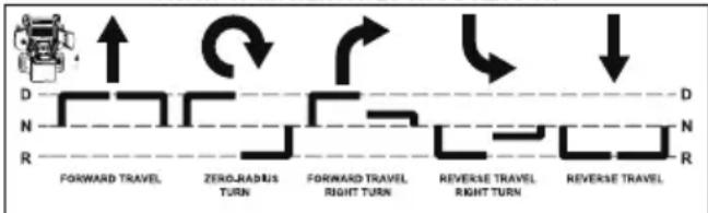
After starting the traction drive system, engage the steering control levers and steer as follows:
WARNING
Always be aware of what is behind the machine before backing up. Do not mow in reverse unless absolutely necessary. Always look down and behind before and while backing up.
▲ WARNING
Rapid movement of steering control levers is not recommended as damage to the electrical system components may occur.
- To go forward, push steering control levers forward an equal distance.
- To go in reverse, pull steering control levers rearward an equal distance.
- To turn left, move the right steering control lever farther forward from neutral than the left steering control lever.
- To turn right, move the left steering control lever farther forward from neutral than the right steering control lever.
- To execute a zero-radius turn, move one steering control lever forward and the other steering control lever back of neutral. This will allow the drive wheels to counter-rotate.
- To stop or decrease speed, move steering control levers to neutral. When going forward, pull back gently on steering control levers. When going in reverse, push forward gently on steering control levers.
- For an emergency stop, there are two methods that can be used:
- When traveling forward or in reverse, place the steering control levers in the park brake position immediately. When moving in the rearward direction, push forward gently on steering control levers and avoid sudden movement. Any sudden movement could cause the front of the mower to come off of the ground, resulting in possible loss of control, thereby causing serious injury or death.
- Press the push button switch and remove the magnetic bar. This will shut down the traction drive system and the deck drive system.
- To make a three-point turn to the right, move the left steering control lever farther forward from neutral than the right steering control lever and start the turn. Next, pull back on the steering control levers until they are past neutral and the machine starts to go rearward. Pull the right steering control lever farther rearward from neutral than the left steering control lever until the rear of the machine has pivoted around. Then, push the steering control levers forward until they are both past neutral and the machine starts to go forward. Push the left steering control lever farther forward from neutral than the right steering control lever and finish the turn.
- To increase speed, increase steering control lever's distance from neutral. The farther forward steering control levers are from neutral, the faster the machine will travel forward. The farther back steering control levers are from neutral, the faster the machine will go in reverse.
FRONT OF MOWER FACES THIS DIRECTION
flowchart
graph LR
    A["Start"] --> B["Forward Travel"]
    B --> C["Zero-Radius Turn"]
    C --> D["Forward Travel, Right Turn"]
    D --> E["Reverse Travel, Right Turn"]
    E --> F["Reverse Travel"]
    style A fill:#f9f,stroke:#333
    style F fill:#f9f,stroke:#333
N = NEUTRAL POSITION D = DRIVE POSITION R = REVERSE POSITION
Direction of arrows indicate direction of mower movement
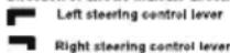
Left steering control lever
Right steering control lever
4.2.3 STOP THE MACHINE
DANGER
Never make sudden stops or reverse direction, especially when maneuvering on a slope. The steering is designed for sensitive response. Rapid movement of the steering control levers in either direction could result in a reaction of the machine that can cause serious injury.
- Return drive control levers to the Neutral position. Push drive control levers outward into park brake position.
- Push down on deck blades ON/OFF to turn off the blades.
- Press the push button switch.
CAUTION
It is recommended to remove the magnetic bar from the machine to prevent accident start of the machine.
4.3 SLOPE OPERATION
- Use extreme caution when operating on slopes.
- Do not remove or modify any wheels.
- Watch for holes, ruts, bumps, rocks or other hidden objects. Uneven terrain could overturn the machine. Tall grass can hide obstacles.
- Remove obstacles such as rocks, tree limbs, garbage etc.
- Keep all movement on slopes slow and gradual. Do not make sudden changes in speed or direction.
- Avoid starting and stopping on a slope. If tires lose traction, disengage the blades and proceed slowly straight down the slope.
- Mow a safe distance (minimum of 3 meters) away from drop-offs, retaining walls, drainage ditches, embankments, water, and other types of hazards to avoid a wheel dropping over the edge or the ground breaking away. This will reduce the risk of the machine suddenly rolling over, which could cause either serious injury or death.
- Use a walk-behind, push mower or hand-held trimmer on slopes and near drop-offs, retaining walls, drainage ditches, embankments and water.
- Do not mow on wet grass. Reduced traction could cause sliding and loss of steering control.
- Do not tow on slopes. The weight of the towed equipment may cause loss of traction and control.
- If the mower's tires lose traction when operating on slopes, disengage the deck drive, place the steering control levers in the park brake position, press the push button switch, remove the magnetic bar and get help.
- Never make sudden starts, stops, turns, or reverse direction, especially when maneuvering on slopes. The steering is designed for sensitive response. Rapid movement of the steering control levers in either direction could result in a reaction of the machine that can cause serious injury.
- Never stop suddenly while backing down slopes. This action may result in a reaction of the machine that can cause serious physical injury.
- The Cramer mower is capable of operating horizontally (traverse) on moderate slopes. When operating on slopes up to 20 degrees, be aware of any conditions that may cause the mower drive tires to lose traction, resulting in a possible loss of control of the machine. An operator should not operate on a slope until he is thoroughly familiar with the equipment.
Do not operate on slopes greater than 20 degrees.
Refer to Slope Guide, when determining the degree of slope to be mowed. It is strongly recommended that the operator drive the machine off of the slope, using extreme caution, if any sign of loss of traction is detected. Wait until the condition that caused the problem is resolved before attempting to operate on the slope again. Terrain conditions can affect traction, resulting in possible loss of control of the machine. Some of the conditions to be aware of are:
- Wet terrain
- Depressions in the ground (e.g., holes, ruts, washouts)
- Mounds of dirt
- Certain types of soil (e.g., sand, loose dirt, gravel, clay)
- Grass type, density, and height
- Extremely dry conditions
- Tire pressure
The attachments mounted to the mower will also affect the way it handles on a slope. Be aware that each attachment's characteristics vary.
These are just a few examples of situations where caution must be used when operating on a slope. There are many other possibilities too numerous to mention. Remember to always exercise extreme caution while operating on any slope.
- The ROPS may minimize risk of injury or death from rollover. Seat belt must be fastened while operating a mower equipped with ROPS in the raised and secured position. Both retaining pins and hair pins must be installed. Failure to use seat belt with ROPS will result in serious injury in the event of a rollover.
Find the serial number, pairing code and QR code in the vehicle matching label.
2. REGISTRATION AND LOGIN
See separate figure sheet 14
Step 1. Fill in the registration information (with * is required), and then click the "Create" button.
Step 2. Confirm User Rights. Give information usage consent.
Step 3. Confirm End User License Agreement. Click "Create account".
Step 4. Activate the account email, click "Continue". Open the email and click the activation link in it, and then continue to log in.
Step 5. Log in.
3. ADD A DEVICE
See separate figure sheet 15
Step 1. Click "Pair your mower" to add a device of Cramer machine.
Step 2. Find category of vehicle according to your device type, then click button “Pair” (Vehicle).
Step 3. Select your pairing method - "Scan QR code" or type in "Serial number and pairing code".
Step 4. When you select option "Serial number and paring code", just manually input serial number + paring code.
Step 5. Click "Finish" to end the procedure or click "Set up protective measurements" to continue.
4. GPS FUNCTION
(1) Upload data
See separate figure sheet 16
Connect your mobile phone to the APP, and you can check fault, speed, and battery power of the machine through the APP.
(2) GPS
See separate figure sheet 17
The machine is equipped with GPS function, you can connect your mobile phone to the machine by the APP. It is convenient to locate your machine and achieve anti-theft effect.
This icon shows the position where the vehicle was last connected on map. When click vehicle icon, it will show the device's name, latest latitude and longitude. You can click the copy icon to copy the value of latitude and longitude.
WARNING
The 4G & GPS connectivity device may lose the GPS satellite signal or cellular connection at any time. Due to heavy tree canopies, large buildings, poor weather conditions, electrical interference, dead zones, or other obstacles.
5 OPERATION SUGGESTIONS
DANGER
Prior to operation, the operator should be thoroughly familiar with the proper use and operation of the equipment, should read the manual completely and thoroughly, and should have attempted slow moving maneuvers to become familiar with the operation of the equipment before attempting normalspeed operation. An inexperienced operator should not mow on slopes or on uneven terrain.
WARNING
If you lose steering control while operating the machine, place the steering control levers in the park brake position immediately, press the push button switch and remove the magnetic bar. Inspect the machine and consult your Cramer dealer to resolve the problem before continuing to operate.
WARNING
The unit's steering control levers are very responsive. For smooth operation, move levers slowly, avoiding sudden movements. Skill and ease of operation come with practice and experience. The machine can spin very rapidly. Use caution when making turns and slow down before making sharp turns.
Inexperienced operators may have a tendency to oversteer and lose control. Slow-moving practice maneuvers are recommended to become familiar with these characteristics before attempting normal-speed operation.
WARNING
Sharp depressions or raised obstacles (such as gutters or curbs) should not be directly approached at high speed in an attempt to "jump" them as the operator could be thrown from the equipment. Approach at a slow speed and angle one drive wheel at the obstruction. Continue at an angle until the wheel clears and then pivot the opposite wheel around.
When turning on soft or wet turf, keep both wheels rolling either forward or backward. Pivoting on one stopped wheel can damage turf. Keep blades sharp. Many problems with incorrect cutting patterns are due to dull blades or blades which have been sharpened incorrectly. Blade sharpness should be checked daily.
▲ DANGER
Never service the machine while magnetic bar is inserted. Always pull out the magnetic bar when you are going to work with the machine. Always place deck blade switch in the disengaged position, place steering control levers in the park brake position and remove the magnetic bar from switch. Block up mower when you must work under it. Wear gloves when handling blades. Always check for blade damage if mower strikes a rock, branch, or another foreign object during mowing.
- Direct grass discharge to right, away from unmowed area. Select a mowing pattern that directs grass discharge towards the outside the mowing area. Generally, this means using a pattern utilizing left turns because side discharge is to the right. In any case, avoid throwing grass discharge onto unmowed area because grass is then mowed “twice.” Mowing twice puts an unnecessary load on the unit and reduces mowing efficiency.
- When mowing a lawn for the first time, cut grass slightly longer than normal to avoid scalping uneven terrain. When possible, it is best to use the cutting height that was used in the past. When cutting grass taller than six inches, you may want to mow the lawn twice to achieve a better quality of cut.
- During normal mowing, cut only about 1/3 of the grass. Cutting more than that is not recommended unless grass is sparse or it is the end of the mowing season.
• Alternate mowing pattern between cuts to keep the grass growing straight and better dispersion of the clippings. - Remember, grass grows at different rates at different time of the year. Mow more often in the early spring to maintain the same cutting height. As the growth rate slows in mid summer, mow less frequently. If you cannot mow at a regular interval, mow at a high cutting height at first, then mow again two days later at a lower cutting height.
- Raise the cutting height of the mower if the cutting width of the mower is wider than the previous mower. This ensures that uneven turf is not cut too short.
- Raise the cutting height of the mower if the grass if slightly taller than normal or if it contains a high degree of moisture. Then mow it again with the cutting height set lower.
- This mulching system permits easy breakdown of the grass clippings and returns grass clippings back to the soil. For the best mulching results, you never let your grass grow more than 1/3 longer than your desired height. When your grass reaches that height, you cut the top 1/3 away.
- If the machine's forward motion must be stopped while mowing, a clump of grass clippings may drop onto your lawn. To avoid this, move onto a previously cut area with the blades engaged.
- Charge the battery immediately.
| Model No. Battery capacity | capacity Action Battery capacity Action | ||
| 82ZT132 3% - 6% | The maximum drive speed will be 9 km/h and the unit will operate in lower blade speed mode. | <3% The working blade will stop automatically. The unit should immediately be returned to the battery charging area and the unit connected to the battery charger. |
- Allow motors 30 minutes to cool down. If drive motor exceeds programmed temperature, the motor speed will decrease. If temperature continues to increase, drive will shut down at a higher programmed temperature.
6 ELECTRICAL SYSTEM
6.1 ELECTRICAL SYSTEM SAFETY
- Remove the magnetic bar, disconnect battery cables by pulling inward on RED battery quick disconnect handle in battery box compartment and read owner's manual before adjusting or repairing unit.
- Always remove the magnetic bar and disconnect battery cables by pulling inward on RED battery quick disconnect handle in battery box compartment before working on this unit.
- Always disconnect battery cables by pulling inward on RED battery quick disconnect handle in battery box compartment when transporting unit.
- Keep unit free of grass clippings, leaves and other debris. DO NOT spray water to clean unit. Use only compressed air. Wear adequate eye and hearing protection when cleaning the unit.
• Always wear safety glasses and protective gear near battery. Use insulated tools. - Clean battery compartment, drive motor compartment, mower deck, seat, etc., of all dirt and debris. Do not use solvents, hard cleaners or abrasives.
- When the power switch activated, mower blade can engage when deck blade ON/OFF switch is engaged, even if drive motor is not turning. Keep area clear of bystanders when engaging deck blade ON/OFF switch.
- All maintenance and storage areas should be properly ventilated in accordance with applicable fire codes and ordinances to avoid fire hazards. Proper ventilation is required to remove hydrogen gas from the area during battery charging.
- Never allow flames, sparks or smoking near batteries.
- Keep batteries out of reach of children.
- Always keep protective shields, covers and guards in place and securely fastened. If they become damaged, repair or replace immediately. Never modify or remove safety devices.
6.2 ELECTRICAL SYSTEM INFORMATION
The Cramer mower is powered by an 82-volt electrical system. It consists of the following components:
- Blade controller (3) (Depending on model)
- Blade Motor (3) (Depending on model)
- Drive controller (2)
- Accelerator - right (1)
- Accelerator - left (1)
- Digital display (1)
- Motor drive assembly (2)
- Battery pack (1)
6.3 BATTERY AND CHARGER
WARNING
Maintenance for the various electrical components found on the Cramer Mower should only be performed by a Cramer Mower trained technician.
WARNING
When battery voltage becomes low, the mower blades will stop, although the drive motors will continue to run, enabling driver to continue to drive unit. When the batteries discharge to this point, they require recharging. The unit should immediately be returned to the battery charging area and the unit connected to the battery charger.
WARNING
Do not attempt to cross roads or railways with low battery levels.
6.3.1 BATTERY CHARGING PORT
See figure 10
The battery charging port is located on the right (with operator seated) housing of the machine. Open the port cover to charge. Both quick charging port and standard charging port are available.
6.3.2 CHARGING RECOMMENDATIONS
WARNING
Do not smoke while servicing the batteries.
WARNING
Always wear safety glasses and protective clothing near battery. Use insulated tools.
CAUTION
Charging recommendations
- Battery packs do not develop a memory and need not be fully discharged before recharging.
- Batteries left uncharged will slowly discharge. Before initial use each spring season, be sure batteries have a full charge before mowing.
- If charger is not left plugged in, the batteries should be fully charged every 30 days to maintain battery life. Never allow charger to charge more than 15 hours.
- When charging, be sure charger cooling fan inlet and outlet are not blocked.
6.3.3 CHARGE THE BATTERY
WARNING
More details of charger are referred to in the charger manual. Read and understand all its safety warnings and instructions. Failure to follow them may result in electrical shock, fire and/or serious injury.
- Press the push button switch.
- Remove the magnetic bar and make sure the machine comes to a complete stop.
- Remove the dust cap from the battery charging port on the mower.
- Plug the charger into the port.
- Plug other end of charger into household GFCI protected outlet.
▲ WARNING
Always turn charger "OFF" before disconnecting charger from mower. Disconnect charger cord from wall outlet.
▲ WARNING
Cover the battery charging port with the dust cap before operation.
6.4 DIGITAL DISPLAY
The function of the digital display, located on the control panel, is to provide electrical system information to the operator. It gives detailed information in the form of pattern, codes and number.
6.4.1 DIGITAL DISPLAY (FOR 82ZT132 SERIES)

text_image
1 2 3 4 5 6 7 8 9 10 STARTING STEUS GO ECO CUT 100% 20% 75% 50% 25% 10% A 2.6 B 0.7 MIS 1.8 L 9.1 M 7.2 R 8.3 11 TOTAL HOURS: 3 0 1 2 OVERALL STATUS CONTROLLER FAULT CUT HOURS: 8 5 6 7 12 13 14| # Name Function | ||
| 1 Low drive speed | ||
| 2 High drive speed | ||
| 3 Seat switch | ||
| 4 Left control lever | ||
| 5 Right control lever | ||
| 6 PTO switch | ||
| 7 The whole machine is OK | ||
| 8 Need to restart | ||
| 9 Low blades speed | ||
| 10 Blade working | ||
| 11 Batter remaining capacity | ||
| 12 Total hours Total working hours | ||
| 13 Overall status | Overall status | |
| 14 Cutting hours | Cutting hours | |
| 15 | L | Left blade motor fault code |
| A | Master controller fault code | |
| BMS | Battery fault code | |
| R | Right blade motor fault code | |
| B | Slave controller fault code | |
| M | Middle blade motor fault code | |
7 MAINTENANCE
Regular maintenance is the best prevention for costly downtime or expensive, premature repair. The following pages contain suggested maintenance information and schedules which the operator should follow on a routine basis. Remain alert for unusual noises, as they could be signaling a problem. Visually inspect the machine for any abnormal wear or damage.
Check the mower blades daily. They are the key to power efficiency and well-groomed turf. Keep them sharp -- a dull blade will tear rather than cut the grass, leaving a brown ragged top on the grass within a few hours. A dull blade also requires more power. Replace any blade that is bent, cracked or broken.
WARNING
Never attempt to straighten a bent blade by heating, or weld a cracked or broken blade as the blade may break and cause serious injury. Replace worn or damaged blades.
WARNING
Never work with blades while magnetic bar is in the ignition switch. Remove magnetic bar from switch and disconnect battery cables by pulling inward on RED battery quick disconnect handle in battery box compartment. Block up mower when you must work under it. Wear gloves when handling blades. Always check for blade damage if mower strikes a rock, branch or other foreign objects!
DANGER
The blade adapter will come off when the blade cap screw is removed. Touch-up sharpening can be done with a file. Check the blades for balance following grinding. A commercial balancing tool is available through most hardware supply stores, or balancing can be done by placing the blade on an inverted line punch or 12.7mm bolt. Blade should not lean or tilt. While spinning the blade slowly, it should not wobble. If blade is out of balance, true it up before reinstalling. Lay the blade on a flat surface and check for distortion. Replace any distorted blade.
WARNING
- The blade sail (curved part) must be pointing upward toward the inside of the deck to ensure proper cutting.
- When mounting blades, rotate them after installation to ensure blade tips do not touch each other or sides of the mower.
- Failure to correctly torque the bolt may result in the loss of the blade, which can cause serious injury.
- Mower blades are sharp and can cut. Wear gloves and use extra caution when servicing them.
7.1.1 REMOVE THE BLADE
See figure 11-12
You can cut the grass in two different ways: Side discharge blade and mulching blade. With the mulching blade, you can cut the grass more intensively.
- Remove the magnetic bar and disconnect battery cables by pulling inward on RED battery quick disconnect handle in battery box compartment.
- Lift the front of the mower and block and secure the machine to allow service man to change the blade under the mower.
- While wearing leather padded gloves, grasp the blade closely with one hand in order to prevent the blade from turning and use a 24mm wrench with your other hand to loosen the bolt fixing its blade in place.
- Turn the bolt COUNTERCLOCKWISE to loosen and CLOCKWISE to tighten.
- Remove the bolt, washer and the blade.
i NOTE
If you use the mulching blade, it is necessary for you to install the two mulcher covers, and the side mulcher plate. Otherwise, only install the side discharge chute.
7.1.2 INSTALL THE BLADE
- Place the blade with the cutting blade toward the ground.
- Install the bolt.
- Turn the blade bolt CLOCKWISE with a socket or wrench to secure the blade.
- Thread the blade nut on the shaft and finger tighten.
- Torque the blade nut down clockwise using a torquewrench (not provided) to ensure the bolt is properlytightened. The recommended torque for the blade nut is 155-160N.m.
7.2 TIRES
It is important for level mowing that all tires have the correct amount of air pressure. The recommended pressure are:
i NOTE
Tire pressure should only be measured or adjusted when tires are cold.
| Drive wheels 20 psi | |
| Front caster wheels 28 psi |
i NOTE
Inspect the tires daily. Replace immediately if damaged.
WARNING
Check the tire pressure carefully while inflating. Too much air in the tire could cause the tire to burst, causing serious personal injury.
7.3 LUBRICATION
i NOTE
Replace the gearbox oil after you operate the machine for 50 hours for the first time, then replace the oil every 500 hours.
| Brand Gear-box | Moto type | Gearbox ratio | Oil quantity | Oil brand |
| 82ZT132 SP600 AC | 32 0.6L | GL-5 | 85W-140 |
7.4 TORQUE VALUES
WARNING
Particular attention must be given to tightening the drive wheel lug nuts and blade spindle bolts. Failure to correctly torque these items may result in the loss of a wheel or blade, which can cause serious damage or personal injury.
Torque values are given below:
| Part | Ft-lbs. Nm | |
| Wheel (lug) nuts 83 | -118 112-132 | |
| Blade spindle bolt 1 | 14-118 155-160 |
Lug nuts only -It is recommended that these be checked after the first 2 hours of operation, initially, every 100 hours and following removal for repair or replacement.
7.5 SEAT BELT MAINTENANCE
Inspect the seat belt system (all seat, seat belt parts, seat pan and seat pan latch) daily prior to mowing for signs of any damage. These parts should be replaced if any parts indicate signs of:
• cuts
- fraying
• extreme or unusual wear
• significant discoloration due to UV exposure
- dirt or stiffness
• abrasion to the seat belt webbing
• damage to the buckle, latch plate or hardware
- any other problem
If the seat belt is to be cleaned, use soap and water. Do not use carbon tetrachloride, naphtha, etc., as these will weaken the webbing. For the same reason, do not bleach or dye the webbing. Replace seat belt if worn or damaged.
7.6 ROPS MAINTENANCE
ROPS Inspection
i NOTE
Inspect the ROPS after the first 20 hours of operation.
- Check the torque of the ROPS mounting bolts. Tighten the bolts to the correct torques (M12, 95N.m) if necessary.
- Inspect the operator's seat and the mounting parts for the seat belt. Tighten the bolts to the correct torque as shown below, if necessary, and replace parts that show wear or damage.
- Inspect the seat latch to make sure it is secured and functioning properly. Adjust or repair, as necessary.
Possible damage to the ROPS
If the unit has rolled over or the ROPS has been in some other type of accident (such as hitting an overhead object during transport), the ROPS must be replaced to retain the best protection. Following an accident, check the ROPS, the operator's seat, the seat belt, seat belt mountings and seat latch for possible damage. Before operating the machine, replace all damaged parts.
i NOTE
The ROPS structure's protective capability may be impaired by structural damage, overturn or alteration. Do not remove or alter any of the ROPS parts. Do not attempt to weld or straighten ROPS. Failure to adhere to these instructions could result in severe injury or death.
Your Cramer mower is powered by a battery pack which, when maintained properly, will provide years of useful life. For proper care, adhere to the following instructions:
• Always charge batteries after each use.
- Whenever a battery pack is fully discharged and turned off, it is best to recharge the battery as soon as possible. Over-discharge of the battery pack means the battery life will be shortened and the battery may become permanently damaged. There is no need to fully charge; it will be beneficial even if you only charge the battery pack for 5-10 minutes. It is best to recharge it within 24 hours.
- Check that battery cables are securely tightened to batteries each time you service the battery.
- Keep grass, dirt and debris from collecting near battery terminals and in battery area.
- Charge batteries indoors in a well-ventilated and dry location away from sparks or flames. Never expose charger to rain, vapor or liquid.
- Charge only lithium batteries provided by Cramer.
- Do not touch uninsulated portion of charger (terminal pins) or of output connector.
- Do not use with defective cords and wires. Replace defective cords and wires immediately.
- For long-term storage, please make sure the storage temperature is -20^ - 45^ within one month, and 0^ - 35^ between two and twelve months.
- The working environment of the battery pack is -20^ -55^ for discharge, and 0^ 55^ for charge.
7.8 SERVICE
i IMPORTANT
Wait for all movement to stop before adjusting, cleaning or repairing. Repairs or maintenance requiring power should be performed by trained maintenance personnel only. Read and observe safety warnings in front of manual.
i IMPORTANT
Repairs or maintenance requiring power should be performed by trained maintenance personnel only.
- Park the mower on level ground. Make sure that steering control levers are in the neutral position, and that the deck blade switch is in "OFF" position. Raise deck, remove the magnetic bar and disconnect battery cables by pulling inward on RED battery quick disconnect handle in battery box compartment.
- Any maintenance operation that requires the removal of safety covers must be performed by a trained service technician.
- Before working on or under the deck, make certain the magnetic bar is removed and deck blade switch cannot be accidentally started and disconnect battery cables by pulling inward on RED battery quick disconnect handle in battery box compartment.
- Use a stick or similar instrument to clean under the mower, making sure that no part of the body -- especially arms and hands -- is under mower.
- Keep your machine clean and remove any deposits of trash and clippings.
- Keep battery compartment, deck and operator's station clean of accumulated trash, grass clippings, and other debris.
- Clean battery compartment, drive motor compartment, mower deck, seat, etc., of all dirt and debris. To clean, use only compressed air. DO NOT use water, solvents, hard cleaners or abrasives.
- Always wear adequate eye protection when servicing the batteries or when grinding mower blades and removing accumulated debris. Never attempt to make any adjustments or repairs to the mower's drive system, mower deck or any attachment while the traction drive system is running. Repairs or maintenance requiring power should be performed by trained maintenance personnel only.
- Never work under the machine or attachment unless it is safely supported with jack stands. Make certain machine is secure when it is raised and placed on the jack stands.
- The jack stands should not allow the machine to move when the traction drive system is running and the drive wheels are rotating. Use only certified jack stands. Use
only appropriate jack stands, with a minimum weight rating of 2000 pounds (907.2 kg) to block the unit up. Use in pairs only. Follow the instructions supplied with the vehicle stands.
- Do not touch hot parts of machine.
- Keep nuts and bolts tight, especially the blade attachment bolts. Keep equipment in good working condition.
- Never tamper with safety devices. Check their proper operation regularly.
- Remove the magnetic bar before unclogging the discharge chute.
- Never clear the discharge chute with the machine running. Remove the magnetic bar and be sure the blades have stopped before cleaning. Use a stick to clear a plugged discharge area. Never use your hand!
- Stop unit and allow blades to stop before unclogging chute. Grass collection system components are subject to wear, damage and deterioration, which could expose moving parts or allow objects to be thrown. Frequently check components and replace with manufacturer's recommended parts, when necessary.
- Exercise caution when working under the deck as the mower blades are extremely sharp. Wear gloves and use extra caution when servicing them.
- Use only genuine Cramer Mower parts to ensure that original standards are maintained.
- Always disconnect batteries when transporting unit. Keep unit free of grass clippings, leaves and other debris.
8 CLEANING AND STORAGE
8.1 CLEAN THE MACHINE
- Remove any build-up of grass and leaves on or around the motor cover (Do not use water from a high-pressure gun to flush the motor).
• Occasionally wipe the mower clean with a dry cloth. - If debris builds up on the underside of the mower during use, stop the motor, turn off the machine, and scrape it clean using an appropriate tool.
8.2 STORE THE MACHINE
The following steps should be taken in order to prepare the machine for storage.
- Clean the machine as described in the previous section.
- Inspect the blade and replace it or sharpen it, if required (refer to the Maintenance section).
- Do not store the machine next to corrosive materials, such as fertilizer or rock salt.
- Keep the machine out of the reach of children.
- Do not cover the machine with a solid plastic sheet. Plastic coverings trap moisture around the machine, which causes rust and corrosion.
-
Check thoroughly for any worn or damaged parts that need replacing and order them from your dealer.
-
Please contact sevice center to thoroughly lubricate machine.
- Fully charge and service the batteries.
- Do not deflate tires.
- The machine should be stored in a well-ventilated, clean and dry place as the battery charger cannot be used in a wet environment.
• Always keep the batteries fully charged. It is especially important to prevent battery damage when the temperature is below 32^ F ( 0^ C).
- Attach the charger adapter to the charging port and the batteries per the Charging Adapter section in the Electrical System section.
- Plug the charger into a proper electrical outlet. Refer to Battery Charger, Battery Charging and Charging Recommendations portions of the Electrical System section for more details on using the charger and charging the batteries.
- To maximize battery life it is best to fully charge batteries shortly after each use.
9 TROUBLESHOOTING
| PROBLEM POSSIBLE CAUSE SOLUTION | ||
| If error pattern are showing on the digital display. | Numerous. Refer to Digital display in the | section of this manual. |
| Contact your Cramer dealer. | ||
| There is abnormal vibration. | The cutting blade(s) is/ are bent or unbalanced. | Install new cutting blade(s). |
| A blade mounting bolt is loose. Tighten the | blade mounting bolt. | |
| Numerous. Contact your Cramer dealer. | ||
| Uneven cutting height. | The blade(s) are not sharp. Sharpen the blades. | |
| A cutting blade(s) is/are bent. Install new cutting blade(s). | ||
| The deck is not level. Level the deck per the Deck leveling and height adjustment section of the parts manual. | ||
| An anti-scalp wheel is not set correctly. Adjust the height of the anti-scalp wheel. | ||
| The underside of the deck is dirty. Clean the underside of the deck. | ||
| Tires improperly inflated. Adjust air pressure and ensure even pressure between tines. | ||
| A blade spindle is bent. Contact your Cramer dealer | ||
| Loss of deck operation. | If deck control does not provide image to the Digital Display and the deck fails to operate with fully charged batteries. | Contact your Cramer dealer. |
| Mower will not start. | The magnetic bar is removed. (See figure 2) | Check that the magnetic bar is inserted. |
| Battery is not charged. Check all battery connections in back battery compartment. Make sure batteries are charged | ||
| Circuit breakers are tripped. Check to see that all circuit breakers are not tripped. | ||
10 TECHNICAL DATA
| Model No. 82ZT132 | |
| Voltage (V) 82 | |
| Gross vehicle weight (kg) 627 | |
| Length (cm) 201 | |
| Height (cm) 123 | |
| Width (with discharge) (cm) 165 | |
| Width (without discharge) (cm) 135 | |
| Deck width (cm) 132 | |
| Forward speed (km/h) 0-16 MAX | |
| Reverse speed (km/h) 0-5 MAX | |
| Cutting height range (cm) 2.5-14 cm | |
| Cutting height adjustment level (pcs) 18 | |
| Charging time (h) 9.5 (with 22A charger) | |
| 2.6 (with 80A charger) | |
| Motor power (kW) 1.5 (blade motor) | |
| 1.7 (drive motor) | |
| MAX slope handling (°) | 20 |
| Number of blades (discharge/mulch) (pcs) | 3 |
11 LIMITED WARRANTY
11.1 WHAT IS COVERED BY THIS WARRANTY
Cramer makes the following warranty to the original purchaser("Owner") only - warranty is non-transferable:
A. Residential Use: Cramer product used for normal residential purposes* are warranted for five (5) years or 1,500 hours total usage (whichever comes first) from date of purchase on all materials and workmanship of chassis, deck and batteries. Consumables such as tires and blades are warranted for thirty (30) days from the date of purchase. If the Owner discovers within this warranty period a defect in materials or workmanship:
- Owner must promptly notify Cramer or an authorized dealer in writing or via email, phone call, app or in person of the defect. In no event shall such notification be received by Cramer, or an authorized dealer, later than five (5) years from the date of purchase.
- Within a reasonable time after such notification, and verification of warrantable defect; Cramer will correct any defect in material or workmanship on the Cramer product by, at its option, repairing or replacing part(s) with either new or used replacement parts.
• Such repair, including parts and labor, shall be at the expense of Cramer to the original Owner only.
B. Commercial Use: Cramer product used for commercial and institutional use are warranted for five (5) years or 1,500 hours total usage (whichever comes first) from date of purchase on all materials and workmanship of chassis, deck, and batteries. Consumables (including but not limited to tires and blades) are warranted for thirty (30) days from the date of purchase. If the Owner discovers within this warranty period a defect in materials or workmanship:
- Owner must promptly notify Cramer or an authorized dealer in writing, via email, phone call, app or in person of the defect. In no event shall such notification be received by Cramer, or an authorized dealer, later than five (5) years from the date of purchase.
- Within a reasonable time after such notification and verification of warrantable defect Cramer will correct any defect in material or workmanship on the Cramer product by, at its option, repairing or replacing part(s) with either new or used replacement parts.
- Such repair, including parts and labor, shall be at the expense of Cramer to the original Owner (commercial) only.
i NOTE
Failure to properly maintain batteries and keep them fully charged will reduce battery life and will void the battery warranty. The provisions of this limited warranty shall not apply to failure due to:
- Abuse or neglect such as: water damage, loose wiring or rusted or corroded hardware.
- Lack of proper maintenance; damage caused by improper installation of the battery; neglect, breakage, exposure to extreme temperature conditions including but not limited to freezing temperatures, hot temperatures, proximity to heat sources including warmers or fire, exposure to water or other substances, wreckage, operation of the battery in an overcharged or uncharged condition.
- A battery charged by systems other than the original equipment type battery charger.
Footnote:* "Normal residential purposes", as used herein, means use of Product on same lot as your home. Use at more than one location is considered commercial use, after which the commercial use warranty would apply.
11.2 WHO MUST PERFORM THE WARRANTY SERVICE
All warranty service shall be performed by a Cramer authorized dealer or Cramer authorized service technician. Service calls and/or transportation expense of the product to and from the authorized dealer, for warranty work, will be paid by the owner of the product. For warranty service, contact an authorized dealer.
11.3 WHAT IS NOT COVERED BY THIS WARRANTY
Cramer does not warranty:
• Repairs made by unauthorized persons.
- Damage caused by use of the Cramer product for purposes other than those for which it was designed.
- Damages caused by disasters such as fire, flood, wind, and lightening.
- Damages caused by neglect, abuse, abnormal use, improper or unreasonable use, accident, negligence, or misuse such as water damage.
- Repairs or replacement resulting from the use of unauthorized parts, accessories, or attachments.
- Repairs or replacement as the result if any alterations or modifications, in the determination of Cramer, which adversely affects the operation, performance or durability of the equipment.
- Products, components, or parts not manufactured by Cramer.
- Products that have had their identification altered, including but not limited to serial numbers removed and/or made illegible.
- Depreciation or damage caused by normal wear, lack of reasonable and proper maintenance, failure to follow the product's owner's manual operating, maintenance and adjustment instructions or other operational instructions provided by Cramer.
- Normal maintenance parts and service including, but not limited to, lubricants, tune-up parts, blades, blade sharpening, bearings, brake or steering adjustments.
- Products with unapproved programming for that product including alterations to parameters, aftermarket programming or adjustments, or any unapproved modification to components, electronics, or software.
11.4 DISCLAIMER OF WARRANTY
The foregoing warranties are in lieu of all other warranties, expressed or implied, including but not limited to the implied warranties of merchantability and fitness for a particular purpose. However, if the Cramer Product is purchased as a consumer product, any implied warranty of merchantability or fitness for a particular purpose is limited to the duration of this limited warranty. Some states do not allow limitations on how long an implied warranty lasts, so the above limitation may not apply to you. This warranty gives you specific legal rights, and you may also have other rights which vary from state to state.
11.5 LIMITATION OF REMEDIES
In no case shall Cramer be liable for any special, incidental, or consequential damages based upon breach of warranty, breach of contract, negligence, strict liability in tort, or any other legal theory. Such damages include, but are not limited to:
- Loss of profits
- Loss of savings or revenue
- Loss of use of the Cramer Product or any associated equipment
- Cost of capital
- Cost of any substitute equipment, facilities, services or downtime
- The claims of third parties, including customers, and injury to property
11.6 TIME LIMIT
Unless State law determines otherwise:
Any action for breach of warranty must be commenced within five (5) years or sixty (60) months from the date of purchase in a residential and/or commercial application.
In the event the date of manufacture exceeds a reasonable timeframe preceding first customer purchase, Cramer warranty may be subject to additional limitations.
11.7 NO OTHER WARRANTIES
This agreement is understood to be the complete and exclusive agreement between the parties, superseding all prior agreements, oral or written, and all other communications between the parties relating to the subject matter of this agreement.
11.8 OWNER'S RESPONSIBILITY
You must maintain your Cramer Product following the maintenance procedures described in your owner's manual.
Such routine maintenance, whether performed by a dealer or by you, is at your expense.
This machine, like any other powered equipment, is potentially dangerous unless properly operated. Any operator must be cautious and always keep safety in mind. Any operator, prior to using the Cramer Product, should thoroughly familiarize themself with the owner's manual regarding operation and safety of the machine, as well as all safety warnings on the machine itself.
11.9 ALLOCATION OF RISKS
This agreement allocates the risks of product failure between Cramer and the Owner. This allocation is recognized by both parties and is reflected in the price of the goods.
11.10 WARRANTY REGISTRATION
Unless State law determines otherwise:
- Owners must register the unit with Cramer within ten (10) days following date of purchase.
- Registration can be completed by filling out the Warranty Registration Form, which is provided in the owner's manual.
- Registration can also be completed by using forms online at www.Cramer.com or by using the app and providing proof of purchase (receipt including date of purchase).
12 EC DECLARATION OF CONFORMITY
Name and address of the manufacturer:
Name: GLOBGRO AB, Globe Group Europe
Address: Riggaregatan 53, 211 13 Malmö, Sweden
Name and address of the person authorised to compile the technical file:
Name: Micael Johansson
Address: Riggaregatan 53, 211 13 Malmö, Sweden
Herewith we declare that the product
Category: Zero-turn Mower
Model: 82ZT132
Serial number: See product rating label
Year of Construction: See product rating label
- is in conformity with the relevant provisions of the Machinery Directive 2006/42/EC.
- is in conformity with the provisions of the following other EC-Directives:
• 2014/30/EU
• 2011/65/EU & (EU)2015/863
Furthermore, we declare that the following (parts/clauses of) European harmonised standards have been used:
• EN 60335-1, EN ISO 5395-1, EN ISO 5395-3, EN 55014-1, EN 55014-2, IEC 62321-3-1, IEC 62321-4, IEC 62321-5, IEC 62321-6, IEC 62321-7-1, IEC 62321-7-2, IEC 62321-8
Place, date: 07.06.2021
Signature: Ted Qu, Quality Director
Ted Qu
Français
FR
1 Description......21
Voir figure 1 (Point 9)
N = NEUTRAL POSITION D = DRIVE POSITION R = REVERSE POSITION
Direction of arrows indicate direction of mower movement
Left steering control lever
Right steering control lever
4.2.3 ARRÊT DE LA MACHINE
DANGER
11.9 ASSIGNATION DES RISQUES
12 DÉCLARATION DE CONFORMITÉ CE
N = NEUTRAL POSITION D = DRIVE POSITION R = REVERSE POSITION
Direction of arrows indicate direction of mower movement
Left steering control lever
Right steering control lever
4.2.3 MASCHINE ANHALTEN
GEFAHR
11.1 WAS WIRD DURCH DIESE GARANTIE ABGEDECKT
N = NEUTRAL POSITION D = DRIVE POSITION R = REVERSE POSITION Direction of arrows indicate direction of mower movement Left steering control lever Right steering control lever
4.2.3 STÄNGA AV MASKINEN
▲ WARNING - LIVSFARA
3.5 ROPS (SUOJARAKENNE KAATUMISEN VARALTA)
N = NEUTRAL POSITION D = DRIVE POSITION R = REVERSE POSITION
Direction of arrows indicate direction of power movement
■ Left steering control lever
Left steering control level
Right steering control lever
4.2.3 KONEEN PYSÄYTTÄMINEN
H
VAARA
7.7 AKUN HUOLTAMINEN
N = NEUTRAL POSITION D = DRIVE POSITION R = REVERSE POSITION
Direction of arrows indicate direction of power movement
■ Left steering control lever
Left steering control level
Right steering control lever
4.2.3 STOP MASKINEN
FARE
N = NEUTRAL POSITION D = DRIVE POSITION R = REVERSE POSITION Direction of arrows indicate direction of mower movement
Left steering control lever
Right steering control lever
4.2.3 STOPP MASKINEN
FARE
Foreta aldri bråstopp eller snu retningen, spesielt när du manøvrerer i en skråning. Styringen er designet for sensitiv respons. Rask bevegelse av styrekontrollspakene i begge retninger kan resultere i en reaksjon fra maskinen som kan forårsake alvorlig skade.
1. MOBIL APPLIKASJON
Se eget figurark 13
Finn serienummeret, sammenkoblingskoden og QR-koden i kjøretøyets matchende etikett.
2. REGISTRERING OG INNLOGG
Se eget figurark 14
7.1 VEDLIKEHOLD AV KLIPPEBLAD
7.5 VEDLIKEHOLD AV SIKKERHETSBELTE
7.6 ROPS VEDLIKEHOLD
ROPS inspeksjon
i MERK
11.2 HVEM SKAL UTF∅RE GARANTISERVICEN
3.6 RUEDAS ANTI-CALVAS
Véase la figura 2
N = NEUTRAL POSITION D = DRIVE POSITION R = REVERSE POSITION
Direction of arrows indicate direction of mower movement
Left steering control lever
- 2018 Streaming Control Level
Right steering control lever
N = NEUTRAL POSITION D = DRIVE POSITION R = REVERSE POSITION Direction of arrows indicate direction of mower movement
4.2.3 PARAR A MÁQUINA
PERIGO
Nome: GLOBGRO AB, Globe Group Europe
Morada: Riggaregatan 53, 211 13 Malmö, Suécia
N = NEUTRAL POSITION D = DRIVE POSITION R = REVERSE POSITION
Direction of arrows indicate direction of mower movement
Left steering control lever
-
4 Right steering control lever
4.2.3 ARRESTO DELLA MACCHINA
▲ PERICOLO
6.4 DISPLAY DIGITALE
Nome: GLOBGRO AB, Globe Group Europe
Indirizzo: Riggaregatan 53, 211 13 Malmö, Svezia
N = NEUTRAL POSITION D = DRIVE POSITION R = REVERSE POSITION
Direction of arrows indicate direction of mower movement
Left steering control lever
Right steering control lever