
ROS 325CV - Grinder Mirka - Free user manual and instructions
Find the device manual for free ROS 325CV Mirka in PDF.

| Product type | Pneumatic random orbital sander |
| Brand | Mirka |
| Model | ROS 325CV |
| No-load speed | 12,000 rpm |
| Orbit (amplitude) | 2.5 mm (3/32 in) |
| Pad diameter | 77 mm (3 in) |
| Suction type | Central vacuum (CV) |
| Recommended air pressure | 6.2 bar (90 psig) |
| Air consumption | 481 l/min (17 scfm) |
| Power | 209 W (0.28 hp) |
| Net weight | 0.57 kg (1.26 lb) |
| Length | 186.2 mm (7.30 in) |
| Height | 78.7 mm (3.10 in) |
| Sound level | 74.5 dBA |
| Vibration level | 3.20 m/s² (uncertainty K=0.81 m/s²) |
| Power supply | Compressed air – 1/4 in connection (adapter included) |
| Compatible materials | Metal, wood, stone, plastic, and others |
| Lubrication | Daily with pneumatic tool oil (Fuji Kosan FK-20, Mobil ALMO 525, or Shell TORCULA 32) |
| Required protective equipment | Safety glasses, respirator mask, gloves, ear protection |
| Routine maintenance | Cleaning of inlet filter and silencer, replacement of worn vanes |
| Spare parts | Available – full list in the manual (ref. MPA...) |
| Repairability | By Mirka authorized center or according to service manual |
| Warranty / Compliance | CE, compliant with directive 2006/42/EC |
| Manufacturer | KWH Mirka Ltd., 66850 Jeppo, Finland |
Frequently Asked Questions - ROS 325CV Mirka
User questions about ROS 325CV Mirka
0 question about this device. Answer the ones you know or ask your own.
Ask a new question about this device
Download the instructions for your Grinder in PDF format for free! Find your manual ROS 325CV - Mirka and take your electronic device back in hand. On this page are published all the documents necessary for the use of your device. ROS 325CV by Mirka.
USER MANUAL ROS 325CV Mirka
natural_image
Close-up of a MIRKO brand cleaning brush tool (no visible text or symbols on the device body)
natural_image
Stylized illustration of a bulldog in aggressive posture (no text or symbols)Mirka® ROS
77 mm (3")
ar 4
United States of America, Mexico & Canada
en | us • ca Operating instructions......120
natural_image
Exploded view diagram of a mechanical component showing internal structure (no text or symbols)A MPA0797 12,000 rpm Muffler Kit Code: 8993017311
B1
natural_image
Technical line drawing of a mechanical assembly with multiple concentric rings and a curved end (no text or symbols)B2
natural_image
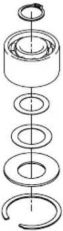
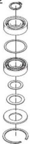
Pure mechanical assembly diagram showing a series of concentric rings and a curved end (no text or symbols)B1 MPA2304 LW ROS Spindle Bearing Kit Code: 8994022811
natural_image
Technical line drawing of a mechanical component with no visible text or symbolsC MPA0798 Air Inlet Kit
Code: 8993018811
B2 MPA0807 LW ROS Spindle Bearing Kit
Code: 8993019611

natural_image
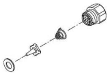
Technical line drawing of a mechanical component with mounting holes and a cylindrical shaft (no text or symbols)D MPA0988 CV Swivel Fitting Kit
Code: 8993006611
natural_image
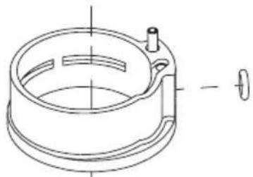
Technical line drawing of a mechanical component with no visible text or symbolsE MPA0994 Cylinder & O-ring Kit Code: 8993009211
natural_image
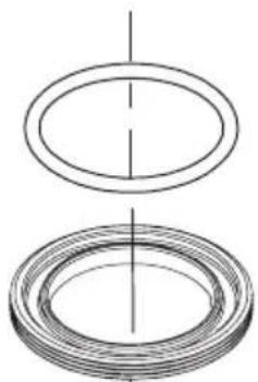
Two technical line drawings of concentric circular components, no text or symbols presentF MPA0993 Lock Ring & O-ring Kit Code: 8993007911

natural_image
Three sequential diagrammatic steps showing concentric circular components with a small circular top (no text or symbols)G MPA0799 Endplate Bearing Kit Code: 8993019811
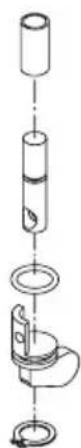
H MPA0800 Speed Valve Kit
Code: 8993019011
natural_image
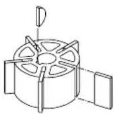
Technical line drawing of a mechanical component with no visible text or symbols| MPA0801 Rotor, Vanes & Key Kit Code: 8993017711
natural_image
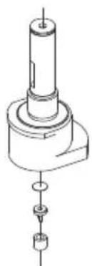
Technical line drawing of a mechanical assembly with no visible text or symbolsJ MPA2154 Shaft Balancer Kit 2.5mm orbit Code: 8993014311 MPA2892 Shaft Balancer Kit 5.0mm orbit Code: 8993014321
KMPA0984 Lever Kit 2.5 mm orbit
Code: 8993010911
MPA0983 Lever Kit 5.0 mm orbit
Code: 8993010811
Stefan Sjöberg, Executive Vice President

Brugsanvisning
Please Read and Comply with
1) General Industry Safety & Health Regulations, Part 1910, OSHA 2206, available from: Superintendent of Documents; Government Printing Office; Washington DC 20402.
2) Safety Code for Portable Air Tools, ANSI B186.1 available from: American National Standards Institute, Inc.; 1430 Broadway; New York, New York 10018.
3) State and Local Regulations.
Proper Use of Tool
This sander is designed for sanding all types of materials i.e. metals, wood, stone, plastics, etc. using abrasive designed for this purpose. Do not use this sander for any other purpose than that specified without consulting the manufacturer or the manufacturer's authorized supplier. Do not use back-up pads that have a working speed less than 12,000 rpm free speed.
Work Stations
The tool is intended to be operated as a hand-held tool. It is always recommended that the tool be used when standing on a solid floor. It can be used in any position, but before any such use the operator must be in a secure position and have a firm grip and footing, and be aware that the sander can develop a torque reaction. See the section "Operating Instructions".
Putting the Tool into Service
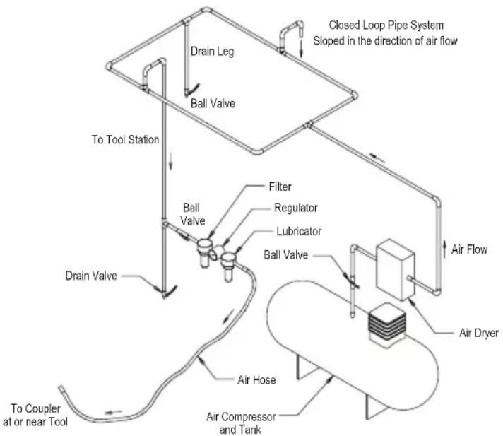
Use a clean lubricated air supply that will give a measured air pressure at the tool of 6.2 bar (90 psig) bar when the tool is running with the lever fully depressed. It is recommended to use an approved 10 mm (3/8 in.) x 8 m (25 ft) maximum length airline. It is recommended that the tool be connected to the air supply as shown in Figure 1.
Do not connect the tool to the airline system without incorporating an easy to reach and operate air shut-off valve. The air supply should be lubricated. It is strongly recommended that an air filter, regulator and lubricator (FRL) be used as shown in Figure 1 as this will supply clean, lubricated air at the correct pressure to the tool. Details of such equipment can be obtained from your supplier. If such equipment is not used then the tool should be manually lubricated.
To manually lubricate the tool, disconnect the airline and put two or three drops of suitable pneumatic motor lubricating oil such as Fuji Kosan FK-20, Mobil ALMO 525 or Shell TORCULA® 32 into the hose end (inlet) of the machine. Reconnect the tool to the air supply and run the tool slowly for a few seconds to allow air to circulate the oil. If the tool is used frequently, lubricate it on a daily basis or lubricate it if the tool starts to slow or lose power. It is recommended that the air pressure at the tool is 6.2 bar (90 psig) while the tool is running. The tool can run at lower pressures but never higher than 6.2 bar (90 psig).
Operating Instructions
1) Read all instructions before using this tool. All operators must be fully trained in its use and aware of these safety rules. All servicing and repairs must be carried out by trained personnel.
2) Make sure the tool is disconnected from the air supply. Select a suitable abrasive and secure it to the back-up pad. Be careful and center the abrasive on the back-up pad.
3) Always wear the required safety equipment when using this tool.
4) When sanding always place the tool on the work then start the tool. Always remove the tool from the work before stopping. This will prevent gouging of the work due to excess speed of the abrasive.
5) Always disconnect the air supply from the sander before fitting, adjusting or removing the abrasive or back-up pad.
6) Always adopt a firm footing and/or position and be aware of the torque reaction developed by the sander.
7) Use only correct spare parts.
8) Always ensure that the material to be sanded is firmly fixed to prevent its movement.
9) Check the hose and fittings regularly for wear. Do not carry the tool by its hose; always be careful to prevent the tool from being started when carrying the tool with the air supply connected.
10) Dust can be highly combustible. The vacuum dust collection bag should be cleaned or replaced daily. Cleaning or replacing of the bag also assures optimum performance.
11) Do not exceed the maximum recommended air pressure. Use safety equipment as recommended.
12) The tool is not electrically insulated. Do not use where there is a possibility of coming into contact with live electricity, gas pipes, water pipes, etc. Check the working area before use.
13) Take care to avoid entanglement of the moving parts of the tool with clothing, ties, hair, cleaning rags, etc. If entangled, it will cause the body to be pulled towards the work, and moving parts of the machine and can be very dangerous.
14) Keep hands clear of the spinning pad during use.
15) If the tool appears to malfunction, stop using it immediately and arrange for servicing and repair.
16) Do not allow the tool to free-speed without taking precautions to protect any persons or objects from the loss of the abrasive or pad.
flowchart
graph TD
    A["Air Dryer"] --> B["Air Compressor and Tank"]
    B --> C["Air Hose"]
    C --> D["Drain Valve"]
    D --> E["To Tool Station"]
    E --> F["Ball Valve"]
    F --> G["Filter"]
    G --> H["Lubricator"]
    H --> I["Regulator"]
    I --> J["Blind Valve"]
    J --> K["Blind Leg"]
    K --> L["Closed Loop Pipe System Sloped in the direction of air flow"]
    style A fill:#f9f,stroke:#333
    style B fill:#ccf,stroke:#333
    style C fill:#cfc,stroke:#333
    style D fill:#fcc,stroke:#333
    style E fill:#cff,stroke:#333
    style F fill:#ffc,stroke:#333
    style G fill:#cfc,stroke:#333
    style H fill:#fcc,stroke:#333
    style I fill:#ffc,stroke:#333
    style J fill:#cfc,stroke:#333
    style K fill:#fcc,stroke:#333
    style L fill:#ffc,stroke:#333
Product Configuration/Specifications: 12,000 rpm Random Orbital Sander
| Orbit | Pad Size mm (in.) | Vacuum Type | Model Number | Product Net Weight kg (pound) | Heigh mm (inch) | Length mm (inch) | Power watts (HP) | Air Consumption LPM (scfm) | *Noise Level dBA | *Vibration Level m/s2 | *Uncertainty K m/s2 |
| 2,5 mm (3/32 in,) | 77 mm (3 in,) | Non-Vacuum | ROS325NV 0,51 (1,12) | 78,7 (3,10) | 124,3 (4,90) | 209 (0,28) | 481 (17) 76,5 3,04 | 0,80 | |||
| Central Vacuum | ROS325CV 0,57 (1,26) | 78,7 (3,10) | 186,2 (7,30) | 209 (0,28) | 481(17) 74,5 3,20 | 0,81 | |||||
| Self-Gen Vacuum | ROS325DB 0,59 (1,30) | 78,7 (3,10) | 190,1 (7,50) | 209 (0,28) | 481 (17) 84,5 2,66 | 0,76 | |||||
| 5,0 mm (3/16 in,) | 77 mm (3 in,) | Non-Vacuum | ROS350NV 0,60 (1,33) | 85,0 (3,35) | 124,3 (4,90) | 209 (0,28) | 481 (17) 74,0 2,70 | 1,40 | |||
| Central Vacuum | ROS350CV 0,66 (1,47) | 85,0 (3,35) | 186,2 (7,30) | 209 (0,28) | 481(17) 76,0 2,30 | 1,20 | |||||
| Self-Gen Vacuum | ROS350DB 0,68 (1,51) | 85,0 (3,35) | 190,1 (7,50) | 209 (0,28) | 481 (17) 88,0 2,80 | 1,40 | |||||
The noise test is carried out in accordance with EN ISO 15744:2008 - Hand-held non-electric power tools -- Noise measurement code -- Engineering method (grade 2) and EN ISO 11203:2009 Acoustics-Noise emitted by machinery and equipment-Determination of emission sound pressure levels at a work station and other specified positions from the sound power level.
The vibration test is carried out in accordance with EN ISO 28927-3, Hand-held portable power tools – Test method for evaluation of vibration emission – Part 3: Polishers and rotary, orbital and random orbital sanders.
Specifications subject to change without prior notice.
*The values stated in the table are from laboratory testing in conformity with stated codes and standards and are not sufficient for risk evaluation. Values measured in a particular work place may be higher than the declared values. The actual exposure values and amount of risk or harm experienced to an individual is unique to each situation and depends upon the surrounding environment, the way in which the individual works, the particular material being worked, work station design as well as upon the exposure time and the physical condition of the user. KWH Mirka, Ltd. cannot be held responsible for the consequences of using declared values instead of actual exposure values for any individual risk assessment.
Further occupational health and safety information can be obtained from the following websites:
https://osha.europa.eu/en (Europe)
http://www.osha.gov (USA)
Troubleshooting Guide
| Symptom Possible Cause Solution | ||
| Low power and/or low free speed. | Insufficient air pressure. Check air line pressure at the inlet of the Sander while the tool is running at free speed. It must be 6.2 Bar (90 psig/620 kPa). | |
| Clogged muffler(s). See the “Housing Disassembly” section for Muffler removal. The Item 38 Muffler can be back-flushed with a clean, suitable cleaning solution until all contaminants and obstructions have been removed. If the Muffler cannot be properly cleaned then replace it. Replace Item 39 Muffler Insert (see the “Housing Assembly” section). | ||
| Plugged Inlet Screen. Clean the Inlet Screen with a clean, suitable cleaning solution. If the Screen cannot be cleaned, replace it. | ||
| One or more worn or broken Vanes. Install a complete set of new Vanes (all vanes must be replaced for proper operation). Coat all vanes with quality pneumatic tool oil. See “Motor Disassembly” and “Motor Assembly”. | ||
| Internal air leakage in the Motor Housing indicated by higher than normal air consumption and lower than normal speed. | Check for proper Motor alignment and Lock Ring engagement. Check for damaged O-Ring in Lock Ring groove. Remove Motor Assembly and Re-install the Motor Assembly. See “Motor Disassembly” and “Motor Assembly”. | |
| Motor parts worn. Overhaul Motor. Contact authorized Mirka Service Center. | ||
| Worn or broken Spindle Bearings. Replace the worn or broken Bearings. See “Shaft Balancer and Spindle Disassembly” and “Spindle Bearings, AirSHIELDTM and Shaft Balancer Assembly”. | ||
| Air leakage through the Speed Control and/or Valve Stem. | Dirty, broken or bent Valve Spring, Valve or Valve Seat. | Disassemble, inspect and replace worn or damaged parts. See steps 2 and 3 in “Housing Disassembly” and steps 2 and 3 in “Housing Assembly”. |
| Vibration/rough operation. | Incorrect Pad. Only use Pad sizes and weights designed for the machine. | |
| Addition of interface pad or other material. Only use abrasives and/or interfaces designed for the machine. Do not attach anything to the Sander Pad face that was not specifically designed to be used with the Pad and Sander. | ||
| Improper lubrication or build-up of foreign debris. | Disassemble the Sander and clean in a suitable cleaning solution. Reassemble the Sander. (See “Service Manual”.) | |
| Worn or broken rear or front Motor Bearing(s). | Replace the worn or broken Bearings. See “Motor Disassembly” and “Motor Assembly”. | |
| For vacuum machines it is possible to have too much vacuum while sanding on a flat surface, causing the pad to stick to the sanding surface. | For DB machines, add extra washer(s) to the pad spindle to increase the gap between the pad and shroud. For CV machines reduce vacuum through the vacuum system and/or add extra washer(s) to the pad. | |
https://osha.europa.eu/en (Europe)
http://www.osha.gov (USA)
Guide de dépannage
https://osha.europa.eu/en(유럽)
http://www.osha.gov(미국)
문제 해결 가이드
Stefan Sjöberg, Executive Vice President
Gebruiksaanwijzing
https://osha.europa.eu/en (Avrupa)
http://www.osha.gov (ABD)
| Declaration of conformityKWH Mirka Ltd.66850 Jeppo, Finland77 mm (3 in.) 12,000 rpm Random Orbital Sanders (See “Product Configuration/Specifications” Table for particular Model) to which this declaration relates is in conformity with the following standard(s) or other normative document(s) EN ISO 15744:2008. Following the provisions of 89/392/EEC as amended by 91/368/EEC & 93/44/EEC 93/68/EEC Directives and consolidating Directive 2006/42/EC | |||
 Jeppo 21.08.2014MIRKAPlace and date of issue CompanyStefan Sjöberg, CEO Jeppo 21.08.2014MIRKAPlace and date of issue CompanyStefan Sjöberg, CEO | |||
| Operator InstructionsIncludes – Please Read and Comply, Proper Use of Tool, Work Stations, Putting the Tool Into Service, Operating Instruc-tions, Product Configuration/Specifications Tables, Parts Page, Parts List, Sander Spare Parts Kits, Trouble Shooting Guide | ImportantRead these instructions care-fully before installing, operating, servicing or repairing this tool.Keep these instructions in a safe accessible location. |  | |
| Manufacturer/SupplierKWH Mirka Ltd.66850 Jeppo, FinlandTel: +358 20 760 2111Fax: +358 20 760 2290 | Required Personal Safety EquipmentSafety Glasses Breathing MasksSafety Gloves Ear Protection | ||
| Recommended Airline Size - Minimum10 mm 3/8 in | Recommended Maximum Hose Length8 meters 25 feet | Air PressureMaximum Working Pressure 6.2 bar 90 psigRecommended Minimum NA NA | |
Please Read and Comply with
1) General Industry Safety & Health Regulations, Part 1910, OSHA 2206, available from: Superintendent of Documents; Government Printing Office; Washington DC 20402
2) Safety Code for Portable Air Tools, ANSI B186.1 available from: American National Standards Institute, Inc.; 1430 Broadway; New York, New York 10018
3) State and Local Regulations.
Proper Use of Tool
This sander is designed for sanding all types of materials i.e. metals, wood, stone, plastics, etc. using abrasive designed for this purpose. Do not use this sander for any other purpose than that specified without consulting the manufacturer or the manufacturer's authorized supplier. Do not use back-up pads that have a working speed less than 12,000 rpm free speed.
Work Stations
The tool is intended to be operated as a hand held tool. It is always recommended that the tool be used when standing on a solid floor. It can be in any position but before any such use, the operator must be in a secure position having a firm grip and footing and be aware that the sander can develop a torque reaction. See the section "Operating Instructions".
Putting the Tool into Service
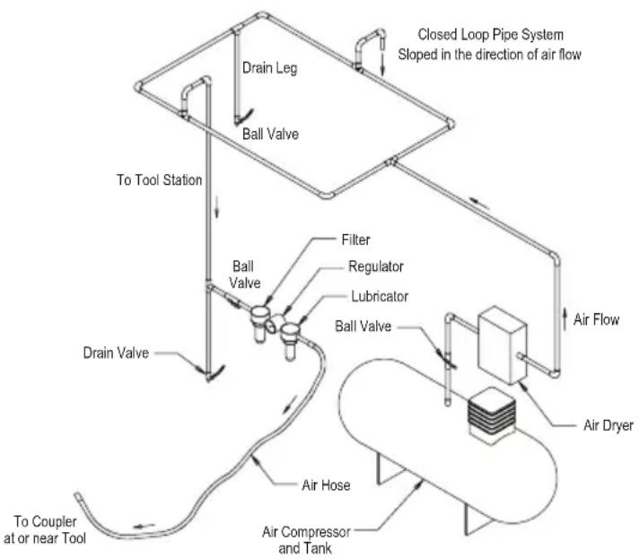
Use a clean lubricated air supply that will give a measured air pressure at the tool of 6.2 bar (90 psig) bar when the tool is running with the lever fully depressed. It is recommended to use an approved 10 mm (3/8 in.) x 8 m (25 ft) maximum length airline. It is recommended that the tool be connected to the air supply as shown in Figure 1.
Do not connect the tool to the airline system without incorporating an easy to reach and operate air shut off valve. The air supply should be lubricated. It is strongly recommended that an air filter, regulator and lubricator (FRL) be used as shown in Figure 1 as this will supply clean, lubricated air at the correct pressure to the tool. Details of such equipment can be obtained from your supplier. If such equipment is not used then the tool should be manually lubricated
To manually lubricate the tool, disconnect the airline and put 2 to 3 drops of suitable pneumatic motor lubricating oil such as Fuji Kosan FK-20, Mobil ALMO 525 or Shell TORCULA® 32 into the hose end (inlet) of the machine. Reconnect tool to the air supply and run tool slowly for a few seconds to allow air to circulate the oil. If the tool is used frequently, lubricate it on a daily basis or lubricate it if the tool starts to slow or lose power. It is recommended that the air pressure at the tool is 6.2 bar (90 psig) while the tool is running. The tool can run at lower pressures but never higher than 6.2 bar (90 psig.
Operating Instructions
1) Read all instructions before using this tool. All operators must be fully trained in its use and aware of these safety rules. All service and repair must be carried out by trained personnel.
2) Make sure the tool is disconnected from the air supply. Select a suitable abrasive and secure it to the back-up pad. Be careful and center the abrasive on the back-up pad.
3) Always wear required safety equipment when using this tool.
4) When sanding always place the tool on the work then start the tool. Always remove the tool from the work before stopping. This will prevent gouging of the work due to excess speed of the abrasive.
5) Always remove the air supply to the sander before fitting, adjusting or removing the abrasive or back-up pad.
6) Always adopt a firm footing and/or position and be aware of torque reaction developed by the sander.
7) Use only correct spare parts.
8) Always ensure that the material to be sanded is firmly fixed to prevent its movement.
9) Check hose and fittings regularly for wear. Do not carry the tool by its hose; always be careful to prevent the tool from being started when carrying the tool with the air supply connected.
10) Dust can be highly combustible. Vacuum dust collection bag should be cleaned or replaced daily. Cleaning or replacing of bag also assures optimum performance.
11) Do not exceed maximum recommended air pressure. Use safety equipment as recommended.
12) The tool is not electrically insulated. Do not use where there is a possibility of coming into contact with live electricity, gas pipes, water pipes, etc. Check the area of operation before operation.
13) Take care to avoid entanglement with the moving parts of the tool with clothing, ties, hair, cleaning rags, etc. If entangled, it will cause the body to be pulled towards the work and moving parts of the machine and can be very dangerous.
14) Keep hands clear of the spinning pad during use.
15) If the tool appears to malfunction, remove from use immediately and arrange for service and repair.
16) Do not allow the tool to free speed without taking precautions to protect any persons or objects from the loss of the abrasive or pad.
flowchart
graph TD
    A["Air Dryer"] --> B["Air Compressor and Tank"]
    B --> C["To Coupler at or near Tool"]
    C --> D["Drain Valve"]
    D --> E["Ball Valve"]
    E --> F["Filter"]
    F --> G["Lubricator"]
    G --> H["Regulator"]
    H --> I["Ball Valve"]
    I --> J["Sloped in the direction of air flow"]
    J --> K["Closed Loop Pipe System"]
    K --> L["Drain Leg"]
    L --> M["To Tool Station"]
Product Configuration/Specifications: 12,000 rpm Random Orbital Sander
| Orbit | Pad Size mm (in.) | Vacuum Type | Model Number | Product Net Weight kg (pound) | Heigh mm (inch) | Length mm (inch) | Power watts (HP) | Air Consumption LPM (scfm) | *Noise Level dBA | *Vibration Level m/s2 | *Uncertainty K m/s2 |
| 2,5 mm (3/32 in,) | 77 mm (3 in,) | Non-Vacuum | ROS325NV 0,51 (1,12) | 78,7 (3,10) | 124,3 (4,90) | 209 (0,28) | 481 (17) 76,5 3,04 | 0,80 | |||
| Central Vacuum | ROS325CV 0,57 (1,26) | 78,7 (3,10) | 186,2 (7,30) | 209 (0,28) | 481(17) 74,5 3,20 | 0,81 | |||||
| Self-Gen Vacuum | ROS325DB 0,59 (1,30) | 78,7 (3,10) | 190,1 (7,50) | 209 (0,28) | 481 (17) 84,5 2,66 | 0,76 | |||||
| 5,0 mm (3/16 in,) | 77 mm (3 in,) | Non-Vacuum | ROS350NV 0,60 (1,33) | 85,0 (3,35) | 124,3 (4,90) | 209 (0,28) | 481 (17) 74,0 2,70 | 1,40 | |||
| Central Vacuum | ROS350CV 0,66 (1,47) | 85,0 (3,35) | 186,2 (7,30) | 209 (0,28) | 481(17) 76,0 2,30 | 1,20 | |||||
| Self-Gen Vacuum | ROS350DB 0,68 (1,51) | 85,0 (3,35) | 190,1 (7,50) | 209 (0,28) | 481 (17) 88,0 2,80 | 1,40 | |||||
The noise test is carried out in accordance with EN ISO 15744:2008 - Hand-held non-electric power tools -- Noise measurement code -- Engineering method (grade 2) and EN ISO 11203:2009 Acoustics-Noise emitted by machinery and equipment-Determination of emission sound pressure levels at a work station and other specified positions from the sound power level.
The vibration test is carried out in accordance with EN ISO 28927-3, Hand-held portable power tools – Test method for evaluation of vibration emission — Part 3: Polishers and rotary, orbital and random orbital sanders.
Specifications subject to change without prior notice.
*The values stated in the table are from laboratory testing in conformity with stated codes and standards and are not sufficient for risk evaluation. Values measured in a particular work place may be higher than the declared values. The actual exposure values and amount of risk or harm experienced to an individual is unique to each situation and depends upon the surrounding environment, the way in which the individual works, the particular material being worked, work station design as well as upon the exposure time and the physical condition of the user. KWH Mirka, Ltd. cannot be held responsible for the consequences of using declared values instead of actual exposure values for any individual risk assessment.
Further occupational health and safety information can be obtained from the following websites:
https://osha.europa.eu/en (Europe)
http://www.osha.gov (USA)
Troubleshooting Guide
| Symptom Possible Cause Solution | ||
| Low Power and/or Low Free Speed | Insufficient Air Pressure Check air line pressure at the Inlet of the Sander while the tool is running at free speed. It must be 6.2 Bar (90 psig/620 kPa). | |
| Clogged Muffler(s) See the “Housing Disassembly” section for Muffler removal. The Item 38 Muffler can be back flushed with a clean, suitable cleaning solution until all contaminates and obstructions have been removed. If the Muffler can not be properly cleaned then replace it. Replace Item 39, Muffler Insert (See the “Housing Assembly” Section). | ||
| Plugged Inlet Screen Clean the Inlet Screen with a clean, suitable cleaning solution. If Screen does not come clean replace it. | ||
| One or more Worn or Broken Vanes Install a complete set of new Vanes (all vanes must be replaced for proper operation). Coat all vanes with quality pneumatic tool oil. See “Motor Disassembly” and “Motor Assembly”. | ||
| Internal air leakage in the Motor Housing indicated by higher than normal air consumption and lower than normal speed. | Check for proper Motor alignment and Lock Ring engagement. Check for damaged O-Ring in Lock Ring groove. Remove Motor Assembly and Re-Install the Motor Assembly. See “Motor Disassembly” and “Motor Assembly”. | |
| Motor Parts Worn Overhaul Motor. Contact authorized Mirka Service Center. | ||
| Worn or broken Spindle Bearings Replace the worn or broken Bearings. See “Shaft Balancer and Spindle Disassembly” and “Spindle Bearings, AirSHIELDTM and Shaft Balancer Assembly”. | ||
| Air leakage through the Speed Control and/or Valve Stem. | Dirty, broken or bent Valve Spring, Valve or Valve Seat. | Disassemble, inspect and replace wore or damaged parts. See Steps 2 and 3 in “Housing Disassembly” and Steps 2 and 3 in “Housing Assembly”. |
| Vibration/Rough Operation | Incorrect Pad Only use Pad Sizes and Weights designed for the machine. | |
| Addition of interface pad or other material | Only use abrasive and/or interface designed for the machine. Do not attach anything to the Sanders Pad face that was not specifically designed to be used with the Pad and Sander. | |
| Improper lubrication or buildup of foreign debris. | Disassemble the Sander and clean in a suitable cleaning solution. Assemble the Sander. (See “Service Manual”) | |
| Worn or broken Rear or Front Motor Bearing(s) | Replace the worn or broken Bearings. See “Motor Disassembly” and “Motor Assembly”. | |
| For vacuum machines it is possible to have too much vacuum while sanding on a flat surface causing the pad to stick to the sanding surface. | For SGV machines add extra washer(s) to the pad spindle to increase the gap between the pad and shroud. For CV machines reduce vacuum through the vacuum system and/or add extra washer(s) to the pad. | |
PONCEUSES ORBITALES
ALÉATOIRES LÉGÈRES
Mirka 12.000 rpm
DE 77 mm (3 po.)
https://osha.europa.eu/en (Europe)
http://www.osha.gov (USA)
geo
| Location | Marker | | -------- | ------ | | (Various points) | Black diamond marker |KWH MIRKA LTD
Finland
Brazil Mirka Brasil Ltda.
Canada Mirka Abrasives Canada Inc.
China Mirka Trading Shanghai Co., Ltd
Finland & Baltics KWH Mirka Ltd
France Mirka Abrasifs s.a.r.l.
Germany Mirka Schleifmittel GmbH
India Mirka India Pvt Ltd
Italy Mirka Italia s.r.l.
Mexico KWH Mirka Mexicana, S.A. de C.V.
Russia Mirka Rus LLC
Singapore Mirka Asia Pacific Pte Ltd
Spain KWH Mirka Ibérica S.A.U.
Sweden Mirka Scandinavia AB
Turkey Mirka Turkey Zimpara Ltd Şirketi
United Kingdom Mirka (UK) Ltd
USA Mirka Abrasives, Inc
For contact information,
please visit www.mirka.com
Quality from start to finish


Brand : Mirka
Model : ROS 325CV
Category : Grinder