
H 1105 VE - Grinder Flex - Free user manual and instructions
Find the device manual for free H 1105 VE Flex in PDF.

| Product type | Straight grinder |
| Brand | Flex |
| Model | H 1105 VE |
| Mains voltage | 230 V |
| Frequency | 50 Hz |
| Power consumption | 710 W |
| Power output | 420 W |
| Speed range | 2500 - 6500 rpm |
| Collet diameter | 40 mm |
| Tool holder | 3, 6, 8 mm, 1/4" |
| Protection class | II (double insulation) |
| Weight (without cable) | 2.1 kg |
| Sound pressure level | LpA 86 dB(A) |
| Sound power level | LWA 97 dB(A) |
| Vibration emission value | 3.1 m/s² (K=1.5 m/s²) |
| Speed presetting | Yes, thumbwheel |
| Overload circuit breaker | Yes, automatic |
| Maintenance | Cleaning with dry compressed air; repairs by authorized service center |
| Safety | Read the manual, wear PPE (goggles, ear protection) |
| Included accessories | Clamping chuck 6 mm, wrench, retaining claw |
| Intended use | Grinding and deburring of metal, precision work on molds |
Frequently Asked Questions - H 1105 VE Flex
User questions about H 1105 VE Flex
0 question about this device. Answer the ones you know or ask your own.
Ask a new question about this device
Download the instructions for your Grinder in PDF format for free! Find your manual H 1105 VE - Flex and take your electronic device back in hand. On this page are published all the documents necessary for the use of your device. H 1105 VE by Flex.
USER MANUAL H 1105 VE Flex
natural_image
Illustration of two electric drill heads with visible blades and wiring (no text or symbols)1 D r e h z a h l v o r w a h l
2 S c h a l t e r w i p p e
natural_image
Close-up of a mechanical component with a black arrow pointing to a textured rectangular slot (no text or symbols visible)natural_image
Close-up of a mechanical component with a downward arrow and textured internal structure (no text or symbols)Einmaulschlüssel 104.914
Manager Research & Development (R & D)
Symbols used in this manual ..... 13
For your safety 13
Noise and vibration 16
Technical specifications 17
Overview 18
Operating instructions 19
Maintenance and care 20
Disposal information 21
C€-Declaration of Conformity ..... 21
Exemption from liability 21
Symbols used in this manual

WARNING!
Denotes impending danger. Non-observance of this warning may result in death or extremely severe injuries.

CAUTION!
Denotes a possibly dangerous situation. Non-observance of this warning may result in slight injury or damage to property.

NOTE
Denotes application tips and important information.
Symbols on the power tool

To reduce the risk of injury, read the operating instructions!

Wear goggles!

Wear ear protection!

Disposal information for the oldmachine (see page 21)!
For your safety

WARNING!
Before using the power tool, please read and follow:
–these operating instructions,
-the "General safety instructions" on the handling of power tools in the enclosed booklet (leaflet-no.315.915),
–the currently valid site rules and the regulations for the prevention of accidents.
This power tool is state of the art and has been constructed in accordance with the acknowledged safety regulations. Nevertheless, when in use, the power tool may be a danger to life and limb of the user or a third party, or the power tool or other property may be damaged. The power tool may be operated only if it is
- a s i n t e n d e d ,
-in perfect working order.
Faults which impair safety must be repaired immediately.
Intended use
The straight grinder is designed
– for commercial use in industry and trade,
– for grinding and deburring metal,
– for use with tools and accessories which are indicated in this manual or recommended by the manufacturer.
H 1105 VE
- for finish grinding in mould construction using grinding pencils and flap wheel grinders,
– for use with lamellar grinders,
- for use exclusively with tools which are authorised to run at speeds up to 6,500 rpm.
H 1127 VE
– for use with corundum grinding pencils,
– for use exclusively with tools which are authorised to run at speeds up to 30,000 rpm.
Safety instructions

WARNING!
Read all safety instructions and other instructions. Failure to observe the safety instructions and other instructions may result in an electric shock, fire and/or serious injuries. Keep all safety instructions and other instructions in a safe place for the future.
■ This electric power tool must be used as a sander. Observe all safety information, instructions, diagrams and data which you receive with the power tool.
If you do not observe the following instructions, an electric shock, fire and/or serious injuries may occur.
■ This electric power tool is not suitable for use with sandpaper, wire brushes, or for polishing and cut-off grinding.
If the electric power tool is not used as intended, the user may be exposed to hazards and may be injured.
■ Never use accessories which the manufacturer did not intend or recommend especially for this electric power tool.
Just because you can attach the accessory to your electric power tool does not guarantee safe use.
■ The permitted speed of the insertion tool must be at least as high as the maximum speed indicated on the electric power tool.
An accessory which rotates faster than permitted may shatter and fly off.
■ Outer diameter and thickness of the insertion tool must correspond to the dimensions of the electric power tool.
Incorrectly measured insertion tools cannot be adequately shielded or controlled.
■ Sanding discs, sanding pads or other accessories must fit exactly on the grinding spindle of your electric power tool.
Insertion tools, which do not fit exactly on the grinding spindle of the electric power tool, rotate unevenly, vibrate violently and may result in loss of control.
■ Do not use any damaged insertion tools. Before use, always check insertion tools for splinters and cracks, sanding pad for cracks, wear and severe abrasion. If the electric power tool or the insertion tool is dropped, check for damage or use an undamaged insertion tool. When you have checked and inserted the tool, ensure that you and anybody in the vicinity remain outside the plane of the rotating insertion tool and leave the power tool running for one minute at maximum speed.
Damaged insertion tools usually break during this test time.
■ Wear personal protective equipment. Depending on the application, wear full face protection, eye protection or goggles. If appropriate, wear a dust mask, hearing protection, protective gloves and/or a special apron which protect you from small sanding and material particles.
You should protect your eyes from foreign objects which are ejected for different applications. Dust and respirator masks must filter the dust which is generated by the power tool for the particular application. If you are exposed to loud noise for a prolonged period, you may suffer hearing loss.
■ Ensure that other persons are situated at a safe distance from the work area. Anyone who enters the work area must wear personal protective equipment.
Fragments of the workpiece or broken insertion tools may fly off and cause injuries even outside the direct working area.
If the insertion tool is at risk of coming into contact with concealed power cables or the power cord itself, hold the power tool by the insulated grip surfaces only.
Contact with a live cable may also cause metal parts of the appliance to become live and result in an electric shock.
- Keep the power cord away from rotating insertion tools.
If you lose control of the appliance, the power cord could be severed or become caught and your hand or arm may strike the rotating insertion tool.
■ Never put down the electric power tool until the insertion tool has come to a standstill.
The rotating insertion tool may come into contact with the support surface, possibly resulting in you losing control of the electric power tool.
■ Never leave the electric power tool running while you are carrying it.
Your clothing may become caught by accidental contact with the rotating insertion tool which may then drill into your body.
■ Regularly clean the ventilation slots on your electric power tool.
The motor fan draws dust into the housing; a large build-up of metal dust may cause electrical hazards.
■ Never use the electric power tool near combustible materials.
Sparks may ignite these materials.
■ Never use insertion tools which require liquid coolants.
The use of water or other liquid coolants may result in electric shock.
Special safety instructions for sanding:
■ Use only those sanding tools authorised for use with your electric power tool and the guard designated for this sanding tool.
Sanding tools, which are not designated for use with the electric power tool, cannot be adequately shielded and are unsafe.
■ Sanding tools may be used for the recommended applications only.
For example: Never sand with the side area of a diamond sanding pad. Diamond sanding pads are designed to remove material with the underside of the sanding pad. If a lateral force is applied to these sanding tools, they may shatter.
■ Always use undamaged clamping flanges in the correct size and shape for the insertion tool you have selected.
Suitable flanges support the insertion tools and therefore reduce the risk of a break.
■ Do not use worn insertion tools from larger electric power tools.
Insertion tools for larger electric power tools are not designed for the higher speeds of smaller electric power tools and may break.
Recoil and appropriate safety instructions
Kickback is the sudden reaction to a pinched or snagged rotating insertion tool, such as a sanding disc, sanding pad, wire brush, etc.
Pinching or snagging may cause a rotating insertion tool to stop abruptly. As a result, an uncontrolled electric power tool is accelerated against the direction of rotation of the insertion tool at the blocking point.
For example, if a sanding disc is snagged or pinched by the workpiece, the edge of the sanding disc which is entering the workpiece may become caught and cause the sanding disc to break off or kick back. The sanding disc then moves towards or away from the operator, depending on the direction in which the disc is rotating at the point of pinching. Sanding discs may also break under these conditions.
A recoil occurs if the electric power tool is used incorrectly or improperly. A recoil can be prevented by appropriate precautions as described below.
■ Hold the electric power tool firmly and position your body and arms to allow you to absorb kickback forces. If fitted, always use the auxiliary handle to ensure the best possible control over the recoil forces or reaction torques when acceleration occurs.
The operator can control kickback and reaction forces by taking appropriate precautions.
- Keep your hands away from the rotating insertion tool.
The insertion tool may kickback over your hand.
- Keep your body out of the area into which the electric power tool moves when a recoil occurs.
Kickback propels the electric power tool in the direction opposite to the movement of the sanding disc at the point of pinching.
■ Work especially carefully near corners, sharp edges, etc. Prevent the insertion tool from recoiling off the workpiece and jamming.
The rotating insertion tool has a tendency to snag on corners, sharp edges or if it bounces.
This causes a loss of control or kickback.
■ Do not use a chain or toothed saw blade. Such insertion tools frequently cause a kickback or the loss of control of the electric power tool.
Additional safety instructions
It is not recommended to sand lead paint. Lead paint should be removed by a specialist only.
■ Do not work on materials which release hazardous substances (e.g. asbestos). Take precautions if hazardous, combustible or explosive dust is likely to occur. Wear protective dust mask. Use dust extraction system.
■ When working, hold the electric power tool firmly with both hands and ensure that you have a secure footing. The electric power tool is controlled more securely if held with both hands.
- Do not use the electric power tool if it has a damaged power cord. Do not touch the damaged power cord and pull out the mains plug if the power cord is damaged during work. Damaged power cords increase the risk of an electric shock.

DAMAGE TO PROPERTY!
■ The mains voltage and the voltage specifications on the rating plate must correspond.
Noise and vibration
The noise and vibration values have been determined in accordance with EN 60745. The A evaluated noise level of the power tool is typically:
| Sound pressure L_pA [dB(A)] | Sound power L_WA [dB(A)] | |
| H 1105 VE | 86 97 | |
| H 1127 VE | 90 101 | |
| Uncertainty K = 3 dB | ||
Total vibration value (when grinding metal surfaces):
| Emission value a_h [m/s2] | ||
| H 1105 VE 3.1 | ||
| H 1127 VE 3.2 | ||
| Uncertainty K [m/s2] | 1.5 1.8 | |

WARNING!
The indicated measurements refer to new power tools. Daily use causes the noise and vibration values to change.

NOTE
The vibration emission level given in this information sheet has been measured in accordance with a standardised test given in EN 60745 and may be used to compare one tool with another. It may be used for a preliminary assessment of exposure. The declared vibration emission level represents the main applications of the tool. However if the tool is used for different applications, with different accessories or poorly maintained, the vibration emission may differ. This may significantly increase the exposure level over the total working period. For a precise estimation of the vibration load the times should also be considered during which the power tool is switched off or even running, but not actually in use. This may significantly decrease the exposure level over the total working period. Identify additional safety measures to protect the operator from the effects of vibration such as: maintain the tool and the accessories, keep the hands warm, organisation of work patterns.

CAUTION!
Wear ear protection at a sound pressure above 85 dB(A).
Technical specifications
| Machine type | Straight grinder | ||
| H 1105 VE H 11 | 27 VE | ||
| Max. grinding tool diameter synthetic resin/ceramic | mm 30 30 | ||
| Max. grinding tool diameter fibre-reinforced | mm 50 50 | ||
| Mains voltage V/Hz 230/50 230/50 | |||
| Power input W 710 710 | |||
| Power output W 420 420 | |||
| Speed r.p.m. 2,500–6,500 10,000–30,000 | |||
| Clamping neck diameter | mm 40 40 | ||
| Tool holder | 3, 6, 8 mm, 14" | 3, 6, 8 mm, 14" | |
| Protection class | ☐/II | ☐/II | |
| Weight (without power cord) | kg | 2.1 | 1.8 |
Overview
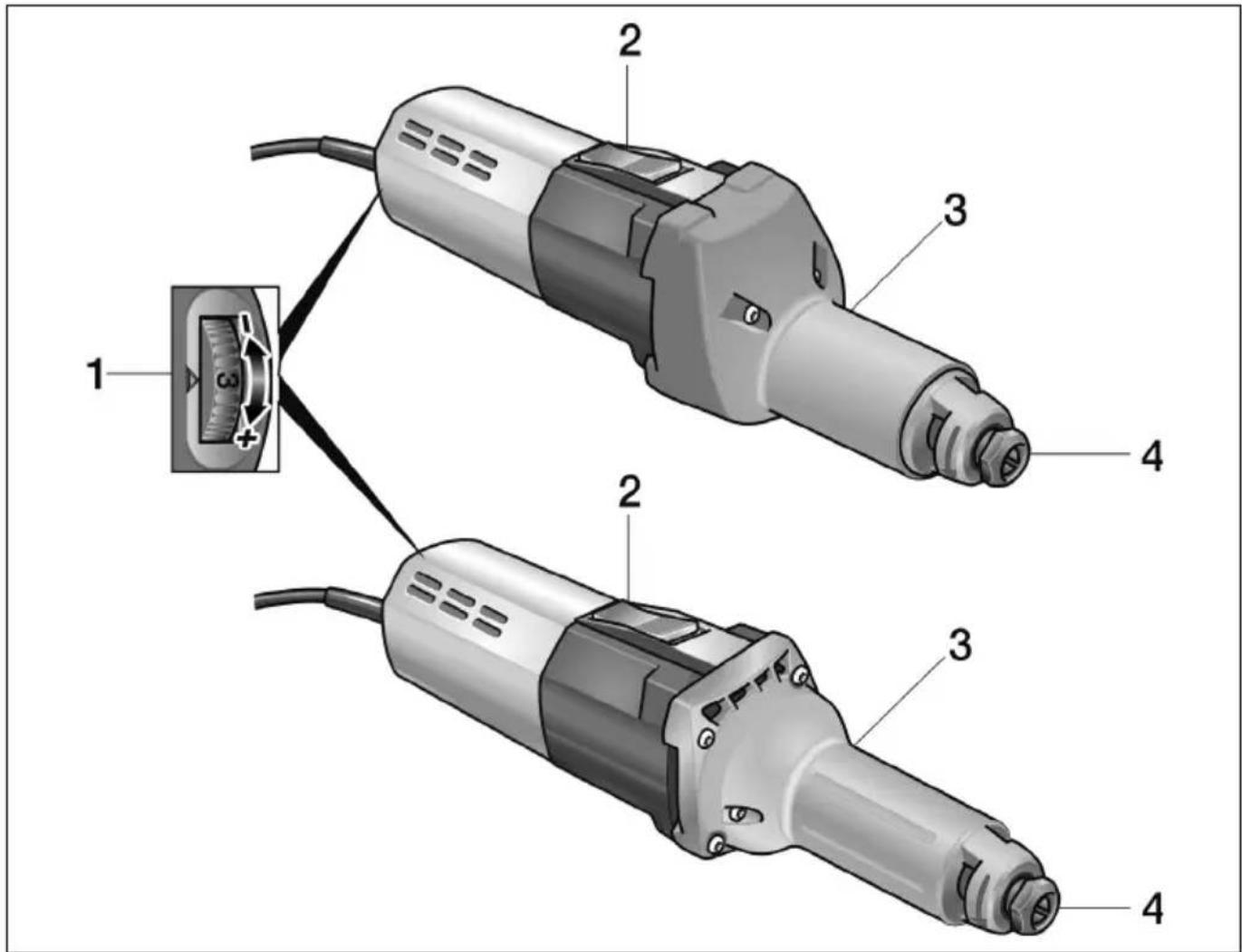
1 Preselecting the speed
2 Switch rocker
For switching on and off.
With notched position for continuous operation.
3 Spindle neck
4 Chuck with clamping nut
Operating instructions

WARNING!
Before performing any work on the electric power tool, pull out the mains plug.

CAUTION!
The available mains voltage and the voltage specifications on the rating plate must be the same.
Before switching on the power tool
■ Unpack power tool and accessories and check that no parts are missing or damaged.
■ Insert grinding tool.
Inserting and changing the grinding tools
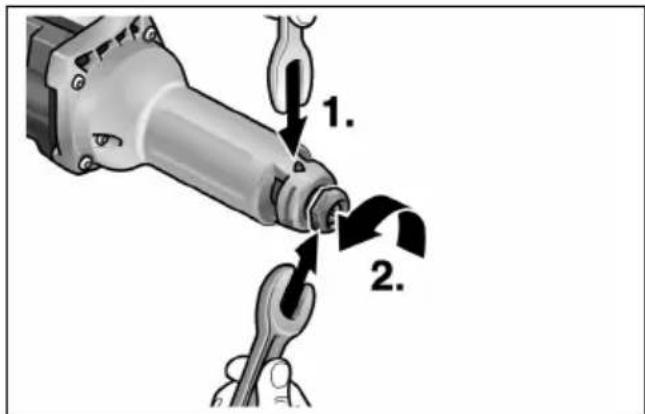
■ Hold the grinding spindle (1.) using the size 14 stopper claw. Turn the size 19 single head wrench anti-clockwise and loosen the clamping nut (2.).
■ Insert the grinding tool all the way into the chuck (3.).
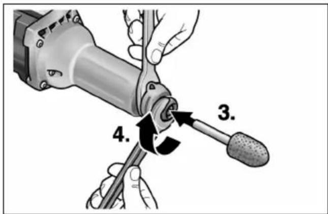
■ Turn the size 19 single head wrench (4.) clockwise and tighten the clamping nut.

NOTE
Use undamaged, true running grinding tools only. If required, use a whetstone or replace grinding tool.
Preselecting the speed
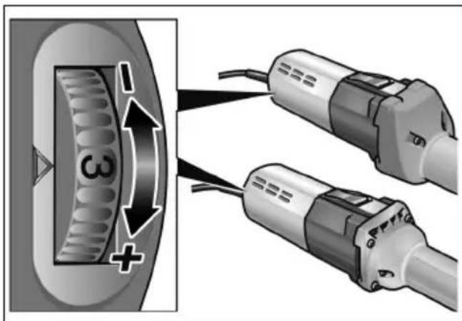
To set the operating speed, move the dial to the required value.
Switching the electric power tool on and off
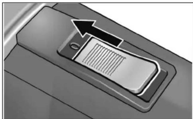
Brief operation without engaged switch rocker:
natural_image
Close-up of a mechanical component with a black arrow pointing to a textured rectangular slot (no text or symbols visible)■ Push the switch rocker forwards and hold in position.
■ To switch off the power tool, release the switch rocker.
Continuous operation with engaged switch rocker:

CAUTION!
Following a power failure, the switched on electric power tool will start running again.
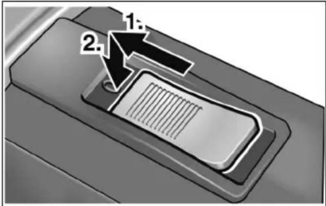
■ Push the switch rocker forwards (1.) and engage by pressing the front end (2.).
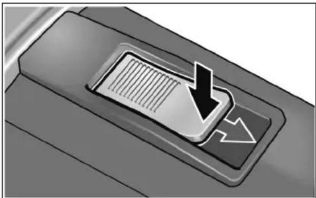
Switch off the machine:
natural_image
Close-up of a mechanical component with a downward arrow and textured internal structure (no text or symbols)■ To switch off the power tool, release the switch rocker by pressing the rear end.
Overload protection
If an extremely brief overload occurs, the overload protection prevents damage to the motor by automatically switching the device off.
For further information on the manufacturer's products go to www.flex-tools.com.
Operating instructions
■ Do not place the grinding tool on the workpiece until the power tool has reached full speed.
■ To obtain a good grinding result, move the grinding tool evenly over the surface which is to be ground down. Do not apply excessive pressure.
■ When the power tool is switched off, the grinding tool continues running briefly.
The H 1105 VE can also be used as a support grinder. For this purpose remove the handle and clamp the power tool in an appropriate device (clamping diameter 40 mm).
Maintenance and care

WARNING!
Before performing any work on the electric power tool, pull out the mains plug.
Cleaning

WARNING!
Donot use water or liquid detergents.
■ Regularly blow out the housing interior and motor with dry compressed air.
■ Clean the guard and pivoted edge segment using dry compressed air.
Repairs
Repairs may be carried out by an authorised customer service centre only.

NOTE
During the warranty period do not loosen the screws on the motor housing. Non-compliance will deem the guarantee obligations of the manufacturer null and void.
Spare parts and accessories
Accessories Article number
| 6 mm chuck 228.656 |
| Stopper claw 254.917 |
| Single head wrench 104.914 |
Other accessories, in particular insertion tools, can be found in the manufacturer's catalogues.
Exploded drawings and spare-part lists can be found on our homepage:
www.flex-tools.com
Disposal information

WARNING!
Render redundant power tools unusable byremoving the power cord.
EU countries only
Do not throw electric power tools into the household waste!
In accordance with the European Directive 2012/19/EU on Waste Electrical and Electronic Equipment and transposition into national law used electric power tools must be collected separately and recycled in an environmentally friendly manner.

NOTE
Please ask your dealer about disposal options!
CE -Declaration of Conformity
We declare under our sole responsibility that the product described under “Technical specifications” conforms to the following standards or normative documents:
EN 60745 in accordance with the regulations of the directives 2014/30/EU, 2006/42/EC, 2011/65/EU.
Responsible for technical documents: FLEX-Elektrowerkzeuge GmbH, R & D Bahnhofstrasse 15, D-71711 Steinheim/Murr
Manager Research & Development (R & D)
Klaus Peter WeinperEckhard Rühle Head of Quality Department (QD)
30.06.2015
Exemption from liability
The manufacturer and his representative are not liable for any damage and lost profit due to interruption in business caused by the product or by an unusable product.
The manufacturer and his representative are not liable for any damage which was caused by improper use of the power tool or by use of the power tool with products from other manufacturers.
Table des matières
natural_image
Close-up of a mechanical component with a highlighted arrow pointing to a textured rectangular area (no text or symbols visible)natural_image
Close-up of a mechanical component with a downward arrow and textured internal structure (no text or symbols)Manager Research & Development (R & D)
Klaus Peter WeinperEckhard Rühle Head of Quality Department (QD)
30.06.2015
natural_image
Close-up of a mechanical component with an arrow pointing to a textured rectangular slot (no text or symbols visible)natural_image
Close-up of a mechanical component with a downward arrow and textured internal structure (no text or symbols)Manager Research & Development (R & D)
Klaus Peter WeinperEckhard F Head of Quality Department (QD)
30.06.2015
natural_image
Close-up of a mechanical component with a highlighted arrow pointing to a textured rectangular area (no text or symbols visible)natural_image
Close-up of a mechanical component with a downward arrow and internal grid pattern (no text or symbols)Manager Research & Development (R & D) 30.06.2015
Klaus Peter WeinperEckhard Rühle Head of Quality Department (QD)
natural_image
Close-up of a mechanical component with a highlighted arrow pointing to a textured surface (no text or symbols visible)natural_image
Close-up of a mechanical component with a downward arrow and textured internal structure (no text or symbols)EN 60745 de acordo com as determinações das directivas 2014/30/UE, 2006/42/CE, 2011/65/UE.
Manager Research & Development (R & D)
Klaus Peter WeinperEckhard Rühle Head of Quality Department (QD)
30.06.2015
natural_image
Close-up of a car door handle with a mounted device and an arrow pointing to it (no text or symbols visible)natural_image
Close-up of a mechanical component with a downward arrow and textured internal structure (no text or symbols)Manager Research & Development (R & D)
Klaus Peter WeinperEckhard F Head of Quality Department (QD)
natural_image
Close-up of a car door handle with a mounted device and arrow indicating upward motion (no text or symbols)■ Skub vippekontakten fremad og hold den fast.
■ Slip vippekontakten for at slukke.
Konstant drift med indgreb:

FORSIGTIG!
natural_image
Close-up of a mechanical component with a downward arrow and internal grid pattern (no text or symbols)Manager Research & Development (R & D)
Klaus Peter WeinperEckhard F Head of Quality Department (QD)
30.06.2015
natural_image
Close-up of a mechanical component with a black arrow pointing to a textured internal structure (no text or symbols visible)natural_image
Close-up of a mechanical component with a downward arrow and textured internal structure (no text or symbols)Manager Research & Development (R & D)
Klaus Peter WeinperEckhard F
Head of Quality
Department (QD)
30.06.2015
natural_image
Close-up of a car front panel with an arrow pointing to a slot (no text or symbols visible)natural_image
Close-up of a mechanical component with a downward arrow and textured surface (no text or symbols)Manager Research & Development (R & D)
Klaus Peter WeinperEckhard F
Head of Quality
Department (QD)
30.06.2015
natural_image
Close-up of a car's front panel with a right-pointing arrow indicating left vent (no text or symbols)natural_image
Close-up of a mechanical component with a downward arrow and textured internal structure (no text or symbols)natural_image
Close-up of a mechanical component with a highlighted arrow pointing to a textured rectangular area (no text or symbols visible)natural_image
Close-up of a car's air vent with a down arrow indicating airflow or ventilation (no text or symbols)Manager Research &
Development (R & D)
30.06.2015
Klaus Peter WeinperEckhard F
Head of Quality
Department (QD)
natural_image
Close-up of a mechanical component with a highlighted arrow pointing to a textured rectangular area (no text or symbols visible)natural_image
Close-up of a mechanical component with a downward arrow and textured internal structure (no text or symbols)Manager Research & Development (R & D)
Klaus Peter WeinperEckhard F Head of Quality Department (QD)
30.06.2015
natural_image
Close-up of a mechanical component with a highlighted rectangular slot and an arrow indicating direction (no text or symbols)natural_image
Close-up of a car's air vent with a down arrow indicating airflow or ventilation (no text or symbols)Manager Research & Development (R & D)
Klaus Peter WeinperEckhard F
Head of Quality Department (QD)
natural_image
Close-up of a car door handle with a black arrow pointing to a slot (no text or symbols visible)natural_image
Close-up of a mechanical component with a downward arrow and internal grid pattern (no text or symbols)Manager Research & Development (R & D)
Klaus Peter WeinperEckhard F Head of Quality Department (QD)
30.06.2015
natural_image
Close-up of a mechanical component with a highlighted arrow pointing to a textured rectangular area (no text or symbols visible)natural_image
Close-up of a mechanical component with a downward arrow and textured internal structure (no text or symbols)Manager Research &
Development (R & D)
30.06.2015
1 Pöörete eelvalik
2 Lüliti
natural_image
Close-up of a car's front panel with a black arrow pointing to a slot, no text or symbols visiblenatural_image
Close-up of a car's air vent with a black arrow pointing to the vent, showing airflow or airflow direction (no text or symbols)Manager Research & Development (R & D)
Klaus Peter WeinperEckhard F
Head of Quality
Department (QD)
30.06.2015
natural_image
Close-up of a mechanical component with a black arrow pointing to a textured rectangular area (no text or symbols visible)natural_image
Close-up of a car's air vent with a down arrow and ventilation grille (no text or symbols)Manager Research & Development (R & D)
Klaus Peter WeinperEckhard F Head of Quality Department (QD)
30.06.2015
natural_image
Close-up of a mechanical component with a black arrow pointing to a textured rectangular area (no text or symbols visible)natural_image
Close-up of a car's air vent with a down arrow and ventilation grille (no text or symbols)Manager Research & Development (R & D)
Klaus Peter WeinperEckhard F
Head of Quality
Department (QD)
natural_image
Close-up of a mechanical component with an arrow pointing to a textured internal structure (no text or symbols visible)natural_image
Close-up of a mechanical component with a downward arrow and textured internal structure (no text or symbols)Manager Research & Development (R & D)
Klaus Peter WeinperEckhard F
Head of Quality Department (QD)
30.06.2015


- Symbols used in this manual
- WARNING!
- CAUTION!
- NOTE
- Symbols on the power tool
- For your safety
- Intended use
- H 1105 VE
- H 1127 VE
- Safety instructions
- Special safety instructions for sanding:
- Recoil and appropriate safety instructions
- Additional safety instructions
- DAMAGE TO PROPERTY!
- Noise and vibration
- Overview
- Operating instructions
- Before switching on the power tool
- Inserting and changing the grinding tools
- Preselecting the speed
- Switching the electric power tool on and off
- Continuous operation with engaged switch rocker:
- Switch off the machine:
- Overload protection
- Maintenance and care
- Cleaning
- Repairs
- Spare parts and accessories
- Disposal information
- CE -Declaration of Conformity
- Exemption from liability
- Table des matières
- Konstant drift med indgreb:
- FORSIGTIG!
Brand : Flex
Model : H 1105 VE
Category : Grinder