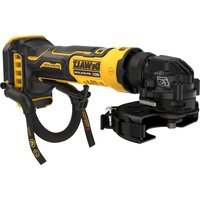
DCS438 - Grinder DEWALT - Free user manual and instructions
Find the device manual for free DCS438 DEWALT in PDF.


User questions about DCS438 DEWALT
0 question about this device. Answer the ones you know or ask your own.
Ask a new question about this device
Download the instructions for your Grinder in PDF format for free! Find your manual DCS438 - DEWALT and take your electronic device back in hand. On this page are published all the documents necessary for the use of your device. DCS438 by DEWALT.
USER MANUAL DCS438 DEWALT
English (original instructions) 32
text_image
Technical diagram of a DeWalt solar power supply with numbered components and labeled partsFig. B
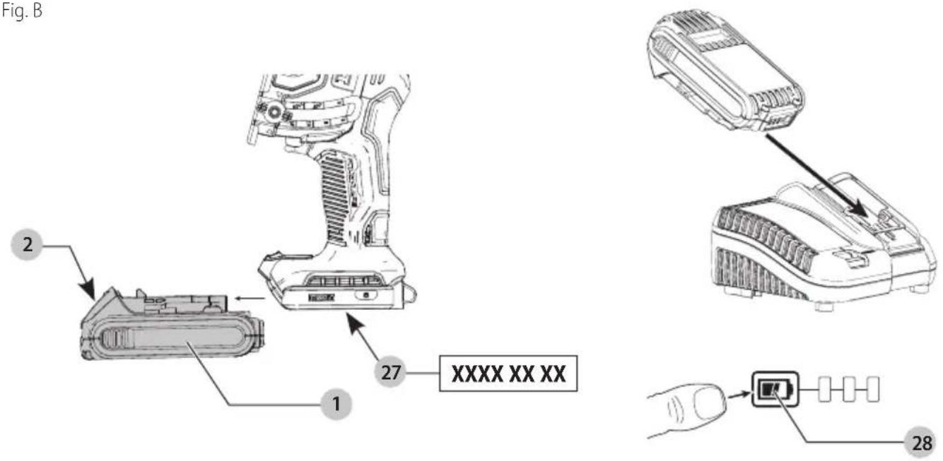
Fig. C
text_image
13 18 17 19 16 15Fig. D
text_image
Technical diagram of a vehicle's wheel assembly with labeled parts and directional arrowsFig. E
text_image
E DTM/NTAINT 12 20 9 11 21Fig. F

text_image
F 8 22 23 23 22Fig. G Fig. H
text_image
3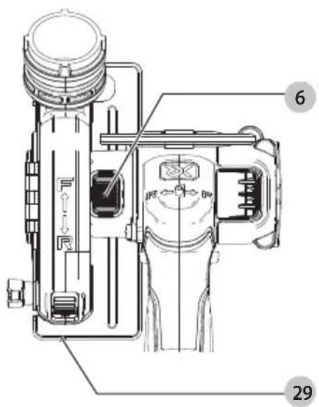
text_image
Technical diagram of a mechanical device with numbered parts and labeled componentsFig.1
text_image
26 25 24AFSTIKKERVÆRKT∅J
DCS438
Tillykke!
Border risiko for brand.
| Batterier Opladere/opladningstider (minutter)*** | |||||||||||||
| Kat # V | DC | Ah Vægt (kg) | DCB104 DCB107 DCB112 DCB113 DCB115 DCB116 DCB117 DCB118 DCB132 DCB119 | ||||||||||
| DCB546 | 18/54 | 6,0/2,0 | 1,08 | 60 | 270 | 170 | 140 | 90 | 80 | 40 | 60 | 90 | X |
| DCB547 | 18/54 | 9,0/3,0 | 1,46 | 75* | 420 | 270 | 220 | 135* | 110* | 60 | 75* | 135* | X |
| DCB548 | 18/54 | 12,0/4,0 | 1,46 | 120 | 540 | 350 | 300 | 180 | 150 | 80 | 120 | 180 | X |
| DCB549 | 18/54 | 15,0/5,0 | 2,12 | 125 | 730 | 450 | 380 | 230 | 170 | 90 | 125 | 230 | X |
| DCB181 | 18 | 1,5 | 0,35 | 22 | 70 | 45 | 35 | 22 | 22 | 22 | 22 | 22 | 45 |
| DCB182 | 18 | 4,0 | 0,61 | 60/40** | 185 | 120 | 100 | 60 | 60/45** | 60/40** | 60/40** | 60 | 120 |
| DCB183/B/G | 18 | 2,0 | 0,40 | 30 | 90 | 60 | 50 | 30 | 30 | 30 | 30 | 30 | 60 |
| DCB184/B/G | 18 | 5,0 | 0,62 | 75/50** | 240 | 150 | 120 | 75 | 75/60** | 75/50** | 75/50** | 75 | 150 |
| DCB185 | 18 | 1,3 | 0,35 | 22 | 60 | 40 | 30 | 22 | 22 | 22 | 22 | 22 | 40 |
| DCB187 | 18 | 3,0 | 0,54 | 45 | 140 | 90 | 70 | 45 | 45 | 45 | 45 | 45 | 90 |
| DCB189 | 18 | 4,0 | 0,54 | 60 | 185 | 120 | 100 | 60 | 60 | 60 | 60 | 60 | 120 |
| DCBP034 | 18 | 1,7 | 0,32 | 27 | 82 | 50 | 40 | 27 | 27 | 27 | 27 | 27 | 50 |
natural_image
Technical line drawing of a mechanical component with no visible text or symbolsInstallation of Tool Connect™ Chip
natural_image
Technical line drawing of a mechanical component with mounting holes and a handle (no text or symbols)You have chosen a DEWALT tool. Years of experience, thorough product development and innovation make DEWALT one of the most reliable partners for professional power tool users.
Technical Data
| DCS438 | ||
| Voltage V | DC | 18 |
| Type 1 | ||
| Battery type Li-lon | ||
| No-load/rated speed min | -1 | 20000 |
| Wheel diameter mm 76 | ||
| Wheel thickness (max) mm 2.2 | ||
| Spindle diameter mm 10 | ||
| Spindle length mm 43 | ||
| Weight (without battery pack) kg 0.94 | ||
| Noise values and/or vibration values (triax vector sum) according to EN60745-2-3: | ||
| L_PA (emission sound pressure level) dB(A) 87 | ||
| L_WA (sound power level) | dB(A) 98 | |
| K (uncertainty for the given sound level) | dB(A) | 3 |
| Vibration emission value a_h = | m/s2 | 3.3 |
| Uncertainty K = | m/s2 | 1.5 |
The vibration and/or noise emission level given in this information sheet has been measured in accordance with a standardised test given in EN60745 and may be used to compare one tool with another. It may be used for a preliminary assessment of exposure.
WARNING: The declared vibration and/or noise emission leads represents the main applications of the tool. However if the tool is used for different applications, with different accessories or poorly maintained, the vibration and/or noise emission may differ. This may significantly increase the exposure level over the total working period.
An estimation of the level of exposure to vibration and/or noise should also take into account the times when the tool is switched off or when it is running but not actually doing the job. This may significantly reduce the exposure level over the total working period.
Identify additional safety measures to protect the operator from the effects of vibration and/or noise such as: maintain the tool and the accessories, keep the hands warm (relevant for vibration), organisation of work patterns.
EC-Declaration of Conformity
Machinery Directive

Cut Off Tool
DCS438
DEWALT declares that these products described under
Technical Data are in compliance with:
2006/42/EC, EN60745-1:2009 + A11:2010; EN60745-2-22:2011 + A11:2013.
These products also comply with Directive 2014/30/EU and 2011/65/EU. For more information, please contact DEWALT at the following address or refer to the back of the manual.
The undersigned is responsible for compilation of the technical file and makes this declaration on behalf of DEWALT.
text_image
M. Georg Hartley R. R. and Hartley R. R. andMarkus Rompel
Vice-President Engineering, PTE-Europe
65510, Idstein, Germany
24.09.2021
| Batteries Chargers/Charge | Times (Minutes)*** | ||||||||||||
| Cat # V | DC | Ah Weight (kg) | DCB104 DCB107 DCB112 DCB113 DCB115 DCB116 DCB117 DCB118 DCB132 DCB119 | ||||||||||
| DCB546 | 18/54 | 6.0/2.0 | 1.08 | 60 | 270 | 170 | 140 | 90 | 80 | 40 | 60 | 90 | X |
| DCB547 | 18/54 | 9.0/3.0 | 1.46 | 75* | 420 | 270 | 220 | 135* | 110* | 60 | 75* | 135* | X |
| DCB548 | 18/54 | 12.0/4.0 | 1.46 | 120 | 540 | 350 | 300 | 180 | 150 | 80 | 120 | 180 | X |
| DCB549 | 18/54 | 15.0/5.0 | 2.12 | 125 | 730 | 450 | 380 | 230 | 170 | 90 | 125 | 230 | X |
| DCB181 | 18 | 1.5 | 0.35 | 22 | 70 | 45 | 35 | 22 | 22 | 22 | 22 | 22 | 45 |
| DCB182 | 18 | 4.0 | 0.61 | 60/40** | 185 | 120 | 100 | 60 | 60/45** | 60/40** | 60/40** | 60 | 120 |
| DCB183/B/G | 18 | 2.0 | 0.40 | 30 | 90 | 60 | 50 | 30 | 30 | 30 | 30 | 30 | 60 |
| DCB184/B/G | 18 | 5.0 | 0.62 | 75/50** | 240 | 150 | 120 | 75 | 75/60** | 75/50** | 75/50** | 75 | 150 |
| DCB185 | 18 | 1.3 | 0.35 | 22 | 60 | 40 | 30 | 22 | 22 | 22 | 22 | 22 | 40 |
| DCB187 | 18 | 3.0 | 0.54 | 45 | 140 | 90 | 70 | 45 | 45 | 45 | 45 | 45 | 90 |
| DCB189 | 18 | 4.0 | 0.54 | 60 | 185 | 120 | 100 | 60 | 60 | 60 | 60 | 60 | 120 |
| DCBP034 | 18 | 1.7 | 0.32 | 27 | 82 | 50 | 40 | 27 | 27 | 27 | 27 | 27 | 50 |
*Date code 201811475B or later
**Date code 201536 or later
***Battery charge times matrix provided for guidance only; charge times will vary depending on temperature and condition of batteries.
DECLARATION OF CONFORMITY THE SUPPLY OF MACHINERY (SAFETY) REGULATIONS 2008

Cut Off Tool DCS438
DEWALT declares that these products described under
Technical Data are in compliance with:
The Supply of Machinery (Safety) Regulations, 2008, S.I.
2008/1597 (as amended),
EN60745-1:2009 + A11:2010; EN60745-2-22:2011 + A11:2013.
These products conform to the following UK Regulations:
Electromagnetic Compatibility Regulations, 2016, S.I.2016/1091 (as amended).
The Restriction of the Use of Certain Hazardous Substances in Electrical and Electronic Equipment Regulations 2012, S.I. 2012/3032 (as amended).
For more information, please contact DEWALT at the following address or refer to the back of the manual.
The undersigned is responsible for compilation of the technical file and makes this declaration on behalf of DEWALT.
text_image
E EKarl Evans
Vice President Professional Power Tools EANZ GTS
DEWALT UK, 270 Bath Road, Slough
Berkshire, SL1 4DX
England
24.09.2021

WARNING: To reduce the risk of injury, read the instruction manual.
Definitions: Safety Guidelines
The definitions below describe the level of severity for each signal word. Please read the manual and pay attention to these symbols.
DANGER: Indicates an imminently hazardous situation which, if not avoided, will result in death or serious injury.
WARNING: Indicates a potentially hazardous situation when, if not avoided, could result in death or serious injury.
CAINTION: Indicates a potentially hazardous situation which, if not avoided, may result in minor or moderate injury.
NOTICE: Indicates a practice not related to personal injury which, if not avoided, may result in property damage.
Diodes risk of electric shock.
Dicates risk of fire.
GENERAL POWER TOOL SAFETY WARNINGS
WARNING: Read all safety warnings, instructions, indications and specifications provided with this power tool. Failure to follow all instructions listed below may result in electric shock, fire and/or serious injury.
SAVE ALL WARNINGS AND INSTRUCTIONS FOR FUTURE REFERENCE
The term "power tool" in the warnings refers to your mains-operated (corded) power tool or battery-operated (cordless) power tool.
1) Work Area Safety
a) Keep work area clean and well lit. Cluttered or dark areas invite accidents.
b) Do not operate power tools in explosive atmospheres, such as in the presence of flammable liquids, gases or dust. Power tools create sparks which may ignite the dust or fumes.
c) Keep children and bystanders away while operating a power tool. Distractions can cause you to lose control.
2) Electrical Safety
a) Power tool plugs must match the outlet. Never modify the plug in any way. Do not use any adapter plugs with earthed (grounded) power tools.
Unmodified plugs and matching outlets will reduce risk of electric shock.
b) Avoid body contact with earthed or grounded surfaces, such as pipes, radiators, ranges and refrigerators. There is an increased risk of electric shock if your body is earthed or grounded.
c) Do not expose power tools to rain or wet conditions. Water entering a power tool will increase the risk of electric shock.
d) Do not abuse the cord. Never use the cord for carrying, pulling or unplugging the power tool. Keep cord away from heat, oil, sharp edges or moving parts. Damaged or entangled cords increase the risk of electric shock.
e) When operating a power tool outdoors, use an extension cord suitable for outdoor use. Use of a cord suitable for outdoor use reduces the risk of electric shock.
f) If operating a power tool in a damp location is unavoidable, use a residual current device (RCD) protected supply. Use of an RCD reduces the risk of electric shock.
3) Personal Safety
a) Stay alert, watch what you are doing and use common sense when operating a power tool. Do not use a power tool while you are tired or under the influence of drugs, alcohol or medication. A moment of inattention while operating power tools may result in serious personal injury.
b) Use personal protective equipment. Always wear eye protection. Protective equipment such as a dust mask, non-skid safety shoes, hard hat or hearing protection used for appropriate conditions will reduce personal injuries.
c) Prevent unintentional starting. Ensure the switch is in the off-position before connecting to power source and/or battery pack, picking up or carrying the tool. Carrying power tools with your finger on the switch or energising power tools that have the switch on invites accidents.
d) Remove any adjusting key or wrench before turning the power tool on. A wrench or a key left attached to a rotating part of the power tool may result in personal injury.
e) Do not overreach. Keep proper footing and balance at all times. This enables better control of the power tool in unexpected situations.
f) Dress properly. Do not wear loose clothing or jewellery. Keep your hair and clothing away from moving parts. Loose clothes, jewellery or long hair can be caught in moving parts.
g) If devices are provided for the connection of dust extraction and collection facilities, ensure these are connected and properly used. Use of dust collection can reduce dust-related hazards.
h) Do not let familiarity gained from frequent use of tools allow you to become complacent and ignore tool safety principles. A careless action can cause severe injury within a fraction of a second.
4) Power Tool Use and Care
a) Do not force the power tool. Use the correct power tool for your application. The correct power tool will do the job better and safer at the rate for which it was designed.
b) Do not use the power tool if the switch does not turn it on and off. Any power tool that cannot be controlled with the switch is dangerous and must be repaired.
c) Disconnect the plug from the power source and/or remove the battery pack, if detachable, from the power tool before making any adjustments, changing accessories, or storing power tools. Such preventive safety measures reduce the risk of starting the power tool accidentally.
d) Store idle power tools out of the reach of children and do not allow persons unfamiliar with the power tool or these instructions to operate the power tool. Power tools are dangerous in the hands of untrained users.
e) Maintain power tools and accessories. Check for misalignment or binding of moving parts, breakage of parts and any other condition that may affect the power tool's operation. If damaged, have the power tool repaired before use. Many accidents are caused by poorly maintained power tools.
f) Keep cutting tools sharp and clean. Properly maintained cutting tools with sharp cutting edges are less likely to bind and are easier to control.
g) Use the power tool, accessories and tool bits etc. in accordance with these instructions, taking into account the working conditions and the work to be performed. Use of the power tool for operations different from those intended could result in a hazardous situation.
h) Keep handles and grasping surfaces dry, clean and free from oil and grease. Slippery handles and grasping surfaces do not allow for safe handling and control of the tool in unexpected situations.
5) Battery Tool Use and Care
a) Recharge only with the charger specified by the manufacturer. A charger that is suitable for one type of battery pack may create a risk of fire when used with another battery pack.
b) Use power tools only with specifically designated battery packs. Use of any other battery packs may create a risk of injury and fire.
c) When battery pack is not in use, keep it away from other metal objects, like paper clips, coins, keys, nails, screws or other small metal objects, that can make a connection from one terminal to another. Shorting the battery terminals together may cause burns or a fire.
d) Under abusive conditions, liquid may be ejected from the battery; avoid contact. If contact accidentally occurs, flush with water. If liquid contacts eyes, additionally seek medical help. Liquid ejected from the battery may cause irritation or burns.
e) Do not use a battery pack or tool that is damaged or modified. Damaged or modified batteries may exhibit unpredictable behaviour resulting in fire, explosion or risk of injury.
f) Do not expose a battery pack or tool to fire or excessive temperature. Exposure to fire or temperature above 130 °C may cause explosion.
g) Follow all charging instructions and do not charge the battery pack or tool outside the temperature range specified in the instructions. Charging improperly or at temperatures outside the specified range may damage the battery and increase the risk of fire.
6) Service
a) Have your power tool serviced by a qualified repair person using only identical replacement parts. This will ensure that the safety of the power tool is maintained.
b) Never service damaged battery packs. Service of battery packs should only be performed by the manufacturer or authorized service providers.
CUT-OFF MACHINE SAFETY WARNINGS
a) The guard provided with the tool must be securely attached to the power tool and positioned for maximum safety, so the least amount of wheel is exposed towards the operator. Position yourself and bystanders away from the plane of the rotating wheel. The guard helps to protect operator from broken wheel fragments and accidental contact with wheel.
b) Use only bonded reinforced or diamond cut-off wheels for your power tool. Just because an accessory can be attached to your power tool, it does not assure safe operation.
c) The rated speed of the accessory must be at least equal to the maximum speed marked on the power tool. Accessories running faster than their rated speed can break and fly apart.
d) Wheels must be used only for recommended applications. For example: do not grind with the side of cut-off wheel. Abrasive cut-off wheels are intended for peripheral grinding, side forces applied to these wheels may cause them to shatter.
e) Always use undamaged wheel flanges that are of correct diameter for your selected wheel. Proper
wheel flanges support the wheel thus reducing the possibility of wheel breakage.
f) Do not use worn down reinforced wheels from larger power tools. Wheels intended for a larger power tool are not suitable for the higher speed of a smaller tool and may burst.
g) The outside diameter and the thickness of your accessory must be within the capacity rating of your power tool. Incorrectly sized accessories cannot be adequately guarded or controlled.
h) The arbour size of wheels and flanges must properly fit the spindle of the power tool. Wheels and flanges with arbour holes that do not match the mounting hardware of the power tool will run out of balance, vibrate excessively and may cause loss of control.
i) Do not use damaged wheels. Before each use, inspect the wheels for chips and cracks. If power tool or wheel is dropped, inspect for damage or install an undamaged wheel. After inspecting and installing the wheel, position yourself and bystanders away from the plane of the rotating wheel and run the power tool at maximum no load speed for one minute. Damaged wheels will normally break apart during this test time.
j) Wear personal protective equipment. Depending on application, use face shield, safety goggles or safety glasses. As appropriate, wear dust mask, hearing protectors, gloves and shop apron capable of stopping small abrasive or workpiece fragments. The eye protection must be capable of stopping flying debris generated by various operations. The dust mask or respirator must be capable of filtering particles generated by your operation. Prolonged exposure to high intensity noise may cause hearing loss.
k) Keep bystanders a safe distance away from work area. Anyone entering the work area must wear personal protective equipment. Fragments of workpiece or of a broken wheel may fly away and cause injury beyond immediate area of operation.
1) Hold the power tool by insulated gripping surfaces only, when performing an operation where the cutting accessory may contact hidden wiring. Cutting accessory contacting a "live" wire may make exposed metal parts of the power tool "live" and could give the operator an electric shock.
m) Never lay the power tool down until the accessory has come to a complete stop. The spinning wheel may grab the surface and pull the power tool out of your control.
n) Do not run the power tool while carrying it at your side. Accidental contact with the spinning accessory could snag your clothing, pulling the accessory into your body.
o) Regularly clean the power tool's air vents. The motor's fan will draw the dust inside the housing and
excessive accumulation of powdered metal may cause electrical hazards.
p) Do not operate the power tool near flammable materials. Sparks could ignite these materials.
q) Do not use accessories that require liquid coolants. Using water or other liquid coolants may result in electrocution or shock.
FURTHER SAFETY INSTRUCTIONS FOR ABRASIVE CUTTING-OFF OPERATIONS
Kickback and Related Warnings
Kickback is a sudden reaction to a pinched or snagged rotating wheel, backing pad, brush or any other accessory. Pinching or snagging causes rapid stalling of the rotating accessory which in turn causes the uncontrolled power tool to be forced in the direction opposite of the accessory's rotation at the point of the binding.
For example, if an abrasive wheel is snagged or pinched by the workpiece, the edge of the wheel that is entering into the pinch point can dig into the surface of the material causing the wheel to climb out or kick out. The wheel may either jump toward or away from the operator, depending on direction of the wheel's movement at the point of pinching. Abrasive wheels may also break under these conditions.
Kickback is the result of power tool misuse and/or incorrect operating procedures or conditions and can be avoided by taking proper precautions as given below:
a) Maintain a firm grip on the power tool and position your body and arm to allow you to resist kickback forces. Always use auxiliary handle, if provided, for maximum control over kickback or torque reaction during start-up. The operator can control torque reaction or kickback forces, if proper precautions are taken.
b) Never place your hand near the rotating accessory. Accessory may kickback over your hand.
c) Do not position your body in line with the rotating wheel. Kickback will propel the tool in direction opposite to the wheel's movement at the point of snagging.
d) Use special care when working corners, sharp edges etc. Avoid bouncing and snagging the accessory.
Corners, sharp edges or bouncing have a tendency to snag the rotating accessory and cause loss of control or kickback.
e) Do not attach a saw chain, woodcarving blade, segmented diamond wheel with a peripheral gap greater than 10 mm or toothed saw blade. Such blades create frequent kickback and loss of control.
f) Do not "jam" the wheel or apply excessive pressure. Do not attempt to make an excessive depth of cut. Overstressing the wheel increases the loading and susceptibility to twisting or binding of the wheel in the cut and the possibility of kickback or wheel breakage.
g) When wheel is binding or when interrupting a cut for any reason, switch off the power tool and hold
the power tool motionless until the wheel comes to a complete stop. Never attempt to remove the wheel from the cut while the wheel is in motion otherwise kickback may occur. Investigate and take corrective action to eliminate the cause of wheel binding.
h) Do not restart the cutting operation in the workpiece. Let the wheel reach full speed and carefully re-enter the cut. The wheel may bind, walk up or kickback if the power tool is restarted in the workpiece.
i) Support panels or any oversized workpiece to minimize the risk of wheel pinching and kickback.
Large workpieces tend to sag under their own weight. Supports must be placed under the workpiece near the line of cut and near the edge of the workpiece on both sides of the wheel.
j) Use extra caution when making a "pocket cut" into existing walls or other blind areas. The protruding wheel may cut gas or water pipes, electrical wiring or objects that can cause kickback.
Additional Safety Warnings for Abrasive Cutting-Off Operations:
a) This power tool is intended to function as a cut-off tool. Read all safety warnings, instructions, illustrations and specifications provided with this power tool. Failure to follow all instructions listed below may result in electric shock, fire and/or serious injury.
b) Operations such as grinding, sanding, wire brushing, or polishing are not recommended to be performed with this power tool. Operations for which the power tool was not designed may create a hazard and cause personal injury.
c) Do not use accessories which are not specifically designed and recommended by the tool manufacturer. Just because the accessory can be attached to your power tool, it does not assure safe operation.
d) The outside diameter and the thickness of your accessory must be within the capacity rating of your power tool. Incorrectly sized accessories cannot be adequately guarded or controlled.
e) The arbour size of wheels, flanges, backing pads or any other accessory must properly fit the spindle of the power tool. Accessories with arbour holes that do not match the mounting hardware of the power tool will run out of balance, vibrate excessively and may cause loss of control.
f) Set the depth of cut for no more than necessary. The less wheel exposed, the less chance of binding and kickback. Before cutting, be sure adjust shoe assembly is tight.
g) Do not force the tool. Forcing a cut off tool reduces control and cutting efficiency.
h) Do not use this tool as a table saw.
i) Firmly secure the workpiece.
j) Wear protective clothing and wash exposed areas with soap and water. Allowing dust to get into your mouth, eyes, or lay on the skin may promote absorption of harmful chemicals. Direct particles away from face and body.
k) Use the appropriate dust extractor vacuum to remove the vast majority of static and airborne dust. Failure to remove static and airborne dust could contaminate the working environment or pose an increased health risk to the operator and those in close proximity.
1) Use clamps or other practical ways to secure and support the workpiece to a stable platform. Holding the work by hand or against your body is unstable and may lead to loss of control and injury.
m) Air vents often cover moving parts and should be avoided. Loose clothes, jewelry or long hair can be caught in moving parts.
CAUTION: When not in use, place tool on its side on a single surface where it will not cause a tripping or falling hazard. Some tools with large battery packs will stand upright on the battery pack but may be easily knocked over.
n) When using segmented diamond wheels, use only diamond wheels with a peripheral gap not greater than 10 mm and negative rake angle.
Residual Risks
In spite of the application of the relevant safety regulations and the implementation of safety devices, certain residual risks cannot be avoided. These are:
- Impairment of hearing.
- Risk of personal injury due to flying particles.
- Risk of burns due to accessories becoming hot during operation.
- Risk of personal injury due to prolonged use.
SAVE THESE INSTRUCTIONS
Chargers
DEWALT chargers require no adjustment and are designed to be as easy as possible to operate.
Electrical Safety
The electric motor has been designed for one voltage only. Always check that the battery pack voltage corresponds to the voltage on the rating plate. Also make sure that the voltage of your charger corresponds to that of your mains.

Your DEWALTcharger is double insulated in accordance with EN60335; therefore no earth wire is required.
If the supply cord is damaged, it must be replaced only by DEWALT or an authorised service organisation.
Mains Plug Replacement (U.K. & Ireland Only)
If a new mains plug needs to be fitted:
• Safely dispose of the old plug.
- Connect the brown lead to the live terminal in the plug.
- Connect the blue lead to the neutral terminal.
WARNING: No connection is to be made to the earth terminal.
Follow the fitting instructions supplied with good quality plugs. Recommended fuse: 3 A.
Using an Extension Cable
An extension cord should not be used unless absolutely necessary. Use an approved extension cable suitable for the power input of your charger (see Technical Data). The minimum conductor size is 1 mm ^2 ; the maximum length is 30 m.
When using a cable reel, always unwind the cable completely.
Important Safety Instructions for All Battery Chargers
SAVE THESE INSTRUCTIONS: This manual contains important safety and operating instructions for compatible battery chargers (refer to Technical Data).
- Before using charger, read all instructions and cautionary markings on charger, battery pack, and product using battery pack.
WARNING: Shock hazard. Do not allow any liquid to get inside charger. Electric shock may result.
WARNING: We recommend the use of a residual current device with a residual current rating of 30mA or less.
CANTION: Burn hazard. To reduce the risk of injury, damage only DEWALT rechargeable batteries. Other types of batteries may burst causing personal injury and damage.
CAUTION: Children should be supervised to ensure that they do not play with the appliance.
NOTICE: Under certain conditions, with the charger plugged into the power supply, the exposed charging contacts inside the charger can be shorted by foreign material. Foreign materials of a conductive nature such as, but not limited to, steel wool, aluminum foil or any buildup of metallic particles should be kept away from charger cavities. Always unplug the charger from the power supply when there is no battery pack in the cavity. Unplug charger before attempting to clean.
- DO NOT attempt to charge the battery pack with any chargers other than the ones in this manual. The charger and battery pack are specifically designed to work together.
• These chargers are not intended for any uses other than charging DEWALT rechargeable batteries. Any other uses may result in risk of fire, electric shock or electrocution. - Do not expose charger to rain or snow.
- Pull by plug rather than cord when disconnecting charger. This will reduce risk of damage to electric plug and cord.
-
Make sure that cord is located so that it will not be stepped on, tripped over, or otherwise subjected to damage or stress.
-
Do not use an extension cord unless it is absolutely necessary. Use of improper extension cord could result in risk of fire, electric shock, or electrocution.
- Do not place any object on top of charger or place the charger on a soft surface that might block the ventilation slots and result in excessive internal heat.
Place the charger in a position away from any heat source. The charger is ventilated through slots in the top and the bottom of the housing.
- Do not operate charger with damaged cord or plug—have them replaced immediately.
- Do not operate charger if it has received a sharp blow, been dropped, or otherwise damaged in any way. Take it to an authorised service centre.
- Do not disassemble charger; take it to an authorised service centre when service or repair is required. Incorrect reassembly may result in a risk of electric shock, electrocution or fire.
- In case of damaged power supply cord, the supply cord must be replaced immediately by the manufacturer, its service agent or similar qualified person to prevent any hazard.
- Disconnect the charger from the outlet before attempting any cleaning. This will reduce the risk of electric shock. Removing the battery pack will not reduce this risk.
- NEVER attempt to connect two chargers together.
- The charger is designed to operate on standard 230V household electrical power. Do not attempt to use it on any other voltage. This does not apply to the vehicular charger.
Charging a Battery (Fig. B)
- Plug the charger into an appropriate outlet before inserting battery pack.
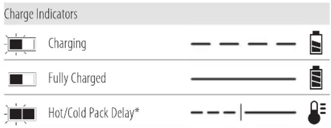
- Insert the battery pack 5 into the charger, making sure the battery pack is fully seated in the charger. The red (charging) light will blink repeatedly indicating that the charging process has started.
- The completion of charge will be indicated by the red light remaining ON continuously. The battery pack is fully charged and may be used at this time or left in the charger. To remove the battery pack from the charger, push the battery release button 2 on the battery pack.
NOTE: To ensure maximum performance and life of lithium-ion battery packs, charge the battery pack fully before first use.
Charger Operation
Refer to the indicators below for the charge status of the battery pack.
text_image
Charge Indicators Charging Fully Charged Hot/Cold Pack Delay** The red light will continue to blink, but a yellow indicator light will be illuminated during this operation. Once the battery pack has reached an appropriate temperature, the yellow light will turn off and the charger will resume the charging procedure. The compatible charger(s) will not charge a faulty battery pack. The charger will indicate faulty battery by refusing to light.
NOTE: This could also mean a problem with a charger. If the charger indicates a problem, take the charger and battery pack to be tested at an authorised service centre.
Hot/Cold Pack Delay
When the charger detects a battery pack that is too hot or too cold, it automatically starts a Hot/Cold Pack Delay, suspending charging until the battery pack has reached an appropriate temperature. The charger then automatically switches to the pack charging mode. This feature ensures maximum battery pack life.
A cold battery pack will charge at a slower rate than a warm battery pack. The battery pack will charge at that slower rate throughout the entire charging cycle and will not return to maximum charge rate even if the battery pack warms.
The DCB118 charger is equipped with an internal fan designed to cool the battery pack. The fan will turn on automatically when the battery pack needs to be cooled. Never operate the charger if the fan does not operate properly or if ventilation slots are blocked. Do not permit foreign objects to enter the interior of the charger.
Electronic Protection System
XR Li-Ion tools are designed with an Electronic Protection System that will protect the battery pack against overloading, overheating or deep discharge.
The tool will automatically turn off if the Electronic Protection System engages. If this occurs, place the lithium-ion battery pack on the charger until it is fully charged.
Wall Mounting
These chargers are designed to be wall mountable or to sit upright on a table or work surface. If wall mounting, locate the charger within reach of an electrical outlet, and away from a corner or other obstructions which may impede air flow. Use the back of the charger as a template for the location of the mounting screws on the wall. Mount the charger securely using drywall screws (purchased separately) at least 25.4 mm long with a screw head diameter of 7–9 mm, screwed into wood to an optimal depth leaving approximately 5.5 mm of the screw exposed. Align the slots on the back of the charger with the exposed screws and fully engage them in the slots.
Charger Cleaning Instructions
WARNING: Shock hazard. Disconnect the charger from the AC outlet before cleaning. Dirt and grease may be removed from the exterior of the charger using a cloth or soft non-metallic brush. Do not use water or any cleaning solutions. Never let any liquid get inside the tool; never immerse any part of the tool into a liquid.
Battery Packs
Important Safety Instructions for All Battery Packs
When ordering replacement battery packs, be sure to include catalogue number and voltage.
The battery pack is not fully charged out of the carton. Before using the battery pack and charger, read the safety instructions below. Then follow charging procedures outlined.
READ ALL INSTRUCTIONS
- Do not charge or use battery in explosive atmospheres, such as in the presence of flammable liquids, gases or dust. Inserting or removing the battery from the charger may ignite the dust or fumes.
- Never force battery pack into charger. Do not modify battery pack in any way to fit into a non-compatible charger as battery pack may rupture causing serious personal injury.
• Charge the battery packs only in DEWALT chargers. - DO NOT splash or immerse in water or other liquids.
- Do not store or use the tool and battery pack in locations where the temperature may fall below 4 °C (39.2 °F) (such as outside sheds or metal buildings in winter), or reach or exceed 40 °C (104 °F) (such as outside sheds or metal buildings in summer).
- Do not incinerate the battery pack even if it is severely damaged or is completely worn out. The battery pack can explode in a fire. Toxic fumes and materials are created when lithium-ion battery packs are burned.
- If battery contents come into contact with the skin, immediately wash area with mild soap and water. If battery liquid gets into the eye, rinse water over the open eye for 15 minutes or until irritation ceases. If medical attention is needed, the battery electrolyte is composed of a mixture of liquid organic carbonates and lithium salts.
- Contents of opened battery cells may cause respiratory irritation. Provide fresh air. If symptoms persist, seek medical attention.
WARNING: Burn hazard. Battery liquid may be flammable is exposed to spark or flame.
WARNING: Never attempt to open the battery pack for any reason. If battery pack case is cracked or damaged, do not insert into charger. Do not crush, drop or damage battery pack. Do not use a battery pack or charger that has received a sharp blow, been dropped, run over or damaged in any way (i.e., pierced with a nail, hit with a hammer, stepped on). Electric shock or electrocution may result. Damaged battery packs should be returned to service centre for recycling.
WARNING: Fire hazard. Do not store or carry the battery pack so that metal objects can contact exposed battery terminals. For example, do not place the battery pack in aprons, pockets, tool boxes, product kit boxes, drawers, etc., with loose nails, screws, keys, etc.
CAUTION: When not in use, place tool on its side on a simple surface where it will not cause a tripping or falling hazard. Some tools with large battery packs will stand upright on the battery pack but may be easily knocked over.
Transportation
WARNING: Fire hazard. Transporting batteries can possibly cause fire if the battery terminals inadvertently come in contact with conductive materials. When transporting batteries, make sure that the battery terminals are protected and well insulated from materials that could contact them and cause a short circuit. NOTE: Lithium-ion batteries should not be put in checked baggage.
DEWALT batteries comply with all applicable shipping regulations as prescribed by industry and legal standards which include UN Recommendations on the Transport of Dangerous Goods; International Air Transport Association (IATA) Dangerous Goods Regulations, International Maritime Dangerous Goods (IMDG) Regulations, and the European Agreement Concerning The International Carriage of Dangerous Goods by Road (ADR). Lithium-ion cells and batteries have been tested to section 38.3 of the UN Recommendations on the Transport of Dangerous Goods Manual of Tests and Criteria.
In most instances, shipping a DEWALTDEWALT battery pack will be excepted from being classified as a fully regulated Class 9 Hazardous Material. In general, only shipments containing a lithium-ion battery with an energy rating greater than 100 Watt Hours (Wh) will require being shipped as fully regulated Class 9. All lithium-ion batteries have the Watt Hour rating marked on the pack. Furthermore, due to regulation complexities, DEWALT does not recommend air shipping lithium-ion battery packs alone regardless of Watt Hour rating. Shipments of tools with batteries (combo kits) can be air shipped as excepted if the Watt Hour rating of the battery pack is no greater than 100 Wh.
Regardless of whether a shipment is considered excepted or fully regulated, it is the shipper's responsibility to consult the latest regulations for packaging, labeling/marking and documentation requirements.
The information provided in this section of the manual is provided in good faith and believed to be accurate at the time the document was created. However, no warranty, expressed or implied, is given. It is the buyer's responsibility to ensure that its activities comply with the applicable regulations.
Transporting the FLEXVOLT™ Battery
The DEWALT FLEXVOLT™ battery has two modes: Use and Transport.
Use Mode: When the FLEXVOLT™ battery stands alone or is in a DEWALT 18V product, it will operate as an 18V battery. When the FLEXVOLT™ battery is in a 54V or a 108V (two 54V batteries) product, it will operate as a 54V battery.
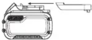
Transport Mode: When the cap is attached to the FLEXVOLT™ battery, the battery is in Transport mode. Keep the cap for shipping.
When in Transport mode, strings of cells are electrically disconnected within the pack resulting in 3 batteries with a
natural_image
Technical line drawing of a mechanical component with no visible text or symbolslower Watt hour (Wh) rating as compared to 1 battery with a higher Watt hour rating. This increased quantity of 3 batteries with the lower Watt hour rating can exempt the pack from certain shipping regulations that are imposed upon the higher Watt hour batteries.
For example, the Transport
Wh rating might indicate 3 x 36 Wh, meaning
3 batteries of 36 Wh each. The Use Wh rating might
indicate 108 Wh (1 battery implied).
Example of Use and Transport Label Marking

Use: 108 Wh

Transport: 3x36 Wh
Storage Recommendations
- The best storage place is one that is cool and dry away from direct sunlight and excess heat or cold. For optimum battery performance and life, store battery packs at room temperature when not in use.
- For long storage, it is recommended to store a fully charged battery pack in a cool, dry place out of the charger for optimal results.
NOTE: Battery packs should not be stored completely depleted of charge. The battery pack will need to be recharged before use.
Labels on Charger and Battery Pack
In addition to the pictographs used in this manual, the labels on the charger and the battery pack may show the following pictographs:

Read instruction manual before use.


See Technical Data for charging time.
Do not probe with conductive objects.
Do not charge damaged battery packs.
Do not expose to water.
Have defective cords replaced immediately
Charge only between 4 °C and 40 °C.
Only for indoor use.

LI-ION
Discard the battery pack with due care for the environment.

Charge DEWALT battery packs only with designated DEWALT chargers. Charging battery packs other than the designated DEWALT batteries with a DEWALT charger may make them burst or lead to other dangerous situations.

Do not incinerate the battery pack.

USE (without transport cap). Example: Wh rating indicates 108 Wh (1 battery with 108 Wh).

TRANSPORT (with built-in transport cap). Example: Wh rating indicates 3 x 36 Wh (3 batteries of 36 Wh).
Battery Type
The following tools operate on a 18 volt battery pack: DCS438, Cat #2.
These battery packs may be used: DCB181, DCB182, DCB183, DCB183B, DCB183G, DCB184, DCB184B, DCB184G, DCB185, DCB187, DCB189, DCB546, DCB547, DCB548, DCBP0304. Refer to
Technical Data for more information.
NOTE: Considering the balance of the tool, the DCB548 battery is not recommended although we have capacity for 60 volt batteries.
Package Contents
The package contains:
1 Cut off tool
2Dustshroud
1Wrench
1 DCBP0304 Battery (E2 model)
1 Li-Ion battery pack (C1, D1, E1, G1, L1, M1, P1, S1, T1, X1, Y1 models)
2 Li-Ion battery packs (C2, D2, E2, G2, L2, M2, P2, S2, T2, X2, Y2 models)
3 Li-lon battery packs (C3, D3, E3, G3, L3, M3, P3, S3, T3, X3, Y3 models)
1 Instructionmanual
NOTE: Battery packs, chargers and kitboxes are not included with N models. Battery packs and chargers are not included with NT models. B models include Bluetooth® battery packs.
NOTE: The Bluetooth® word mark and logos are registered trademarks owned by the Bluetooth®, SIG, Inc. and any use of such marks by DEWALT is under license. Other trademarks and trade names are those of their respective owners.
- Check for damage to the tool, parts or accessories which may have occurred during transport.
• Take the time to thoroughly read and understand this manual prior to operation.
Markings on Tool
The following pictograms are shown on the tool:

Read instruction manual before use.

Wear ear protection.

Wear eye protection.

Visible radiation. Do not stare into light.

Icon order : Reverse/lock/forward
Date Code Position (Fig. B)
The date code 27, which also includes the year of manufacture, is printed into the housing.
Example:
2021 XX XX
Year and Week of Manufacture
Description (Fig. A)
WARNING: Never modify the power tool or any part of it. Damage or personal injury could result.
1 Battery
2 Battery release button
3 Handle
4 Trigger
5 Forward/reverse/lock off button
6 Spindle lock button
7 Direction indicator
8 Dust extraction attachment
9 Dust shoe assembly
10 Depth of cut gauge
11 Depth of cut wing nut
12 Guard
13 Hex wrench
14 Lanyard ready hole
Intended Use
Your cut-off tool is designed for professional cutting applications. This cut-off tool is intended to be used to cut different materials. Follow the information regarding the application range of the cutting blade used.
DO NOT use under wet conditions or in the presence of flammable liquids or gases.
DO NOT let children come into contact with the tool.
Supervision is required when inexperienced operators use this tool.
- Young children and the infirm. This appliance is not intended for use by young children or infirm persons without supervision.
- This product is not intended for use by persons (including children) suffering from diminished physical, sensory or
mental abilities; lack of experience, knowledge or skills unless they are supervised by a person responsible for their safety. Children should never be left alone with this product.
ASSEMBLY AND ADJUSTMENTS
WARNING: To reduce the risk of serious personal injury, turn tool off and disconnect battery pack before making any adjustments or removing/installing attachments or accessories. An accidental start-up can cause injury.
WARNING: Use only DEWALT battery packs and chargers.
Inserting and Removing the Battery Pack from the Tool (Fig. B)
NOTE: Make sure your battery pack 5 is fully charged.
To Install the Battery Pack into the Tool Handle
- Align the battery pack with the rails inside the tool's handle (Fig. B).
- Slide it into the handle until the battery pack is firmly seated in the tool and ensure that you hear the lock snap into place.
To Remove the Battery Pack from the Tool
- Press the battery release button 2 and firmly pull the battery pack out of the tool handle.
- Insert battery pack into the charger as described in the charger section of this manual.
Fuel Gauge Battery Packs (Fig. B)
Some DEWALT battery packs include a fuel gauge which consists of three green LED lights that indicate the level of charge remaining in the battery pack.
To actuate the fuel gauge, press and hold the fuel gauge button 28. A combination of the three green LED lights will illuminate designating the level of charge left. When the level of charge in the battery is below the usable limit, the fuel gauge will not illuminate and the battery will need to be recharged.
NOTE: The fuel gauge is only an indication of the charge left on the battery pack. It does not indicate tool functionality and is subject to variation based on product components, temperature and end-user application.
Wheels
WARNING: To minimize the risk of eye injury, always use eye protection. Carbide is a hard but brittle material. Foreign objects in the workpiece such as wire or nails can cause tips to crack or break. Mount the wheel securely in proper direction of rotation before using, and always use a clean, sharp wheel.
WARNING: To reduce the risk of injury, only use wheels that are no greater than 76 mm in diameter, have an inner diameter of 10 mm, and without cutting teeth. Thickness of wheel not to exceed 0.09".
WARNING: Since accessories, other than those offered by BEWALT, have not been tested with this product, use of such accessories with this tool could be hazardous.
To reduce the risk of injury, only DEWALT recommended accessories should be used with this product.
A dull wheel will cause slow inefficient cutting, overload the motor, could cause excessive splintering, and could increase the possibility of kickback. Please refer to the table below to determine the correct wheel for your application.
| Wheel type Application | |
| Diamond Multi-Material Wheel (DT20590-QZ) | Drywall, fiber cement, plastic, steel, non ferrous materials |
| Bonded Abrasive Wheel (DT20592-QZ) | Steel, stainless steel, non-ferrous materials |
| Diamond Tile Wheel (DT20591-QZ) | Ceramic Tile, Porcelain and Granite/Marble/Stone |
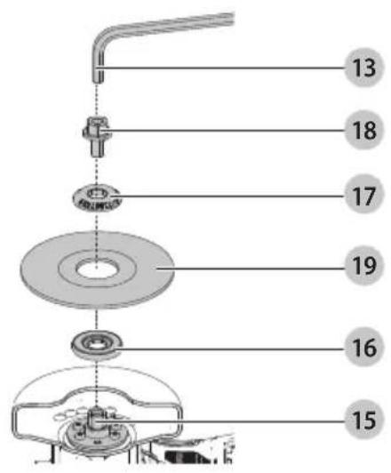
Installing Wheels (Fig. A, C)
WARNING: Burn Hazard. Sharp parts. ALWAYS wear gloves when changing wheels. Wheels have sharp edges or may get extremely hot during operation, and may damage bare hands.
WARNING: To reduce the risk of injury, only use wheels are no greater than 76 mm in diameter, have an inner diameter of 10 mm, and without cutting teeth. Thickness of wheel not to exceed 0.09". Type 1 wheels are for side grinding only, not surface grinding. Never force a wheel onto the machine or alter the size of the arbor hole.
- Remove the battery.
- Lay unit on a firm surface, with the spindle 15 facing upward.
- Hold spindle lock button 6 to keep the spindle from turning. Spindle threads are left hand.
- Using supplied 6 mm wrench 13, remove spindle screw 18, outer flange 17, used wheel 19 if one is installed and inner flange 16. Spindle threads are left hand.
- Slip the inner flange over the spindle.
- Slip wheel over spindle. Make sure wheel goes over pilot diameter of inner flange.
NOTE: When installing diamond wheels, always match direction of rotation of the wheel to the desired direction of rotation of the tool. Diamond wheels will not cut effectively unless the direction marked on the wheel matches the direction of rotation. Check the setting of the forward/reverse/lock off button 5 to make sure it matches the direction marked on the wheel.
- Slip on outer flange with the flat side towards the cut-off wheel.
nOTE: The text "LOOSE TIGHTEN" will be visible when installed correctly.
-
Start threading on spindle screw which will self align outer flange. Make sure the wheel is fitted in the correct orientation.
-
Engage spindle lock button and tighten nut with wrench. Do not over tighten spindle screw.
-
Turn wheel by hand to ensure it is properly centered. The wheel should not hit the shoe, guard or spindle screw. The spindle screw and flanges should be tight.
WARNING: If the spindle screw has not been tightened securely, it can loosen with the F (forward) direction of rotation.
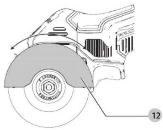
Adjusting the Guard Angle (Fig. D)
WARNING: There is a higher risk of kickback when guard is moved backwards leading to wider opening. The guard must be opened wider only when required.
You can adjust the angle of the guard.
- Remove the battery.
- Grasp the guard 12 firmly and rotate to desired angle. The guard can rotate 30 degrees, forward or backward.
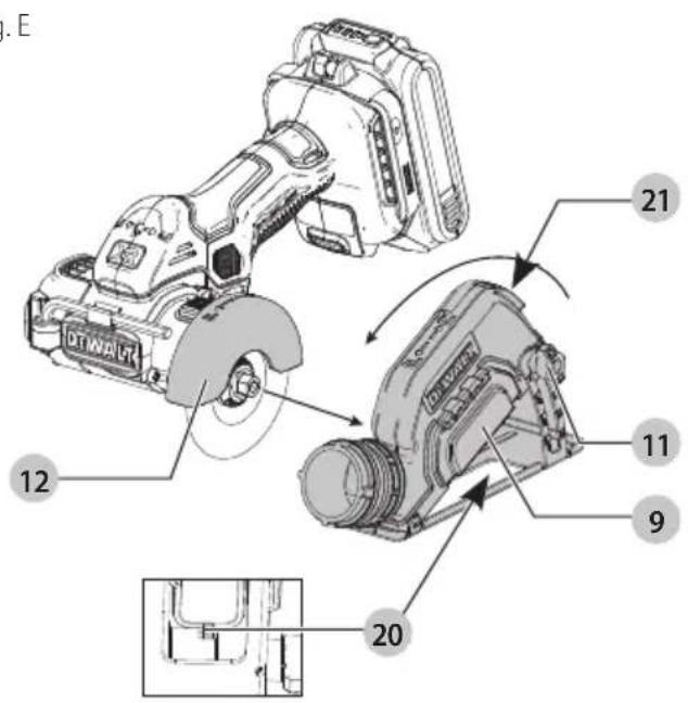
Mounting, Removing and Adjusting the Dust Shroud (Fig. A, E)
NOTE: The dust shroud is only for tile/concrete and drywall cutting applications to connect to a vacuum for dust collecting. We do not recommend use of the shroud for metal cutting applications.
- Remove the battery.
- With the wheel properly installed, rotate the guard 12 all the way forward.
- Loosen the depth of cut wing nut 11 and fully extend the shoe. Hand-tighten the depth of cut knob.
- Maneuver the upper guard and wheel into the dust shroud assembly 9 and rotate tool to lock in place. The front of the guard will rest against the stop inside the assembly, and the back of the guard will catch the release tab 20.
To Remove the Dust Shroud
- Remove the battery.
- Loosen the depth of cut wing nut and fully extend the shoe. Hand-tighten the depth of cut wing nut.
- Press in the shroud release button 21 and rotate the tool out of the dust shroud assembly.
To Adjust the Depth of Cut
- Loosen the depth of cut wing nut and slide the shroud up or down. Use the markings on the depth of cut gauge to help determine proper depth. Adjust the cutting depth to the thickness of the workpiece. Less than 1/4" of the wheel should be visible below the workpiece.
Attaching an AirLock™ Compatible Dust Extractor (Fig. F)
WARNING: Do not use dust extraction when cutting metal. Swarf from metal cutting may be hot and may spark which can melt vacuum hoses and may cause a fire inside the vacuum.
WARNING: When using dust extraction, empty vacuum because the work begins and often during work. Use care in disposing of dust. Dust can be hazardous to health if inhaled, ingested or in contact with the skin. Materials in fine dust can be explosive.
Your tool is compatible with the DEWALT AirLock™ connection system. The AirLock™ allows for a fast, secure connection
between the AirLock™ connector 22 and your tool's dust extraction port 8.
- Remove the battery.
- Ensure the collar on the AirLock™ connector is in the unlock position. (Refer to Figure F.) Align notches 23 on collar and AirLock™ connector as shown for unlock and lock positions.
- Push the AirLock ^™ connector onto the adapter connector point.
- Rotate the collar to the locked position.
NOTE: The ball bearings inside collar lock into slot and secure the connection. The power tool is now securely connected to the dust extractor.
NOTE: The sleeve of the dust extraction port can be removed if damaged and replaced by the user. The sleeve is available as an optional accessory and can be replaced using a screwdriver.
OPERATION
Instructions for Use
WARNING: Always observe the safety instructions and applicable regulations.
WARNING: To reduce the risk of serious personal injury, turn tool off and disconnect battery pack before making any adjustments or removing/installing attachments or accessories. An accidental start-up can cause injury.
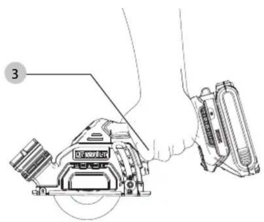
Proper Hand Position (Fig. G)
WARNING: To reduce the risk of serious personal injury, ALWAYS use proper hand position as shown.
WARNING: To reduce the risk of serious personal injury, ALWAYS hold securely in anticipation of a sudden reaction.
WARNING: Keep your free hand far from cutting action. Don't reach underneath the workpiece.
Proper hand position requires one hand on the main handle 3.
Spindle Lock Button (Fig. C, H)
The spindle lock button 6 is used to lock the spindle 15 when changing accessories.
- To engage the spindle lock button, remove the battery pack and make sure trigger switch is in OFF position.
- Depress the spindle lock button and turn the wheel and spindle until the lock button engages the spindle.
- Use supplied wrench 13 to unscrew the spindle nut 18 and remove or mount accessories. Spindle threads are left hand.
Forward/Reverse/Lock Off Button (Fig. A)
Your cut-off tool is equipped with a forward/reverse/lock off button 5. Some applications or accessories may require the tool to be run in forward or reverse. When making a cut, select the direction of cut that allows the tool to be pushed away from your body. When installing a diamond wheel, select the rotation that matches the arrow on the wheel.
- For forward (clockwise) rotation, push the forward/reverse/lock off button all the way to the right, as shown by the direction indicator 7.
- For reverse (counterclockwise) rotation, push the forward/reverse/lock off button all the way to the left, as shown by the direction indicator.
- To lock the trigger switch, push the forward/reverse/lock off button to the centre position, as shown by the direction indicator.
To Operate (Fig. A)
CAUTION: Before attempting to start, grasp tool firmly. WARNING: Edge cutting can be performed only with wheels that are designed and specified for this purpose. Protect yourself during edge cutting by directing the open side of the guard toward a surface. WARNING: Wheels used for cutting may break or kick about if they bend or twist while the tool is being used to do cut-off work. WARNING: Do not use edge cutting wheels for surface grinding applications because these wheels are not designed for side pressures encountered with surface grinding. Wheel breakage and injury may result. WARNING: Do not bang or bump a cut-off wheel when sowing or during a cut.
- Grasp main handle 3 firmly.
- Line up wheel with material to be cut. Be sure nothing is near or in line with the wheel.
- Depress and hold trigger switch 4 then slowly feed wheel into work with firm pressure. Do not force the tool. For maximum efficiency and wheel life, keep the wheel speed high.
- To stop tool, release trigger switch 4.
If Using the Dust Shroud for Dust Collecting (Fig. H)
- Remove battery pack.
- Adjust the depth of cut when using the dust shroud.
- Insert the battery pack.
- While cutting, keep the shoe flat against the workpiece and maintain a firm grip, don't force the cut off tool through the workpiece. Forcing a cut off tool can cause kickback.
NOTE: If making a partial cut, restarting a cut, or correcting cut direction. Allow the wheels to come to a complete stop. To resume cutting, centre the wheel in the kerf (cutting slot) 29, back and saw away from cutting edge, pull the trigger and re-enter the cut slowly. - To stop tool, release trigger switch.
Tool Connect™ Chip (Fig. I)
WARNING: To reduce the risk of serious personal injury, turn unit off and remove the battery pack before making any adjustments or removing/installing attachments or accessories. An accidental start-up can cause injury.
Your tool is Tool Connect™ Chip ready and has a location for installation of a Tool Connect™ Chip.
Tool Connect™ Chip is an optional application for your smart device (such as a smart phone or tablet) that connects the device to utilize the mobile application for inventory management functions.
Refer to Tool Connect™ Chip Instruction Sheet for more information.
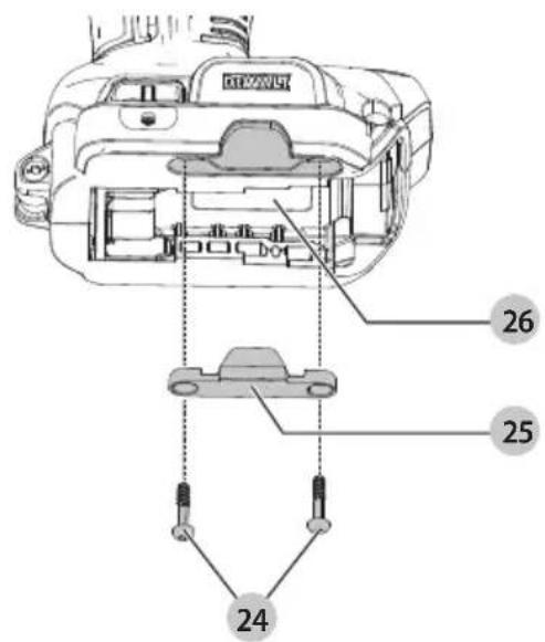
Installing the Tool Connect™ Chip
- Remove the retaining screws 24 that hold the Tool Connect™ Chip protective cover 25 into the tool.
- Remove the protective cover and insert the Tool Connect™ Chip into the empty pocket 26.
- Ensure that the Tool Connect™ Chip is flush with the housing. Secure it with the retaining screws and tighten the screws.
- Refer to Tool Connect™ Chip Instruction Sheet for further instructions.
Transportation and Storage
During transportation and storage lock the trigger switch with the lock-off button.
Remove the battery pack during the tool storage.
MAINTENANCE
Your power tool has been designed to operate over a long period of time with a minimum of maintenance. Continuous satisfactory operation depends upon proper tool care and regular cleaning.
WARNING: To reduce the risk of serious personal injury, turn tool off and disconnect battery pack before making any adjustments or removing/installing attachments or accessories. An accidental start-up can cause injury.
The charger and battery pack are not serviceable.

Lubrication
Your power tool requires no additional lubrication.

Cleaning
WARNING: Blow dirt and dust out of the main housing with dry air as often as dirt is seen collecting in and around the air vents. Wear approved eye protection and approved dust mask when performing this procedure.
WARNING: Never use solvents or other harsh chemicals for cleaning the non-metallic parts of the tool. These chemicals may weaken the materials used in these parts. Use a cloth dampened only with water and mild soap. Never let any liquid get inside the tool; never immerse any part of the tool into a liquid.
Optional Accessories
WARNING: Since accessories, other than those offered by DEWALT, have not been tested with this product, use of such accessories with this tool could be hazardous. To reduce the risk of injury, only DEWALT recommended accessories should be used with this product.
Consult your dealer for further information on the appropriate accessories.
Protecting the Environment
Separate collection. Products and batteries marked with this symbol must not be disposed of with normal household waste.
Products and batteries contain materials that can be recovered or recycled reducing the demand for raw materials. Please recycle electrical products and batteries according to local provisions. Further information is available at www.2helpU.com.
Rechargeable Battery Pack
This long life battery pack must be recharged when it fails to produce sufficient power on jobs which were easily done before. At the end of its technical life, discard it with due care for our environment:
- Run the battery pack down completely, then remove it from the tool.
- Li-lon cells are recyclable. Take them to your dealer or a local recycling station. The collected battery packs will be recycled or disposed of properly.
natural_image
Technical line drawing of a mechanical component with no visible text or symbolsnatural_image
Technical line drawing of a mechanical component or housing assembly (no text or symbols visible)Bloc-batterie rechargeable
natural_image
Technical line drawing of a mechanical component with no visible text or symbolsBEWAAR ALLE WAARSCHUWINGEN EN INSTRUCTIES ALS TOEKOMSTIG REFERENTIEMATERIAAL
VEILIGHEIDSWAARSCHUWINGEN VOOR AFKORTZAAGMACHINES
VEILIGHEIDSWAARSCHUWINGEN VOOR SLIJP-EN AFKORTBEWERKINGEN
natural_image
Technical line drawing of a mechanical component with no visible text or symbols3 Li-lon-accu's (modellen C3, D3, E3, G3, L3, M3, P3, S3, T3, X3, Y3)
text_image
Mr. GeorgolMarkus Rompel
Vice-President Engineering, PTE-Europe
DEWALT, Richard-Klinger-Straße 11, 65510, Idstein, Tyskland
24.09.2021

ADVARSEL: For å redusere skaderisikoen, les bruksanvisningen.