
DCG400 - Grinder DEWALT - Free user manual and instructions
Find the device manual for free DCG400 DEWALT in PDF.

| Product Type | Cordless Angle Grinder (Small) |
| Brand | DeWALT |
| Model | DCG400 |
| Power Source | 20V MAX* Lithium-Ion Battery Pack |
| Switch Type | Paddle Switch with Lock-Off Lever |
| Max Wheel Diameter | 4 in (100 mm) |
| Arbor Thread | 5/8 in - 11 (Universal) |
| No Load Speed | Not specified (estimated 15,000 RPM) |
| Weight (without battery pack) | Approximately 1.5 kg |
| Dimensions (L × W × H) | Approximately 300 × 100 × 100 mm |
| Guard Included | Type B Guard (for grinding) + Type A Clip-on Guard (for cutting) |
| Main Functions | Grinding, sanding, wire brushing, cutting off |
| Safety Features | E-Switch Protection (restart after power interruption), anti-rotation system, Power-Off overload protection, soft start |
| Lanyard Attachment Point | Yes (optional accessory) |
| Maintenance and Cleaning | Blow out vents with dry air once a week; clean with a damp cloth (water and mild soap) |
| Spare Parts and Repairability | Repairs by authorized service center only; use identical DeWalt parts |
| Warranty | 3-year limited |
| Prohibited Applications | Do not use for wood, toothed blades, polishing (not recommended) |
Frequently Asked Questions - DCG400 DEWALT
User questions about DCG400 DEWALT
0 question about this device. Answer the ones you know or ask your own.
Ask a new question about this device
Download the instructions for your Grinder in PDF format for free! Find your manual DCG400 - DEWALT and take your electronic device back in hand. On this page are published all the documents necessary for the use of your device. DCG400 by DEWALT.
USER MANUAL DCG400 DEWALT
natural_image
Technical line drawings of a DeWalt industrial grinding machine (no text or symbols present)
WARNING: Read all safety warnings, instructions, illustrations, and specifications in this manual, including the battery and
charger sections provided in an original tool manual or the separate Batteries and Chargers manual.
Manuals can be obtained by contacting Customer Service as described elsewhere in this manual. Failure to follow the warnings and instructions may result in electric shock, fire and/or serious injury.

English (original instructions) 6
| Français (traduction de la notice d'instructions originale) | 19 |
| Español (traducido de las instrucciones originales) | 33 |
1 Paddle switch
2 Lock-off lever
3 Spindle lock button
4 Spindle
5 Side handle (DCG402)
6 3/8" & 5/8" arbor reversible backing flange (DCG400)
7 3/8" arbor locking flange (DCG400)
8 5/8" arbor locking flange (DCG400)
9 Backing flange (DCG402)
10 Locking flange (DCG402)
11 Type B guard
12 Type A Clip-on guard
13 Guard release lever
14 Battery pack
15 Battery release button
16 DCG400 wrench
17 DCG402 wrench
18 Threaded flange holder
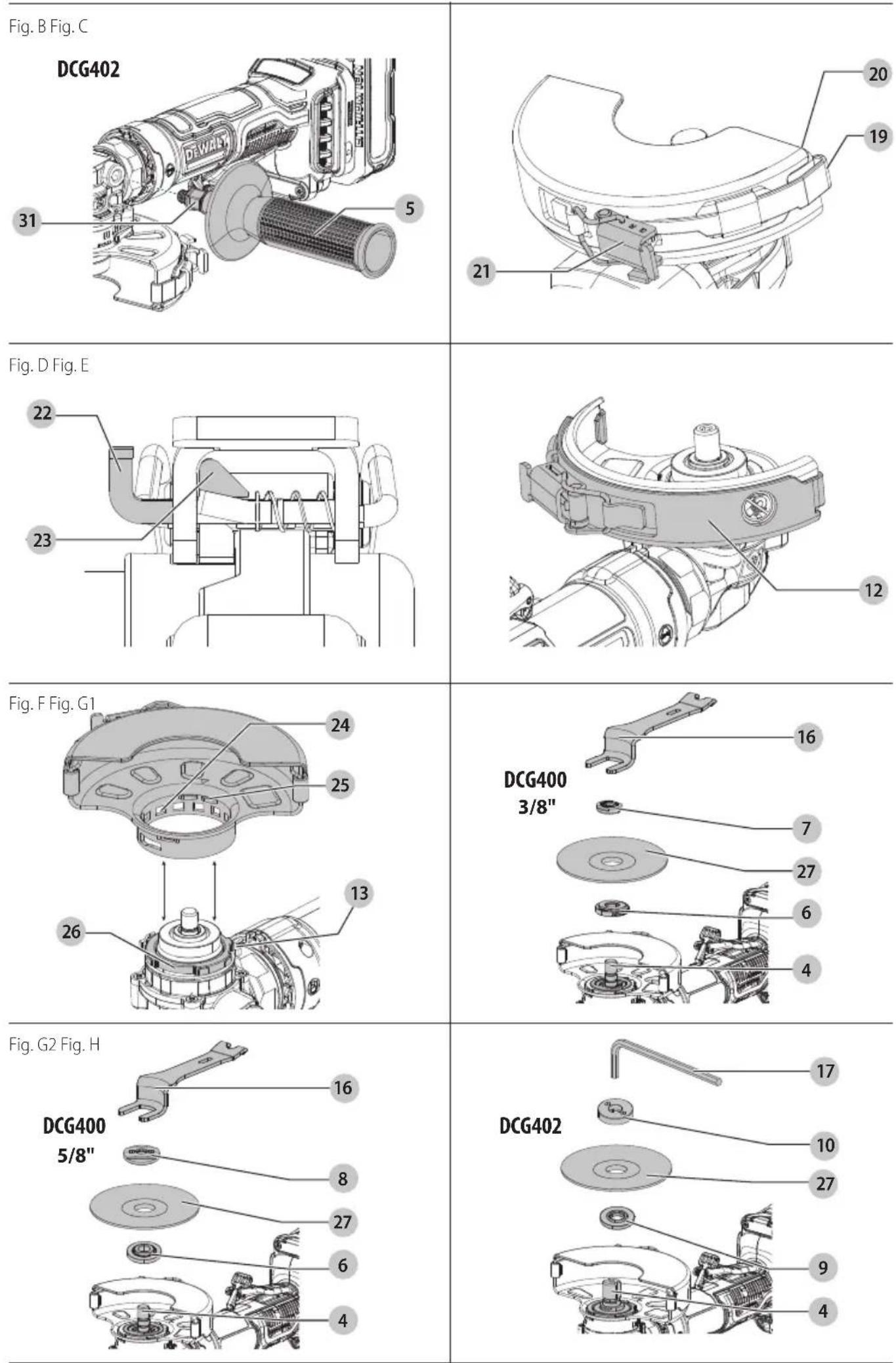
Fig. I Fig. J
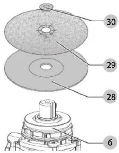
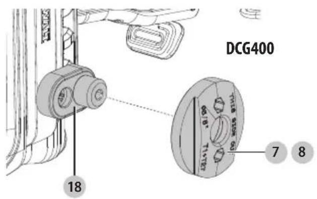
Fig. K Fig. L
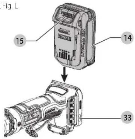
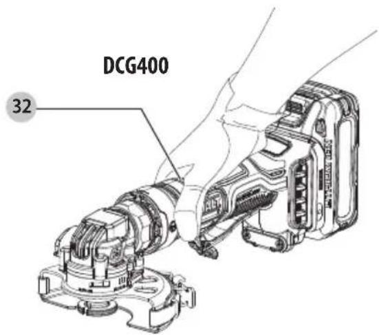
Fig. M
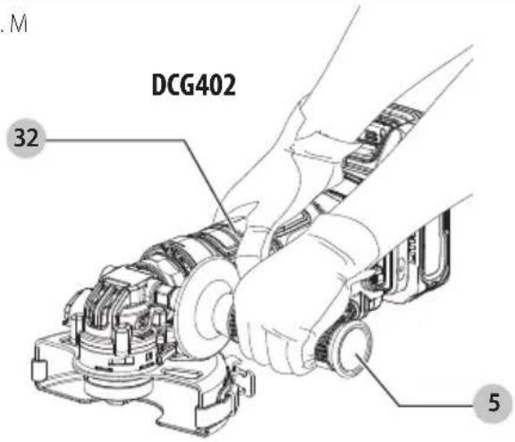
Fig. N
natural_image
Technical line drawing of a mechanical component with no visible text or symbolsFig. O Fig. P
natural_image
Technical line drawing of a mechanical component with an arrow indicating direction (no text or symbols)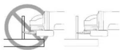
natural_image
Two technical diagrams showing a no-smoking symbol and a mechanical assembly (no text or labels)English
Intended Use
Your heavy-duty small angle grinder has been designed for professional grinding, sanding, wire brush, and cut-off applications at various work sites (i.e., construction sites).
DO nOT use under wet conditions or in presence of flammable liquids or gases.
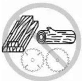
RANGER: Do not use for wood cutting or woodcarving.
Do not use toothed blades of any kind. Serious injury can result.
Your heavy-duty small angle grinder is a professional power tool. DO nOT let children come into contact with the tool. Supervision is required when inexperienced operators use this tool.
Definitions: Safety Alert Symbols and Words
This instruction manual uses the following safety alert symbols and words to alert you to hazardous situations and your risk of personal injury or property damage.
RANGER: Indicates an imminently hazardous situation which, if not avoided, will result in death or serious injury.
WARNING: Indicates a potentially hazardous situation which, if not avoided, could result in death or serious injury.
AUTION: Indicates a potentially hazardous situation which, if not avoided, may result in minor or moderate injury.
(Used without word) Indicates a safety related message. NOTICE: Indicates a practice not related to personal injury which, if not avoided, may result in property damage.
GENERAL POWER TOOL SAFETY WARNINGS
WARNING: Read all safety warnings, instructions, illustrations and specifications provided with this power tool. Failure to follow all instructions listed below may result in electric shock, fire and/or serious injury.
SAVE ALL WARNINGS AND INSTRUCTIONS FOR FUTURE REFERENCE.
The term "power tool" in the warnings refers to your mains-operated (corded) power tool or battery-operated (cordless) power tool.
1) Work Area Safety
a) Keep work area clean and well lit. Cluttered or dark areas invite accidents.
b) Do not operate power tools in explosive atmospheres, such as in the presence of flammable liquids, gases or dust. Power tools create sparks which may ignite the dust or fumes.
c) Keep children and bystanders away while operating a power tool. Distractions can cause you to lose control.
2) Electrical Safety
a) Power tool plugs must match the outlet. Never modify the plug in any way. Do not use any adapter plugs with earthed (grounded) power tools. Unmodified plugs and matching outlets will reduce risk of electric shock.
b) Avoid body contact with earthed or grounded surfaces, such as pipes, radiators, ranges and refrigerators. There is an increased risk of electric shock if your body is earthed or grounded.
c) Do not expose power tools to rain or wet conditions. Water entering a power tool will increase the risk of electric shock.
d) Do not abuse the cord. Never use the cord for carrying, pulling or unplugging the power tool. Keep cord away from heat, oil, sharp edges or moving parts. Damaged or entangled cords increase the risk of electric shock.
e) When operating a power tool outdoors, use an extension cord suitable for outdoor use. Use of a cord suitable for outdoor use reduces the risk of electric shock.
f) If operating a power tool in a damp location is unavoidable, use a ground fault circuit interrupter (GFCI) protected supply. Use of a GFCI reduces the risk of electric shock.
3) Personal Safety
a) Stay alert, watch what you are doing and use common sense when operating a power tool. Do not use a power tool while you are tired or under the influence of drugs, alcohol or medication. A moment of inattention while operating power tools may result in serious personal injury.
b) Use personal protective equipment. Always wear eye protection. Protective equipment such as a dust mask, non-skid safety shoes, hard hat, or hearing protection used for appropriate conditions will reduce personal injuries.
c) Prevent unintentional starting. Ensure the switch is in the off position before connecting to power source and/or battery pack, picking up or carrying the tool. Carrying power tools with your finger on the switch or energizing power tools that have the switch on invites accidents.
d) Remove any adjusting key or wrench before turning the power tool on. A wrench or a key left attached to a rotating part of the power tool may result in personal injury.
e) Do not overreach. Keep proper footing and balance at all times. This enables better control of the power tool in unexpected situations.
f) Dress properly. Do not wear loose clothing or jewelry. Keep your hair, clothing and gloves away from moving parts. Loose clothes, jewelry or long hair can be caught in moving parts.
g) If devices are provided for the connection of dust extraction and collection facilities, ensure these are connected and properly used. Use of dust collection can reduce dust-related hazards.
h) Do not let familiarity gained from frequent use of tools allow you to become complacent and ignore tool safety principles. A careless action can cause severe injury within a fraction of a second.
4) Power Tool Use and Care
a) Do not force the power tool. Use the correct power tool for your application. The correct power tool will do the job better and safer at the rate for which it was designed.
b) Do not use the power tool if the switch does not turn it on and off. Any power tool that cannot be controlled with the switch is dangerous and must be repaired.
c) Disconnect the plug from the power source and/or remove the battery pack, if detachable, from the power tool before making any adjustments, changing
accessories, or storing power tools. Such preventive safety measures reduce the risk of starting the power tool accidentally.
d) Store idle power tools out of the reach of children and do not allow persons unfamiliar with the power tool or these instructions to operate the power tool. Power tools are dangerous in the hands of untrained users.
e) Maintain power tools and accessories. Check for misalignment or binding of moving parts, breakage of parts and any other condition that may affect the power tool's operation. If damaged, have the power tool repaired before use. Many accidents are caused by poorly maintained power tools.
f) Keep cutting tools sharp and clean. Properly maintained cutting tools with sharp cutting edges are less likely to bind and are easier to control.
g) Use the power tool, accessories and tool bits, etc. in accordance with these instructions, taking into account the working conditions and the work to be performed.
Use of the power tool for operations different from those intended could result in a hazardous situation.
h) Keep handles and grasping surfaces dry, clean and free from oil and grease. Slippery handles and grasping surfaces do not allow for safe handling and control of the tool in unexpected situations.
5) Battery Tool Use and Care
a) Recharge only with the charger specified by the manufacturer. A charger that is suitable for one type of battery pack may create a risk of fire when used with another battery pack.
b) Use power tools only with specifically designated battery packs. Use of any other battery packs may create a risk of injury and fire.
c) When battery pack is not in use, keep it away from other metal objects, like paper clips, coins, keys, nails, screws or other small metal objects, that can make a connection from one terminal to another. Shorting the battery terminals together may cause burns or a fire.
d) Under abusive conditions, liquid may be ejected from the battery; avoid contact. If contact accidentally occurs, flush with water. If liquid contacts eyes, additionally seek medical help. Liquid ejected from the battery may cause irritation or burns.
e) Do not use a battery pack or tool that is damaged or modified. Damaged or modified batteries may exhibit unpredictable behavior resulting in fire, explosion or risk of injury.
f) Do not expose a battery pack or tool to fire or excessive temperature. Exposure to fire or temperature above 265 °F (130 °C) may cause explosion.
g) Follow all charging instructions and do not charge the battery pack or tool outside the temperature range specified in the instructions. Charging improperly or at temperatures outside the specified range may damage the battery and increase the risk of fire.
6) Service
a) Have your power tool serviced by a qualified repair person using only identical replacement parts. This will ensure that the safety of the power tool is maintained.
b) Never service damaged battery packs. Service of battery packs should only be performed by the manufacturer or authorized service providers.
SAFETY INSTRUCTIONS FOR ALL OPERATIONS Safety Warnings Common for Grinding, Sanding, Wire Brushing or Abrasive Cutting-Off Operations
a) This power tool is intended to function as a grinder, sander, wire brush or cut-off tool. Read all safety warnings, instructions, illustrations and specifications provided with this power tool. Failure to follow all instructions listed below may result in electric shock, fire and/or serious injury.
b) Operations such as polishing are not recommended to be performed with this power tool. Operations for which the power tool was not designed may create a hazard and cause personal injury.
c) Do not convert this power tool to operate in a way which is not specifically designed and specified by the tool manufacturer. Such a conversion may result in a loss of control and cause serious personal injury.
d) Do not use accessories which are not specifically designed and recommended by the tool manufacturer. Just because the accessory can be attached to your power tool, it does not assure safe operation.
e) The rated speed of the accessory must be at least equal to the maximum speed marked on the power tool. Accessories running faster than their rated speed can break and fly apart.
f) The outside diameter and the thickness of your accessory must be within the capacity rating of your power tool. Incorrectly sized accessories cannot be adequately guarded or controlled.
g) Threaded mounting of accessories must match the grinder spindle thread. For accessories mounted by flanges, the arbor hole of the accessory must fit the locating diameter of the flange. Accessories that do not match the mounting hardware of the power tool will run out of balance, vibrate excessively and may cause loss of control.
h) The dimensions of the accessory mounting must fit the dimensions of the mounting hardware of the power tool. Accessories that do not match the mounting hardware of the power tool will run out of balance, vibrate excessively and may cause loss of control.
i) Do not use a damaged accessory. Before each use inspect the accessory such as abrasive wheels for chips and cracks, backing pad for cracks, tear or excess wear, wire brush for loose or cracked wires. If power tool or accessory is dropped, inspect for damage or install an undamaged accessory. After inspecting and installing an accessory, position yourself and bystanders away from the plane of the rotating accessory and run the power tool at maximum no-load speed for one minute. Damaged accessories will normally break apart during this test time.
j) Wear personal protective equipment. Depending on application, use face shield, safety goggles or safety glasses. As appropriate, wear dust mask, hearing protectors, gloves and workshop apron capable of stopping small abrasive or workpiece fragments. The
English
eye protection must be capable of stopping flying debris generated by various operations. The dust mask or respirator must be capable of filtrating particles generated by your operation. Prolonged exposure to high intensity noise may cause hearing loss.
k) Keep bystanders a safe distance away from work area. Anyone entering the work area must wear personal protective equipment. Fragments of workpiece or of a broken accessory may fly away and cause injury beyond immediate area of operation.
1) Hold the power tool by insulated gripping surfaces only, when performing an operation where the cutting tool may contact hidden wiring. Contact with a "live" wire will also make exposed metal parts of the power tool "live" and could give the operator an electric shock.
m) Never lay the power tool down until the accessory has come to a complete stop. The spinning accessory may grab the surface and pull the power tool out of your control.
n) Do not run the power tool while carrying it at your side. Accidental contact with the spinning accessory could snag your clothing, pulling the accessory into your body.
o) Regularly clean the power tool's air vents. The motor's fan will draw the dust inside the housing and excessive accumulation of powdered metal may cause electrical hazards.
p) Do not operate the power tool near flammable materials. Sparks could ignite these materials.
q) Do not use accessories that require liquid coolants. Using water or other liquid coolants may result in electrocution or shock.
r) Do not use Type 11 (flaring cup) wheels on this tool. Using inappropriate accessories can result in injury.
s) Always use side handle. Tighten the handle securely. The side handle should always be used to maintain control of the tool at all times.
t) When starting the tool with a new or replacement wheel, or a new or replacement wire brush installed, hold the tool in a well protected area and let it run for one minute. If the wheel has an undetected crack or flaw, it should burst in less than one minute. If the wire brush has loose wires, they will be detected. Never start the tool with a person in line with the wheel. This includes the operator.
u) Use of accessories not specified in this manual is not recommended and may be hazardous. Use of power boosters that would cause the tool to be driven at speeds greater than its rated speed constitutes misuse.
v) Use clamps or another practical way to secure and support the workpiece to a stable platform. Holding the work by hand or against your body leaves it unstable and may lead to loss of control.
w) Avoid bouncing the wheel or giving it rough treatment. If this occurs, stop the tool and inspect the wheel for cracks or flaws.
x) Always handle and store wheels in a careful manner.
y) Do not operate this tool for long periods of time. Vibration caused by the operating action of this tool may cause permanent injury to fingers, hands, and arms. Use gloves to provide extra cushion, take frequent rest periods, and limit daily time of use.
z) Air vents often cover moving parts and should be avoided. Loose clothes, jewelry or long hair can be caught in moving parts.
Kickback and Related Warnings
Kickback is a sudden reaction to a pinched or snagged rotating wheel, backing pad, brush or any other accessory. Pinching or snagging causes rapid stalling of the rotating accessory which in turn causes the uncontrolled power tool to be forced in the direction opposite of the accessory's rotation at the point of the binding.
For example, if an abrasive wheel is snagged or pinched by the workpiece, the edge of the wheel that is entering into the pinch point can dig into the surface of the material causing the wheel to climb out or kick out. The wheel may either jump toward or away from the operator, depending on direction of the wheel's movement at the point of pinching. Abrasive wheels may also break under these conditions.
Kickback is the result of tool misuse and/or incorrect operating procedures or conditions and can be avoided by taking proper precautions as given below:
a) Maintain a firm grip on the power tool and position your body and arm to allow you to resist kickback forces. Always use auxiliary handle, if provided, for maximum control over kickback or torque reaction during start up. The operator can control torque reaction or kickback forces, if proper precautions are taken.
b) Never place your hand near the rotating accessory. Accessory may kickback over your hand.
c) Do not position your body in the area where power tool will move if kickback occurs. Kickback will propel the tool in direction opposite to the wheel's movement at the point of snagging.
d) Use special care when working corners, sharp edges etc. Avoid bouncing and snagging the accessory. Corners, sharp edges or bouncing have a tendency to snag the rotating accessory and cause loss of control or kickback.
e) Do not attach a saw chain woodcarving blade or toothed saw blade. Such blades create frequent kickback and loss of control.
Safety Warnings Specific for Grinding and Abrasive Cutting-Off Operations
a) Use only wheel types that are recommended for your power tool and the specific guard designed for the selected wheel. Wheels for which the power tool was not designed cannot be adequately guarded and are unsafe.
b) The grinding surface of center depressed wheels must be mounted below the plane of the guard lip. An improperly mounted wheel that projects through the plane of the guard lip cannot be adequately protected.
c) The guard must be securely attached to the power tool and positioned for maximum safety, so the least amount of wheel is exposed towards the operator.
The guard helps to protect the operator from broken wheel fragments, accidental contact with wheel and sparks that could ignite clothing.
d) Wheels must be used only for recommended applications. For example: do not grind with the side of cut-off wheel. Abrasive cut-off wheels are intended for peripheral grinding, side forces applied to these wheels may cause them to shatter.
e) Always use undamaged wheel flanges that are of correct size and shape for your selected wheel. Proper wheel flanges support the wheel thus reducing the
possibility of wheel breakage. Flanges for cut-off wheels may be different from grinding wheel flanges.
f) Do not use worn down wheels from larger power tools. Wheel intended for larger power tool is not suitable for the higher speed of a smaller tool and may burst.
g) When using dual purpose wheels always use the correct guard for the application being performed. Failure to use the correct guard may not provide the desired level of guarding, which could lead to serious injury.
Additional Safety Warnings Specific for Abrasive Cutting-Off Operations
a) Do not "jam" the cut-off wheel or apply excessive pressure. Do not attempt to make an excessive depth of cut. Overstressing the wheel increases the loading and susceptibility to twisting or binding of the wheel in the cut and the possibility of kickback or wheel breakage.
b) Do not position your body in line with and behind the rotating wheel. When the wheel, at the point of operation, is moving away from your body, the possible kickback may propel the spinning wheel and the power tool directly at you.
c) When wheel is binding or when interrupting a cut for any reason, switch off the power tool and hold the power tool motionless until the wheel comes to complete stop. Never attempt to remove the cut-off wheel from the cut while the wheel is in motion otherwise kickback may occur. Investigate and take corrective action to eliminate the cause of wheel binding.
d) Do not restart the cutting operation in the workpiece. Let the wheel reach full speed and carefully reenter the cut. The wheel may bind, walk up or kickback if the power tool is restarted in the workpiece.
e) Support panels or any oversized workpiece to minimize the risk of wheel pinching and kickback. Large workpieces tend to sag under their own weight. Supports must be placed under the workpiece near the line of cut and near the edge of the workpiece on both sides of the wheel.
f) Use extra caution when making a "pocket cut" into existing walls or other blind areas. The protruding wheel may cut gas or water pipes, electrical wiring or objects that can cause kickback.
g) Do not attempt to do curved cutting. Overstressing the wheel increases the loading and susceptibility to twisting or binding of the wheel in the cut and the possibility of kickback or wheel breakage, which can lead to serious injury.
Safety Warnings Specific for Sanding Operations
a) Do not use excessively oversized sanding disc paper. Follow manufacturer's recommendations when selecting sanding paper. Larger sanding paper extending beyond the sanding pad presents a laceration hazard and may cause snagging, tearing of the disc or kickback.
Safety Warnings Specific for Wire Brushing Operations
a) Be aware that wire bristles are thrown by the brush even during ordinary operation. Do not overstress the wires by applying excessive load to the brush. The wire bristles can easily penetrate light clothing and/or skin.
b) Guard must be used for wire brushing, do not allow any interference of the wire wheel or brush with the guard. Wire wheel or brush may expand in diameter due to work and centrifugal forces.
c) Safety goggles or safety glasses with side shields and a full face shield compliant with ANSI Z87.1 MUST be worn by the operator and others that are within 50' (15.2 m) of the use of this product.
Additional Safety Information
WARNING: Never modify the power tool or any part of it. Damage or personal injury could result.
WARNING: ALWAYS use safety glasses. Everyday eyeglasses are NOT safety glasses. Also use face or dust mask if cutting operation is dusty. ALWAYS WEAR CERTIFIED SAFETY EQUIPMENT:
• ANSI Z87.1 eye protection (CAN/CSA Z94.3),
• ANSI S12.6 (S3.19) hearing protection,
• NIOSH/OSHA/MSHA respiratory protection.
WARNING: Some dust created by power sanding, sawing, grinding, drilling, and other construction activities contains chemicals known to the State of California to cause cancer, birth defects or other reproductive harm. Some examples of these chemicals are:
- lead from lead-based paints,
• crystalline silica from bricks and cement and other masonry products, and
• arsenic and chromium from chemically-treated lumber.
Your risk from these exposures varies, depending on how often you do this type of work. To reduce your exposure to these chemicals: work in a well ventilated area, and work with approved safety equipment, such as those dust masks that are specially designed to filter out microscopic particles.
- Avoid prolonged contact with dust from power sanding, sawing, grinding, drilling, and other construction activities. Wear protective clothing and wash exposed areas with soap and water. Allowing dust to get into your mouth, eyes, or lay on the skin may promote absorption of harmful chemicals.
WARNING: Use of this tool can generate and/or disperse dust, which may cause serious and permanent respiratory or other injury. Always use NIOSH/OSHA approved respiratory protection appropriate for the dust exposure. Direct particles away from face and body.
WARNING: Always wear proper personal hearing protection that conforms to ANSI S12.6 (S3.19) during use. Under some conditions and duration of use, noise from this product may contribute to hearing loss.
▲AUTION: When not in use, place tool on its side on a stable surface where it will not cause a tripping or falling hazard. Some tools with large battery packs will stand upright on the battery pack but may be easily knocked over.
The label on your tool may include the following symbols. The symbols and their definitions are as follows:
| V......volts | sfpm......surface feet per minute |
| Hz......hertz | |
| min......minutes | SPM......strokes per minute |
| ——or DC......direct current | A......amperes |
| Class I Construction | W......watts |
| (grounded) | ~ or AC......alternating current |
| .../min......per minute | or AC/DC....alternatingor |
| BPM......beats per minute | direct current |
| IPM....impacts per minute | ClassII |
| RPM....revolutionsper minute | Construction (double insulated) |
ENGLISH
n_0 .....no load speed n .....rated speed

.earthing terminal
⚠️ ......safety alert symbol
▲......visible radiation
......wearrespiratory protection

.weareye
protection

wearhearing
protection

readall
documentation
Lanyard Connection (Fig. K)
Optional Accessory
Safety Warnings Specific for Use At Height
WARNING:
- If the tool is dropped for any reason the lanyard connection must be inspected and properly serviced prior to reuse. The lanyard connection is designed to stretch to absorb the shock of a drop. Any permanent stretch to the connection exposing the red marked internal coils indicates it has been compromised and must be serviced prior to reuse.
- Do not use hang hook as lanyard attachment point.
- Only use batteries that contain the integral battery strap. Do not use unsecured batteries while the tool is tethered. Unsecured batteries may detach from the tool if dropped.
• Always keep the tool and accessories tethered when working "at height". (Maximum lanyard length: 6.5 ft [2 m].)
- Use only with lanyards appropriate for this tool type and rated for at least the weight identified on the tool lanyard attachment point label.
- Crush, cut or entanglement hazard. Do not use near moving parts, mechanisms or running machinery.
- Do not anchor the tool lanyard to anything on your body. Anchor to a rigid structure that can withstand the forces of a dropped tool.
- Make sure the lanyard is properly secure at each end prior to use.
- Inspect tool and lanyard before each use for damage and proper function (including fabric and stitching). Do not use if damaged or not functioning properly.
- Do not alter the lanyard attachment point or use in a manner other than as instructed in this manual.
- Only attach tool to a lanyard with a locking carabiner. Do not attach by looping or knotting the lanyard. Do not use rope or cord.
- Electrical shock hazard. Be sure power is off when working in high voltage areas. Some lanyards are conductive.
- Dropped tools will swing on the lanyard, which could cause injury or loss of balance.
- Do not carry the tool by the attachment point, the battery strap or the lanyard.
- Do not attach more than one tool to each lanyard.
- Only use appropriate DEWALT brand lanyard-ready attachment kit. NEVER modify tools to create attachment points.
- Only transfer the tool between hands while properly balanced in a stable orientation.
- Do not attach lanyards to tool in a way that keeps guards, switches or lock-offs from operating properly.
- Avoid getting tangled in the lanyard.
- Keep lanyard away from the cutting area of the tool.
- Do not use lanyards or attachment devices to get additional leverage from the tool.
- Do not use for personal fall protection.
- Falling object hazard! Only change batteries, accessories and attachments where a dropped object won't cause a hazard below you. Consult your Authority Having Jurisdiction (AHJ) or site supervisor for procedures for working at height.
- Do not use the charger or contractor bag at height.
- Use multi-action or screw gate type carabiners. Do not use single action spring clip carabiners.
The bracket 33 is for mounting the DEWALT Lanyard Ready Attachment Point, available at a DEWALT service center.
The lanyard-ready attachment kit is intended for use by competent personnel who are trained and knowledgeable regarding working with tools in and around machinery and "at height". A lanyard-ready attachment kit may only be added to certain models and must be installed by an authorized service center.
Features
E-Switch Protection™
The ON/OFF paddle switch has a no-volt release function. In the event of an unexpected shut down, the paddle switch will need to be released then depressed to restart tool.
DEWALT ANTI-ROTATION System
This feature quickly stops the accessory when a pinch, stall, or bind-up event is sensed, reducing reactionary torque. The switch needs to be cycled (turned on and off) to restart the tool.
Power-OFF™ Overload Protection
The power supply to the motor will be reduced in case of motor overload. With continued motor overload, the tool will shut off. The paddle switch will need to be released then depressed to restart tool. The tool will power off each time the current load reaches the overload current value (motor burn-up point). If continued overload shutdowns occur, apply less force/weight on the tool until the tool will function without the overload engaging.
Electronic Soft Start
This feature limits the initial start-up momentum, allowing the speed to build up gradually over a 1 second period.
ASSEMBLY AND ADJUSTMENT
WARNING: To reduce the risk of serious personal injury, turn unit off and remove the battery pack before making any adjustments or removing/installing attachments or accessories. An accidental start-up can cause injury.
Attaching Side Handle (Fig. B)
DCG402
WARNING: Side handle must be used on DCG402 at all times to maintain control of the tool.
WARNING: Before using the tool, check that the handle is tightened securely.
Screw the side handle extension piece 31 tightly into one of the holes on either side of the gear case. The side handle 5 should always be used to maintain control of the tool at all times.
Guards
CAUTION: Guards must be used with all grinding wheels, cutting wheels, sanding flap discs, wire brushes, and wire wheels. The tool may be used without a guard only when sanding with conventional sanding discs. Refer to the Accessories Chart to see guards provided with the unit.
Some applications may require purchasing the correct guard from your local dealer or authorized service center.
NOTE: Edge grinding and cutting can be performed with 4" (100 mm) Type 27 wheels designed and specified for this purpose; 1/4" (6.35 mm) thick wheels are designed for surface grinding while thinner 1/8" (3.1 mm) Type 27 wheels need to be examined for the manufacturer's label to see if they can be used for surface grinding or only edge grinding/cutting. A Type B guard with assembled Type A Clip-On guard must be used for any wheel where surface grinding is forbidden. Cutting can also be performed by using a Type B guard with assembled Type A Clip-On guard. 1/4" (6.35 mm) wire wheels with a 5/8" maximum thickness can be used with Type B guard.
NOTE: Refer to the Accessories Chart to select the proper guard/accessory combination.
Mounting the Clip-on Guard (Fig. A, C–E)
WARNING: The Type A Clip-On guard must be assembled to the Type B Guard for all cutting operations. The Type A Clip-on guard converts a Type B guard into a Type A guard.
- Place the Type A Clip-on guard onto the Type B guard so the hook 19 on the end of the Type A Clip-on guard aligns with the edge 20 of the Type B guard.
- Press down on the Type A Clip-on guard lever 21 until the lock button 22 engages with the locking hook 23. The Type A Clip-on guard is now locked in place.
- To remove the Type A Clip-on guard, press the lock button 22 toward the Type A Clip-on guard lever and the Type A Clip-on lever will release. The Type A Clip-on lever can now be lifted, and the Type A Clip-on guard can be removed from the Type B guard.
NOTE: The Type A Clip on guard can be stored on the back of the guard such that the NO CUTTING icon can be seen through the opening in the Type A Clip on guard (Fig. E).
Adjusting and Mounting Guard (Fig. F)
WARNING: To reduce the risk of serious personal injury, turn tool off and disconnect battery pack before making any adjustments or removing/installing attachments or accessories. An accidental start-up can cause injury.
CAUTION: BEFORE operating the tool, identify which guard adjustment option your tool is set to.
Adjustment Options
For guard adjustment, press the guard release lever 13 and adjust the guard until it engages one of the alignment holes 24 on the guard collar.
Mounting Guard
CAUTION: Prior to mounting guard, ensure the screw, lever, and spring of release lever are fitted correctly before mounting the guard.
- With the spindle facing the operator, press and hold the guard release lever 13.
- Align the lugs 25 on the guard with the slots 26 on the gear case cover.
- Push the guard down until the guard lugs engage and rotate them in the groove on the gear case cover. Release the guard release lever.
- To position the guard, rotate the guard clockwise into the desired working position. Press and hold the
guard release lever 13 to rotate the guard in the counter-clockwise direction.
NOTE: The guard body should be positioned between the spindle and the operator to provide maximum operator protection. The guard release lever should snap into one of the alignment holes 24 on the guard collar. This ensures that the guard is secure.
- To remove the guard, follow steps 1–3 of these instructions in reverse.
Flanges and Wheels
▲AUTION: Turn unit off and remove battery from the tool before making any adjustments or removing or installing attachments or accessories.
Mounting Non-Hubbed Wheels (Fig. G1, G2, H)
WARNING: Failure to properly seat the flanges and/or wheel could result in serious injury (or damage to the tool or wheel).
▲AUTION: Included flanges must be used with depressed center Type 27/42 grinding wheels and Type 1/41 cutting wheels. Refer to the Accessories Chart for more information.
WARNING: A closed, two-sided cutting wheel guard (utilizing the Type A Clip-On guard) is required when using abrasive cutting wheels or diamond-coated cutting wheels (Type A Clip-On guard must be assembled over the wheel).
WARNING: To prevent wheel from coming off, always fully tighten the locking flange with provided wrench.
WARNING: Use of a damaged flange or guard or failure to use proper flange and guard can re sult in injury due to wheel breakage and wheel contact. Refer to the Accessories Chart for more information.
DCG400 (Fig. G1, G2)
- Place the tool on a table, guard up.
- Install the reversible backing flange 6 on spindle 4 with the appropriate side facing up for either 5/8" arbor or 3/8" arbor accessories. Press the backing flange into place, ensuring it is fully seated. When fully seated, the backing flange should not be able to rotate independently of the spindle.
- Place wheel 27 against the backing flange.
a. For 3/8" arbor accessories, Ensure the backing flange side labeled "3/8" is facing out. Place wheel against the backing flange, centering the wheel directly on the spindle (Fig. G1).
b. For 5/8" arbor accessories, Ensure the backing flange side labeled "5/8" is facing out. Place wheel against the backing flange, centering the wheel on the raised center (pilot) of the backing flange (Fig. G2).
4. While depressing the spindle lock button, and with the text "THIS SIDE OUT" on the locking flange facing away from the wheel, thread the 3/8" arbor locking flange 7 or the 5/8" arbor locking flange 8 on spindle.
5. While depressing the spindle lock button, tighten the locking flange, 7 or 8, using the wrench 16 supplied. (Only use a locking flange if it is in perfect condition.) Refer to the Accessories Chart to see flange details.
6. To remove the wheel, reverse the above procedure.
DCG402 (Fig. H)
- Place the tool on a table, guard up.
ENGLISH
- Install the backing flange 9 on spindle 4 with the raised center (pilot) facing the wheel. Press the backing flange into place.
- Place wheel 27 against the backing flange, centering the wheel on the raised center (pilot) of the backing flange.
- While depressing the spindle lock button and with the hex depressions facing away from the wheel, thread the locking flange 10 on spindle so that the lugs engage the two slots in the spindle.
- While depressing the spindle lock button, tighten the locking flange 10 using the wrench 17 supplied. (Only use a locking flange if it is in perfect condition.) Refer to the Accessories Chart to see flange details.
- To remove the wheel, reverse the above procedure.
Mounting Sanding Backing Pads (Fig. A, I)
NOTE: Use of a guard with sanding discs that use backing pads, often called fiber resin discs, is not required. Since a guard is not required for these accessories, the guard may or may not fit correctly if used.
WARNING: Use only backing pads that are rated for at least equal to the rated speed marked on the tool.
WARNING: Failure to properly seat the clamp nut and/or pad using the supplied wrench could result in serious injury (or damage to the tool or wheel).
WARNING: Proper guard must be reinstalled for grinding wheel, cutting wheel, sanding flap disc, wire brush or wire wheel applications after sanding applications are complete.
- Place the tool on a table, spindle up.
- Install the backing flange 6 on spindle 4 with the raised centre (pilot) facing the wheel. Press the backing flange into place.
- Place or appropriately thread backing pad 28 on the spindle.
- Place the sanding disc 29 on the backing pad 28.
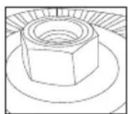
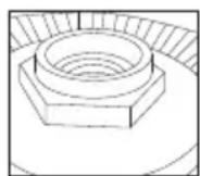
- While depressing spindle lock button 3, thread the sanding clamp nut 30 on spindle, piloting the raised hub on the clamp nut into the center of sanding disc and backing pad.
- Tighten the clamp nut by hand. Then depress the spindle lock button while turning the sanding disc until the sanding disc and clamp nut are snug.
- To remove the wheel, grasp and turn the backing pad and sanding pad while depressing the spindle lock button.
Mounting and Removing Hubbed Wheels (Fig. A)
Hubbed wheels install directly on the spindle. Thread of accessory must match thread of spindle.
- If it is not needed, remove the backing flange by pulling it away from tool.
IMPORTANT: Removing the backing flange should only be done if the hubbed accessory has recessed portion of the threads that clear the unthreaded portion of the spindle.
Non-recessed threads
Use with backing flange
Recessed threads
Remove backing flange
- Thread the wheel on the spindle 4 by hand.
-
Depress the spindle lock button 3 and use a wrench to tighten the hub of the wheel.
-
Reverse the above procedure to remove the wheel.
NOTICE: Failure to properly seat the wheel before turning the tool on may result in damage to the tool or the wheel.
Mounting Wire Cup Brushes and Wire Wheels (Fig. A)
WARNING: Failure to properly seat the brush/wheel could result in serious injury (or damage to the tool or wheel).
AUTION: To reduce the risk of personal injury, wear work gloves when handling wire brushes and wheels.
They can become sharp.
AUTION: To reduce the risk of damage to the tool, wheel or brush must not touch guard when mounted or while in use. Undetectable damage could occur to the accessory, causing wires to fragment from accessory wheel or cup.
Wire cup brushes or wire wheels install directly on the threaded spindle. Use only wire brushes or wheels provided with a threaded hub. These accessories are available at extra cost from your local dealer or authorized service center.
- Place the tool on a table, guard up.
- If it is not needed, remove the backing flange by pulling it away from tool (Refer to the illustration in Mounting and Removing Hubbed Wheels to determine if the backing flange is needed).
- Thread the wheel on the spindle by hand.
- Depress spindle lock button 3 and use a wrench on the hub of the wire wheel or brush to tighten the wheel.
- To remove the wheel, reverse the above procedure.
NOTICE: To reduce the risk of damage to the tool, properly seat the wheel hub before turning the tool on.
Threaded Flange Holder (Fig. J)
DCG400
The threaded flange holder 18 comes installed on some models, and is designed to hold the unused 3/8" arbor locking flange 7 or the 5/8" arbor locking flange 8.
Prior to Operation
• Install the guard and appropriate disc or wheel. Do not use excessively worn discs or wheels.
- Be sure the backing flange and locking flange are mounted correctly. Follow the instructions given in the Accessories Chart.
- Make sure the disc or wheel rotates in the direction of the arrows on the accessory and the tool.
- Do not use a damaged accessory. Before each use inspect the accessory such as abrasive wheels for chips and cracks, backing pad for cracks, tear or excess wear, wire brush for loose or cracked wires. If power tool or accessory is dropped, inspect for damage or install an undamaged accessory. After inspecting and installing an accessory, position yourself and bystanders away from the plane of the rotating accessory and run the power tool at maximum no-load speed for one minute. Damaged accessories will normally break apart during this test time.
OPERATION
WARNING: To reduce the risk of serious personal injury, turn unit off and remove the battery pack before making any adjustments or removing/installing attachments or accessories. An accidental start-up can cause injury.
Installing and Removing the Battery Pack (Fig. K)
NOTE: For best results, make sure your battery pack is fully charged.
To install the battery pack 14 into the tool handle, align the battery pack with the rails inside the tool's handle and slide it into the handle until the battery pack is firmly seated in the tool and ensure that it does not disengage.
To remove the battery pack from the tool, press the release button 15 and firmly pull the battery pack out of the tool handle. Insert it into the charger.
Proper Hand Position (Fig. L, M)
WARNING: To reduce the risk of serious personal injury, ALWAYS use proper hand position as shown.
WARNING: To reduce the risk of serious personal injury, ALWAYS hold securely in anticipation of a sudden reaction.
DCG400
Proper hand position requires one hand on the body of the tool 32, as shown in Figure L.
DCG402
Proper hand position requires one hand on the side handle 5, with the other hand on the body of the tool 32, as shown in Figure M.
Paddle Switch (Fig. A)
AUTION: Hold the side handle (DCG402) and body of the tool firmly to maintain control of the tool at start-up and during use and until the wheel or accessory stops rotating. Make sure the wheel has come to a complete stop be fore laying the tool down.
CAUTION: Before inserting the battery, depress and release the paddle switch 1 once to ensure that the switch is off. Depress and release the paddle switch as described below after any interruption in power supply to the tool, such as motor overload, pinch, stall or bind-up event, or any other unexpected tool shutdown.
NOTE: To reduce unexpected tool movement, do not switch the tool on or off while under load conditions. Allow the grinder to run up to full speed before touching the work surface. Lift the tool from the surface before turning the tool off. Allow the tool to stop rotating before putting it down.
- To turn the tool on, push the lock-off lever 2 toward the front (gear case) of the tool, then depress the paddle switch 1. The tool will run while the switch is depressed.
- Turn the tool off by releasing the paddle switch.
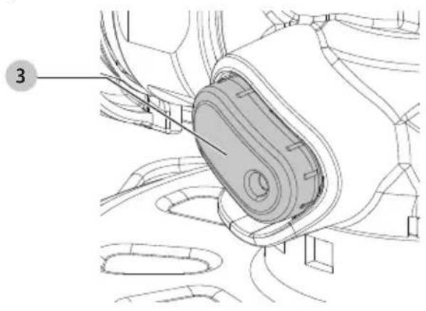
Spindle Lock Button (Fig. N)
The spindle lock button 3 is provided to prevent the spindle from rotating when installing or removing wheels. Operate the spindle lock only when the tool is turned off, when the battery has been removed, and has come to a complete stop.
NOTICE: To reduce the risk of damage to the tool, do not engage the spindle lock while the tool is operating. Damage to the tool will result and attached accessory may spin off possibly resulting in injury.
To engage the lock, depress the spindle lock button 3 and rotate the spindle until you are unable to rotate the spindle further.
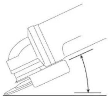
Surface Grinding, Sanding and Wire Brushing (Fig. 0)
AUTION: Always use the correct guard per the instructions in this manual.
To perform work on the surface of a workpiece:
- Allow the tool to reach full speed before touching the tool to the work surface.
- Apply minimum pressure to the work surface, allowing the tool to operate at high speed. Material removal rate is greatest when the tool operates at high speed.
- Maintain an appropriate angle between the tool and work surface. Refer to the chart according to particular function.
| Function Angle | |
| Grinding 20°-30° | |
| Sanding with Flap Disc 5°-10° | |
| Sanding with Backing Pad 5°-15° | |
| Wire Brushing 5°-10° | |
-
Maintain contact between the edge of the wheel and the work surface.
-
If grinding, sanding with flap discs or wire brushing move the tool continuously in a forward and back motion to avoid creating gouges in the work surface.
- If sanding with a backing pad, move the tool constantly in a straight line to prevent burning and swirling of work surface.
NOTE: Allowing the tool to rest on the work surface without moving will damage the work piece.
- Remove the tool from work surface before turning tool off. Allow the tool to stop rotating before laying it down.
SAUTION: Use extra care when working over an edge, as a sudden sharp movement of grinder may be experienced.
Precautions To Take When Working on a Painted Workpiece
- Sanding or wire brushing of lead-based paint is NOT RECOMMENDED due to the difficulty of controlling the contaminated dust. The greatest danger of lead poisoning is to children and pregnant women.
- Since it is difficult to identify whether or not a paint contains lead without a chemical analysis, we recommend the following precautions when sanding any paint:
Personal Safety
- No children or pregnant women should enter the work area where the paint sanding or wire brushing is being done until all clean up is completed.
- A dust mask or respirator should be worn by all persons entering the work area. The filter should be replaced daily or whenever the wearer has difficulty breathing.
NOTE: Only those dust masks suitable for working with lead paint dust and fumes should be used. Ordinary painting masks do not offer this protection. See your local hardware dealer for the proper NIOSH-approved mask.
- NO EATING, DRINKING or SMOKING should be done in the work area to prevent ingesting contaminated paint particles. Workers should wash and clean up BEFORE eating, drinking or smoking. Articles of food, drink, or smoking should not be left in the work area where dust would settle on them.
ENGLISH
Environmental Safety
- Paint should be removed in such a manner as to minimize the amount of dust generated.
- Areas where paint removal is occurring should be sealed with plastic sheeting of 4 mils thickness.
- Sanding should be done in a manner to reduce tracking of paint dust outside the work area.
Cleaning and Disposal
- All surfaces in the work area should be vacuumed and thoroughly cleaned daily for the duration of the sanding project. Vacuum filter bags should be changed frequently.
- Plastic drop cloths should be gathered up and disposed of along with any dust chips or other removal debris. They should be placed in sealed refuse receptacles and disposed of through regular trash pick-up procedures. During clean up, children and pregnant women should be kept away from the immediate work area.
- All toys, washable furniture and utensils used by children should be washed thoroughly before being used again.
Edge Grinding and Cutting (Fig. P)
WARNING: Do not use edge grinding/cutting wheels for surface grinding applications because these wheels are not designed for side pressures encountered with surface grinding. Wheel breakage and injury may result.
AUTION: Wheels used for edge grinding and cutting may break or kick back if they bend or twist while the tool is being used. In all edge grinding/cutting operations, the open side of the guard must be positioned away from the operator.
NOTICE: Edge grinding/cutting with a Type 27 wheel must be limited to shallow cutting and notching—less than 1/2" (13 mm) in depth when the wheel is new. Reduce the depth of cutting/notching equal to the reduction of the wheel radius as it wears down. Refer to the Accessories Chart for more information. Edge grinding/cutting with a Type 41 wheel requires usage of a Type 1 guard.
- Allow the tool to reach full speed before touching the tool to the work surface.
- Apply minimum pressure to the work surface, allowing the tool to operate at high speed. Grinding/cutting rate is greatest when the tool operates at high speed.
- Position yourself so that the open-underside of the wheel is facing away from you.
- Once a cut is begun and a notch is established in the workpiece, do not change the angle of the cut. Changing the angle will cause the wheel to bend and may cause wheel breakage. Edge grinding wheels are not designed to withstand side pressures caused by bending.
- Remove the tool from the work surface before turning the tool off. Allow the tool to stop rotating before laying it down.
MAINTENANCE
WARNING: To reduce the risk of serious personal injury, turn unit off and remove the battery pack before making any adjustments or removing/installing attachments or accessories. An accidental start-up can cause injury.
Your DrWALT power tool has been designed to operate over a long period of time with a minimum of maintenance. Continuous satisfactory operation depends upon proper tool care and regular cleaning.
Cleaning
WARNING: Blow dirt and dust out of all air vents with clean, dry air at least once a week. To minimize the risk of eye injury, always wear ANSI Z87.1 approved eye protection when performing this procedure.
WARNING: Never use solvents or other harsh chemicals for cleaning the non-metallic parts of the tool. These chemicals may weaken the plastic materials used in these parts. Use a cloth dampened only with water and mild soap. Never let any liquid get inside the tool; never immerse any part of the tool into a liquid.
Accessories
WARNING: Since accessories, other than those offered by DeWALT, have not been tested with this product, use of such accessories with this product could be hazardous. To reduce the risk of injury, only DeWALT recommended accessories should be used with this product.
WARNING: Do not use a bonded abrasive wheel that is past its expiration (EXP) date as marked near center of wheel, if provided. Expired wheels are more likely to burst and cause serious injury. Store bonded abrasive wheels in dry location without temperature or humidity extremes. Destroy expired or damaged wheels so they cannot be used.
Recommended accessories for use with your product are available at extra cost from your local dealer or authorized service center. If you need assistance in locating any accessory, please contact DEWALT. Call 1-800-4-DEWALT (1-800-433-9258) or visit our website: www.dewalt.com.
WARNING: Accessories must be rated for at least the speed recommended on the tool warning label. Wheels and other accessories running over their rated accessory speed may fly apart and cause injury. Threaded accessories must have a 5/8"-11 hub. Every unthreaded accessory must have a 7/8" (22.2 mm) arbor hole. If it does not, it may have been designed for a circular saw. Use only the accessories shown in the Accessories Chart of this manual. Accessory ratings must always be above tool speed as shown on tool nameplate.
Repairs
The charger and batteries are not serviceable. There are no serviceable parts inside the charger or battery pack.
WARNING: To assure product SAFETY and RELIABILITY, repairs, maintenance and adjustment (including brush inspection and replacement, when applicable) should be performed by a factory service center or an authorized service center. Always use identical replacement parts.
Register Online
Thank you for your purchase. Register your product now for:
- WARRANTY SERVICE: Registering your product will help you obtain more efficient warranty service in case there is a problem with your product.
- CONFIRMATION OF OWNERSHIP: In case of an insurance loss, such as fire, flood or theft, your registration of ownership will serve as your proof of purchase.
- FOR YOUR SAFETY: Registering your product will allow us to contact you in the unlikely event a safety notification is required under the Federal Consumer Safety Act. Register online at www.dewalt.com/account-login.
Three-Year Limited Warranty
For warranty terms, go to
www.dewalt.com/support/warranty.
To request a written copy of the warranty terms, contact: Customer Service at DEWALT Industrial Tool Co., 701 East Joppa Road, Towson, MD 21286 or call 1-800-4-DEWALT (1-800-433-9258).
LATIN AMERICA: This warranty does not apply to products sold in Latin America. For products sold in Latin America, see country-specific warranty information contained in the packaging, call the local company or see website for warranty information.
FREE WARNING LABEL REPLACEMENT: If your warning labels become illegible or are missing, call 1-800-4-DEWALT (1-800-433-9258) for a free replacement.
Additional Information for Guards and Accessories
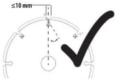
When using segmented diamond wheels, use only diamond wheels with a peripheral gap not greater than 10 mm and negative rake angle.
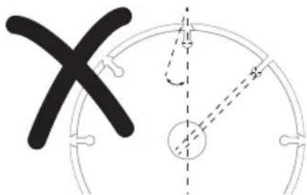
DO NOT USE
segmented diamond wheels with a peripheral gap greater than 10 mm and/or a positive rake angle.
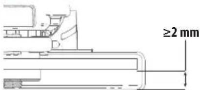
For all grinding, sanding, and wheel type wire brushing accessories, the lowest portion of the accessory must be contained within the guard enclosure with 2 mm or greater clearance to the bottom lip of guard.
DCG400, DCG402 ACCESSORIES CHART
| Approved wheels for (DCG400, DCG402) | |
| Type 1 / T1Type 41 / T41 | 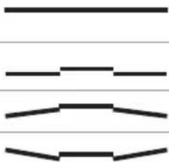 |
| Type 27 / T27 | |
| Type 28 / T28† | |
| Type 29 / T29 | |
| Non-approved wheels for (DCG400, DCG402) | |
| Type 11 / T11 |  |
| Type 6 / T6 |  |
Type 27 Hubbed Grinding Wheels (DCG402 only)
| 4.5" Type 27/Type B guard (NA568029) |  | 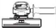 |
| Type 27 hubbed wheel | 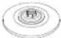 |
Type 27, 28 Depressed Center Grinding Wheels (DCG400 only)
| 4" Type 27/Type B guard (NA568026) | 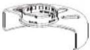 | 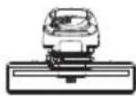 |
| Reversible backing flange (NA734316) |  | |
| Type 27, 28 depressed center wheel |  | |
| 3/8" arbor locking flange (NA376069) |  | |
| 5/8" arbor locking flange (NA736101) |  |
Type 27, 28 Depressed Center Grinding Wheels (DCG402 only)
| Type 27/Type B guardNA568029 (4.5") | 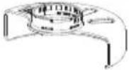 | 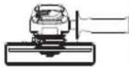 |
| Backing flange:N115381 |  | |
| Type 27, 28 depressedcenter wheel |  | |
| Locking flange: N452728 |  |
Hubbed Sanding Flap Discs (DCG402 only)
| 4.5" Type 27/Type B guard (NA568029) | 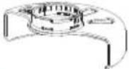 | 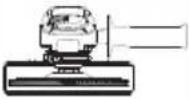 |
| Hubbed sanding flap disc | 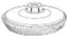 | |
| Non-Hubbed Sanding Flap Discs (DCG400 only) | ||
| 4" Type 27/Type B guard (NA568026) | 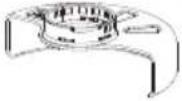 | 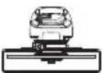 |
| Reversible backing flange (NA734316) |  | |
| Non-Hubbed sanding flap disc | 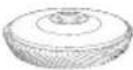 | |
| 3/8" arbor locking flange (NA736069) |  | |
| 5/8" arbor locking flange (NA736101) |  | |
| Non-Hubbed Sanding Flap Discs (DCG402 only) | ||
| 4.5" Type 27/Type B guard (NA568029) | 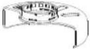 | 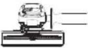 |
| Backing flange (N115381) |  | |
| Non-Hubbed sanding flap disc | 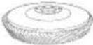 | |
| Locking flange (N452728) |  | |
| Hubbed Wire Wheels (DCG402 only) | ||
| 4.5" Type 27/Type B guard (NA568029) | 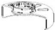 | 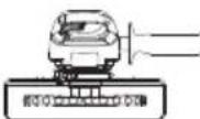 |
| Hubbed wire wheel |  | |
| Type 1/41 Cutting Wheels (DCG400) | ||
| 4" Type B guard with Type A Clip-On guard (NA724847) | 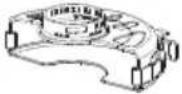 | 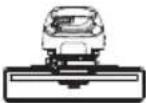 |
| Reversible backing flange (NA734316) | ||
| Type 1/41 abrasive cutting wheel | ||
| 3/8" arbor locking flange (NA736069) | ||
| 5/8" arbor locking flange (NA736101) | ||
| Type 1/41 Cutting Wheels (DCG402) | ||
| 4.5" Type 1/41/Type A guard(N311419**) | 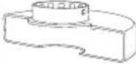 | 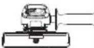 |
| 4.5" Type B guardwith Type A Clip-Onguard (NA766918) | 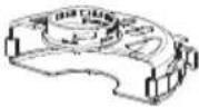 | |
| Backing flange(N115381) |  | |
| Type 1/41 abrasivecutting wheel |  | |
| Locking flange(N452728) |  | |
| Diamond Cutting Wheels (metal) (DCG400) | ||
| 4" Type B guard withType A Clip-On guard(NA724847) | 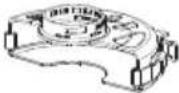 | 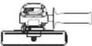 |
| Reversible backingflange (NA734316) |  | |
| Diamond cutting wheel | 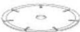 | |
| 3/8" arbor lockingflange (NA736069) |  | |
| 5/8" arbor lockingflange (NA736101) |  | |
| Diamond Cutting Wheels (metal cutting) (DCG402) | ||
| 4.5" Type 1/41/Type A guard(N311419**) | 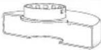 | 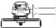 |
| 4.5" Type B guardwith Type A Clip-Onguard (NA766918) | 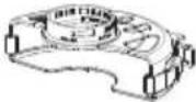 | |
| Backing flange(N115381) |  | |
| Diamond cutting wheel(metal cutting) | 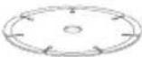 | |
| Locking flange(N452728) |  | |
Diamond Cutting Wheels (metal) (DCG400)
Hubbed Wire Wheels (DCG402 only)
Type 1/41 Cutting Wheels (DCG400)
| Sanding Discs (DCG402 only) | ||
| Backing flange(N115381) |  | 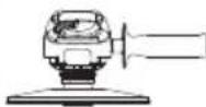 |
| 4.5" rubber backing pad (DABP4RR58**) | 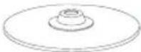 | |
| Sanding disc |  | |
| Sanding clamp nut(Included with rubber backing pad DABP4RR58**) |  | |
| Hubbed Wheel Wrench | ||
| Hubbed wheel wrench (N541784**) | ||
Hubbed Wheel Wrench
| Hubbed wheel wrench (N541784**) | 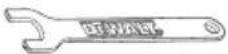 |
Type 1/41/Type A guards or Type B guard with Clip-on guard are intended for use with Type 1/41 cutting wheels and Type 27 wheels marked for cutting only. Grinding with wheels other than Type 27 and Type 29 require different accessory gurds. Always use the smallest proper guard possible that does not contact the accessory.
** NOTE: Available at extra cost from your local dealer or authorized service center.
† NOTE: Type 28 depressed center wheels only.
RANGER: Do not use for wood cutting or woodcarving. Do not use toothed blades of any kind. Serious injury can result.
natural_image
Illustration of wooden logs and a gear mechanism inside a circular frame (no text or symbols)Usage Prévu
NE PAS UTILISER
Non-approved wheels for (DCG400, DCG402)
| Type 11 / T11 |  |
| Type 6 / T6 |  |
natural_image
Illustration of wood grain and a log with gear-like patterns (no text or symbols)Uso Debido
Eje Central Lázaro Cárdenas No. 18 - Local (55) 5588 9377 D, Col. Obrera
MERIDA, YUC
Calle 63 #459-A - Col. Centro (999) 928 5038
MONTERREY, N.L.
Av. Francisco I. Madero 831 Poniente - Col. (818) 375 23 13 Centro
PUEBLA, PUE
17 Norte #205 - Col. Centro (222) 246 3714
QUERETARO, QRO
Av. San Roque 274 - Col. San Gregorio (442) 2 17 63 14
SAN LUIS POTOSI, SLP
Col. Santa Fe Alvaro Obregon,
Ciudad de Mexico, Mexico.
C.P 01210
TEL(52) 55 53267100
R.F.C.BDE8106261W7
Registro en Línea
natural_image
Illustration of wood logs and two circular gear-like symbols (no text or labels)Compatible battery packs and chargers / Blocs-piles et chargeurs compatibles / Baterías y cargadores compatibles
| Battery PacksBlocs-pilesBaterías | DCB201, DCB203, DCB203G, DCB204, DCB204BT, DCB205, DCB205G, DCB205BT, DCB205BTLR, DCB206, DCB208, DCB210, DCB230, DCB240, DCBP034, DCBP034G, DCBP320, DCBP520, DCBP520G, DCB520LR |
| ChargersChargeursCargadores | DCB094, DCB102, DCB103, DCB104, DCB107, DCB112, DCB113, DCB115, DCB118, DCB132, DCB1102, DCB1104, DCB1106, DCB1112, DWST08050 |
WARNING: Use of any other battery packs may create a risk of injury and fire.
NOTE: DO NOT charge when the battery pack is below 40 °F ( 4.5 °C ) or above 104 °F ( 40 °C ). Do not store or use the tool and battery pack in locations where the temperature may reach or exceed 104 °F ( 40 °C ).