
DCG416V - Grinder DEWALT - Free user manual and instructions
Find the device manual for free DCG416V DEWALT in PDF.

| Product type | Cordless angle grinder |
| Brand | DeWalt |
| Model | DCG416V |
| Power source | Cordless, 20 V max lithium-ion battery |
| Nominal voltage | 20 V max (18 V nominal) |
| Variable speed | Yes, continuous electronic adjustment via thumbwheel |
| Maximum wheel diameter | 125 mm (5 in) |
| Compatible wheel types | Type 27, Type 1/41, Type 28 (not recommended), Type 29 |
| Auxiliary handle | Yes, removable and adjustable (2 positions) |
| Guard | With release lever, tool-free adjustable (One‑Touch) |
| Electronic clutch (E‑Clutch) | Yes, cuts power in case of overload to reduce reaction torque |
| Kickback Brake | Yes, quickly stops the wheel in case of binding |
| Soft start | Yes, limits startup current |
| Wireless control (Tool Connect) | Yes, allows pairing with a dust extractor or other tool |
| Spindle lock system | Yes, for easy disc change |
| Switch | Paddle switch (DCG416V model) |
| Weight (with battery) | Approximately 2.7 kg (estimated) |
| Dimensions (L x W x H) | Approximately 30 x 10 x 15 cm (estimated) |
| Warranty | 3 years (limited) |
| Main applications | Grinding, sanding, wire brushing, cutting |
Frequently Asked Questions - DCG416V DEWALT
User questions about DCG416V DEWALT
0 question about this device. Answer the ones you know or ask your own.
Ask a new question about this device
Download the instructions for your Grinder in PDF format for free! Find your manual DCG416V - DEWALT and take your electronic device back in hand. On this page are published all the documents necessary for the use of your device. DCG416V by DEWALT.
USER MANUAL DCG416V DEWALT
English (original instructions) 4
1 Paddle switch
2 Slide switch
3 Lock-off lever
4 Spindle lock button
5 Spindle
6 Auxiliary handle
7 Backing flange
8 Locking flange
9 Guard
10 Guard release lever
11 Variable speed dial
12 Battery pack
13 Battery release button
natural_image
Technical line drawing of a mechanical component with 90-degree angular annotations (no text or symbols on the diagram itself)Fig. F Fig. G
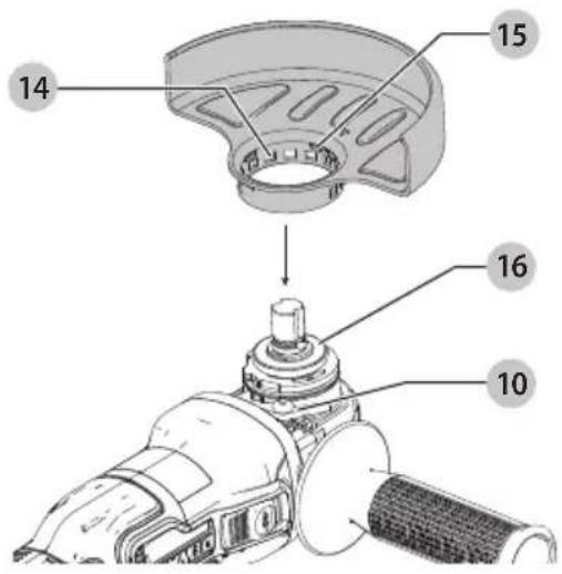
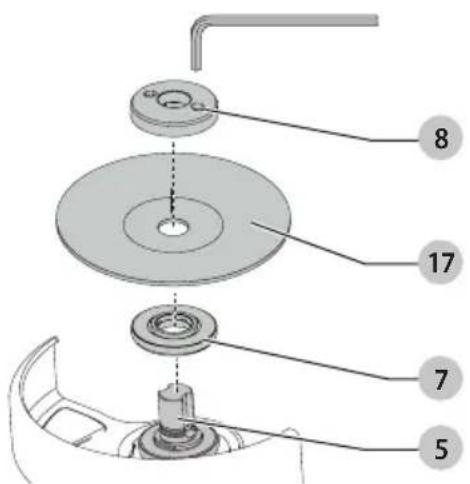
Fig. H
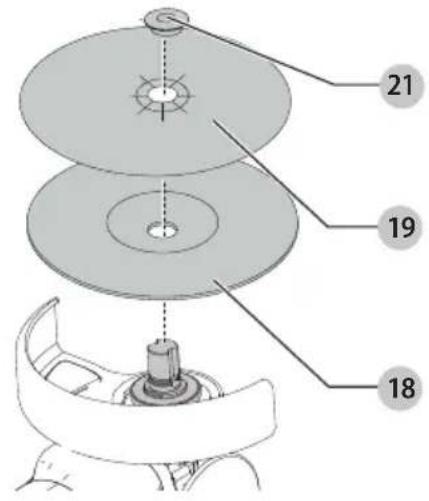
Fig.1
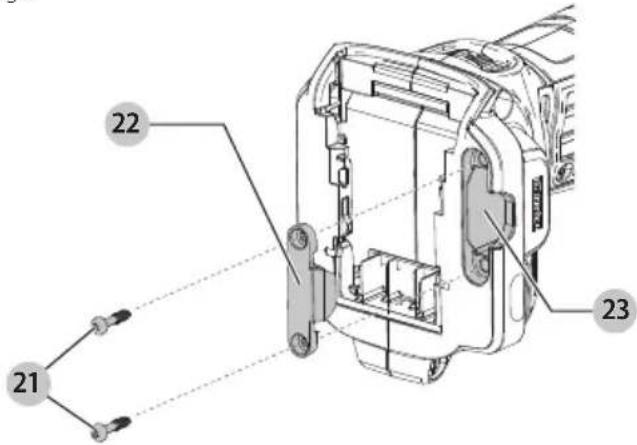
Fig. J
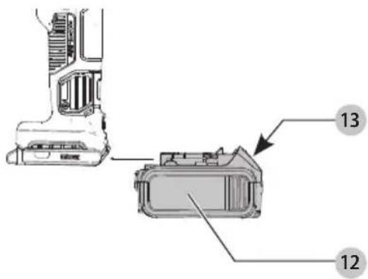
Fig. K
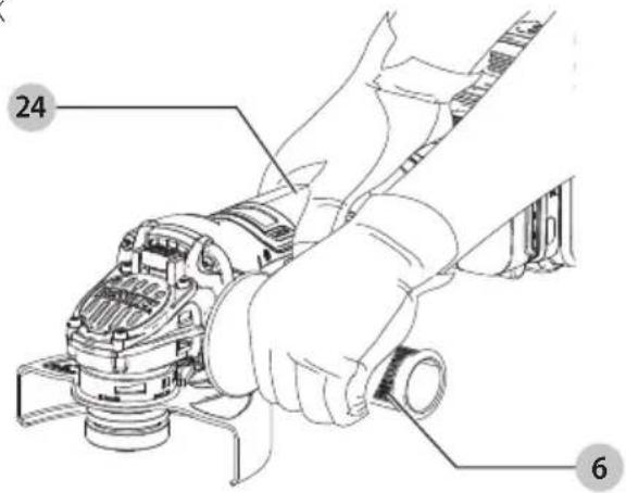
Fig. L
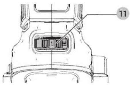
Fig. M
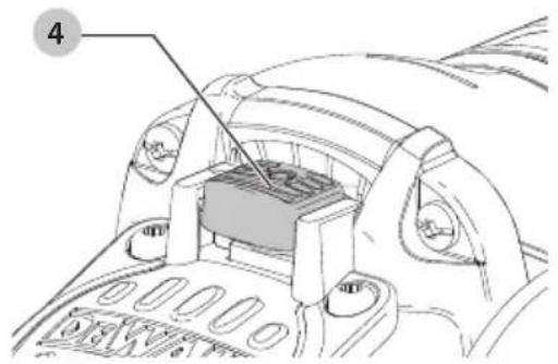
Fig. N Fig. O
natural_image
Technical line drawing of a mechanical assembly with a tool and base, no text or symbols present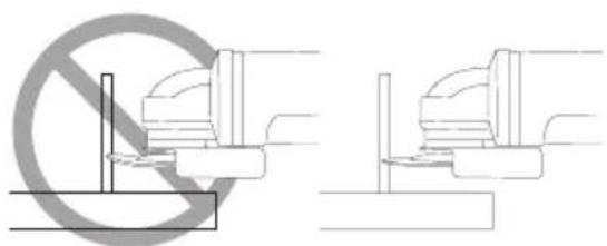
natural_image
Two technical diagrams showing a no-smoking symbol and a mechanical assembly with no visible text or labels.English
WARNING: Read all safety warnings and all instructions. Failure to follow the warnings and instructions may result in electric shock, fire and/or serious injury.

WARNING: To reduce the risk of injury, read the instruction manual.
Intended Use
This heavy-duty medium angle grinder has been designed for professional grinding, sanding, wire brush, and cut-off applications at various work sites (i.e., construction sites).
DO nOT use under wet conditions or in presence of flammable liquids or gases.
These heavy-duty small angle grinders are professional power tools. DO nOT let children come into contact with the tool. Supervision is required when inexperienced operators use this tool.
Definitions: Safety Alert Symbols and Words
This instruction manual uses the following safety alert symbols and words to alert you to hazardous situations and your risk of personal injury or property damage.
DANGER: Indicates an imminently hazardous sedation which, if not avoided, will result in death or serious injury.
WARNING: Indicates a potentially hazardous situation which, if not avoided, could result in death or serious injury.
CAUTION: Indicates a potentially hazardous situation which, if not avoided, may result in minor or moderate injury.
(### without word) Indicates a safety related message.
NOTICE: Indicates a practice not related to personal injury which, if not avoided, may result in property damage.
GENERAL POWER TOOL SAFETY WARNINGS
WARNING: Read all safety warnings, instructions, indications and specifications provided with this power tool. Failure to follow all instructions listed below may result in electric shock, fire and/or serious injury.
SAVE ALL WARNINGS AND INSTRUCTIONS FOR FUTURE REFERENCE.
The term "power tool" in the warnings refers to your mains-operated (corded) power tool or battery-operated (cordless) power tool.
1) Work Area Safety
a) Keep work area clean and well lit. Cluttered or dark areas invite accidents.
b) Do not operate power tools in explosive atmospheres, such as in the presence of flammable liquids, gases or dust. Power tools create sparks which may ignite the dust or fumes.
c) Keep children and bystanders away while operating a power tool. Distractions can cause you to lose control.
2) Electrical Safety
a) Power tool plugs must match the outlet. Never modify the plug in any way. Do not use any adapter plugs with earthed (grounded) power tools. Unmodified plugs and matching outlets will reduce risk of electric shock.
b) Avoid body contact with earthed or grounded surfaces, such as pipes, radiators, ranges and refrigerators. There is an increased risk of electric shock if your body is earthed or grounded.
c) Do not expose power tools to rain or wet conditions. Water entering a power tool will increase the risk of electric shock.
d) Do not abuse the cord. Never use the cord for carrying, pulling or unplugging the power tool. Keep cord away from heat, oil, sharp edges or moving parts. Damaged or entangled cords increase the risk of electric shock.
e) When operating a power tool outdoors, use an extension cord suitable for outdoor use. Use of a cord suitable for outdoor use reduces the risk of electric shock.
f) If operating a power tool in a damp location is unavoidable, use a ground fault circuit interrupter (GFCI) protected supply. Use of a GFCI reduces the risk of electric shock.
3) Personal Safety
a) Stay alert, watch what you are doing and use common sense when operating a power tool. Do not use a power tool while you are tired or under the influence of drugs, alcohol or medication. A moment of inattention while operating power tools may result in serious personal injury.
b) Use personal protective equipment. Always wear eye protection. Protective equipment such as a dust mask, non-skid safety shoes, hard hat, or hearing protection used for appropriate conditions will reduce personal injuries.
c) Prevent unintentional starting. Ensure the switch is in the off-position before connecting to power source and/or battery pack, picking up or carrying the tool. Carrying power tools with your finger on the switch or energizing power tools that have the switch on invites accidents.
d) Remove any adjusting key or wrench before turning the power tool on. A wrench or a key left attached to a rotating part of the power tool may result in personal injury.
e) Do not overreach. Keep proper footing and balance at all times. This enables better control of the power tool in unexpected situations.
f) Dress properly. Do not wear loose clothing or jewelry. Keep your hair, clothing and gloves away from moving parts. Loose clothes, jewelry or long hair can be caught in moving parts.
g) If devices are provided for the connection of dust extraction and collection facilities, ensure these are connected and properly used. Use of dust collection can reduce dust-related hazards.
h) Do not let familiarity gained from frequent use of tools allow you to become complacent and ignore tool safety principles. A careless action can cause severe injury within a fraction of a second.
4) Power Tool Use and Care
a) Do not force the power tool. Use the correct power tool for your application. The correct power tool will do the job better and safer at the rate for which it was designed.
b) Do not use the power tool if the switch does not turn it on and off. Any power tool that cannot be controlled with the switch is dangerous and must be repaired.
c) Disconnect the plug from the power source and/or remove the battery pack, if detachable, from the power tool before making any adjustments, changing accessories, or storing power tools. Such preventive safety measures reduce the risk of starting the power tool accidentally.
d) Store idle power tools out of the reach of children and do not allow persons unfamiliar with the power tool or these instructions to operate the power tool. Power tools are dangerous in the hands of untrained users.
e) Maintain power tools and accessories. Check for misalignment or binding of moving parts, breakage of parts and any other condition that may affect the power tool's operation. If damaged, have the power tool repaired before use. Many accidents are caused by poorly maintained power tools.
f) Keep cutting tools sharp and clean. Properly maintained cutting tools with sharp cutting edges are less likely to bind and are easier to control.
g) Use the power tool, accessories and tool bits etc. in accordance with these instructions, taking into account the working conditions and the work to be performed. Use of the power tool for operations different from those intended could result in a hazardous situation.
h) Keep handles and grasping surfaces dry, clean and free from oil and grease. Slippery handles and grasping surfaces do not allow for safe handling and control of the tool in unexpected situations.
5) Battery Tool Use and Care
a) Recharge only with the charger specified by the manufacturer. A charger that is suitable for one type of battery pack may create a risk of fire when used with another battery pack.
b) Use power tools only with specifically designated battery packs. Use of any other battery packs may create a risk of injury and fire.
c) When battery pack is not in use, keep it away from other metal objects, like paper clips, coins,
keys, nails, screws or other small metal objects, that can make a connection from one terminal to another. Shorting the battery terminals together may cause burns or a fire.
d) Under abusive conditions, liquid may be ejected from the battery; avoid contact. If contact accidentally occurs, flush with water. If liquid contacts eyes, additionally seek medical help. Liquid ejected from the battery may cause irritation or burns.
e) Do not use a battery pack or tool that is damaged or modified. Damaged or modified batteries may exhibit unpredictable behavior resulting in fire, explosion or risk of injury.
f) Do not expose a battery pack or tool to fire or excessive temperature. Exposure to fire or temperature above 265 °F (130 °C) may cause explosion.
g) Follow all charging instructions and do not charge the battery pack or tool outside the temperature range specified in the instructions. Charging improperly or at temperatures outside the specified range may damage the battery and increase the risk of fire.
6) Service
a) Have your power tool serviced by a qualified repair person using only identical replacement parts. This will ensure that the safety of the power tool is maintained.
b) Never service damaged battery packs. Service of battery packs should only be performed by the manufacturer or authorized service providers.
SAFETY INSTRUCTIONS FOR ALL OPERATIONS
Safety Warnings Common for Grinding, Sanding, Wire Brushing, or Cutting-Off Operations:
a) This power tool is intended to function as a grinder, sander, wire brush, or cut-off tool. Read all safety warnings, instructions, illustrations and specifications provided with this power tool. Failure to follow all instructions listed below may result in electric shock, fire and/or serious injury.
b) Operations such as polishing are not recommended to be performed with this power tool. Operations for which the power tool was not designed may create a hazard and cause personal injury.
c) Do not convert this power tool to operate in a way which is not specifically designed and specified by the tool manufacturer. Such a conversion may result in a loss of control and cause serious personal injury.
d) Do not use accessories which are not specifically designed and specified by the tool manufacturer.
English
Just because the accessory can be attached to your power tool, it does not assure safe operation.
e) The rated speed of the accessory must be at least equal to the maximum speed marked on the power tool. Accessories running faster than their rated speed can break and fly apart.
f) The outside diameter and the thickness of your accessory must be within the capacity rating of your power tool. Incorrectly sized accessories cannot be adequately guarded or controlled.
g) The dimensions of the accessory mounting must fit the dimensions of the mounting hardware of the power tool. Accessories that do not match the mounting hardware of the power tool will run out of balance, vibrate excessively and may cause loss of control.
h) Do not use a damaged accessory. Before each use inspect the accessory such as abrasive wheels for chips and cracks, backing pad for cracks, tear or excess wear, wire brush for loose or cracked wires. If power tool or accessory is dropped, inspect for damage or install an undamaged accessory. After inspecting and installing an accessory, position yourself and bystanders away from the plane of the rotating accessory and run the power tool at maximum no-load speed for one minute. Damaged accessories will normally break apart during this test time.
i) Wear personal protective equipment. Depending on application, use face shield, safety goggles or safety glasses. As appropriate, wear dust mask, hearing protectors, gloves and workshop apron capable of stopping small abrasive or workpiece fragments. The eye protection must be capable of stopping flying debris generated by various applications. The dust mask or respirator must be capable of filtrating particles generated by the particular application. Prolonged exposure to high intensity noise may cause hearing loss.
j) Keep bystanders a safe distance away from work area. Anyone entering the work area must wear personal protective equipment. Fragments of workpiece or of a broken accessory may fly away and cause injury beyond immediate area of operation.
k) Hold the power tool by insulated gripping surfaces only, when performing an operation where the cutting accessory may contact hidden wiring. Cutting accessory contacting a "live" wire may make exposed metal parts of the power tool "live" and could give the operator an electric shock.
1) Never lay the power tool down until the accessory has come to a complete stop. The spinning accessory may grab the surface and pull the power tool out of your control.
m) Do not run the power tool while carrying it at your side. Accidental contact with the spinning accessory could snag your clothing, pulling the accessory into your body.
n) Regularly clean the power tool's air vents. The motor's fan will draw the dust inside the housing and excessive accumulation of powdered metal may cause electrical hazards.
o) Do not operate the power tool near flammable materials. Sparks could ignite these materials.
p) Do not use accessories that require liquid coolants. Using water or other liquid coolants may result in electrocution or shock.
q) Do not use Type 11 (flaring cup) wheels on this tool. Using inappropriate accessories can result in injury.
r) When starting the tool with a new or replacement wheel, or a new or replacement wire brush installed, hold the tool in a well protected area and let it run for one minute. If the wheel has an undetected crack or flaw, it should burst in less than one minute. If the wire brush has loose wires, they will be detected. Never start the tool with a person in line with the wheel. This includes the operator.
s) Use of accessories not specified in this manual is not recommended and may be hazardous. Use of power boosters that would cause the tool to be driven at speeds greater than its rated speed constitutes misuse.
Kickback and Related Warnings:
Kickback is a sudden reaction to a pinched or snagged rotating wheel, backing pad, brush or any other accessory. Pinching or snagging causes rapid stalling of the rotating accessory which in turn causes the uncontrolled power tool to be forced in the direction opposite of the accessory's rotation at the point of the binding.
For example, if an abrasive wheel is snagged or pinched by the workpiece, the edge of the wheel that is entering into the pinch point can dig into the surface of the material causing the wheel to climb out or kick out. The wheel may either jump toward or away from the operator, depending on direction of the wheel's movement at the point of pinching. Abrasive wheels may also break under these conditions.
Kickback is the result of power tool misuse and/or incorrect operating procedures or conditions and can be avoided by taking proper precautions as given below.
a) Maintain a firm grip with both hands on the power tool and position your body and arms to allow you to resist kickback forces. Always use auxiliary handle, if provided, for maximum control over kickback or torque reaction during start-up. The operator can control torque reactions or kickback forces, if proper precautions are taken.
b) Never place your hand near the rotating accessory. Accessory may kickback over your hand.
c) Do not position your body in the area where power tool will move if kickback occurs. Kickback will propel the tool in direction opposite to the wheel's movement at the point of snagging.
d) Use special care when working corners, sharp edges, etc. Avoid bouncing and snagging the accessory. Corners, sharp edges or bouncing have a tendency to snag the rotating accessory and cause loss of control or kickback.
e) Do not attach a saw chain woodcarving blade, segmented diamond wheel with a peripheral gap greater than 10 mm or toothed saw blade. Such blades create frequent kickback and loss of control.
Safety Warnings Specific for Grinding and Cutting-Off Operations:
a) Use only wheel types that are specified for your power tool and the specific guard designed for the selected wheel. Wheels for which the power tool was not designed cannot be adequately guarded and are unsafe.
b) The grinding surface of center depressed wheels must be mounted below the plane of the guard lip. An improperly mounted wheel that projects through the plane of the guard lip cannot be adequately protected.
c) The guard must be securely attached to the power tool and positioned for maximum safety, so the least amount of wheel is exposed towards the operator. The guard helps to protect the operator from broken wheel fragments, accidental contact with wheel and sparks that could ignite clothing.
d) Wheels must be used only for specified applications. For example: do not grind with the side of cut-off wheel. Abrasive cut-off wheels are intended for peripheral grinding, side forces applied to these wheels may cause them to shatter.
e) Always use undamaged wheel flanges that are of correct size and shape for your selected wheel. Proper wheel flanges support the wheel thus reducing the possibility of wheel breakage. Flanges for cut-off wheels may be different from grinding wheel flanges.
f) Do not use worn down wheels from larger power tools. A wheel intended for larger power tool is not suitable for the higher speed of a smaller tool and may burst.
g) When using dual purpose wheels always use the correct guard for the application being performed. Failure to use the correct guard may not provide the desired level of guarding, which could lead to serious injury.
Additional Safety Warnings Specific for Cutting-Off Operations:
a) Do not "jam" the cut-off wheel or apply excessive pressure. Do not attempt to make an excessive depth of cut. Overstressing the wheel increases the loading and susceptibility to twisting or binding of the wheel in the cut and the possibility of kickback or wheel breakage.
b) Do not position your body in line with and behind the rotating wheel. When the wheel, at the point of operation, is moving away from your body, the possible kickback may propel the spinning wheel and the power tool directly at you.
c) When the wheel is binding or when interrupting a cut for any reason, switch off the power tool and hold it motionless until the wheel comes to a complete stop. Never attempt to remove the cut-off wheel from the cut while the wheel is in motion otherwise kickback may occur. Investigate and take corrective action to eliminate the cause of wheel binding.
d) Do not restart the cutting operation in the workpiece. Let the wheel reach full speed and carefully re-enter the cut. The wheel may bind, walk up or kickback if the power tool is restarted in the workpiece.
e) Support panels or any oversized workpiece to minimize the risk of wheel pinching and kickback. Large workpieces tend to sag under their own weight. Supports must be placed under the workpiece near the line of cut and near the edge of the workpiece on both sides of the wheel.
f) Use extra caution when making a "pocket cut" into existing walls or other blind areas. The protruding wheel may cut gas or water pipes, electrical wiring or objects that can cause kickback.
g) Do not attempt to do curved cutting. Overstressing the wheel increases the loading and susceptibility to twisting or binding of the wheel in the cut and the possibility of kickback or wheel breakage, which can lead to serious injury.
Safety Warnings Specific for Sanding Operations:
a) Use proper sized sanding disc paper. Follow manufacturers recommendations, when selecting sanding paper. Larger sanding paper extending too far beyond the sanding pad presents a laceration hazard and may cause snagging, tearing of the disc or kickback.
Safety Warnings Specific for Wire Brushing Operations:
a) Be aware that wire bristles are thrown by the brush even during ordinary operation. Do not overstress the wires by applying excessive load to the brush. The wire bristles can easily penetrate light clothing and/or skin.
b) If the use of a guard is specified for wire brushing, do not allow any interference of the wire wheel or brush with the guard. Wire wheel or brush may expand in diameter due to work load and centrifugal forces.
Additional Safety Information
WARNING: Never modify the power tool or any part of the damage or personal injury could result.
WARNING: ALWAYS use safety glasses. Everyday eyeglasses are NOT safety glasses. Also use face or dust mask if cutting operation is dusty. ALWAYS WEAR CERTIFIED SAFETY EQUIPMENT:
• ANSI Z87.1 eye protection (CAN/CSA Z94.3),
• ANSI S12.6 (S3.19) hearing protection,
• NIOSH/OSHA/MSHA respiratory protection.
WARNING: Some dust created by power sanding, sanding, grinding, drilling, and other construction activities contains chemicals known to the State of California to cause cancer, birth defects or other reproductive harm. Some examples of these chemicals are:
- lead from lead-based paints,
• crystalline silica from bricks and cement and other masonry products, and
• arsenic and chromium from chemically-treated lumber.
Your risk from these exposures varies, depending on how often you do this type of work. To reduce your exposure to these chemicals: work in a well ventilated area, and work with approved safety equipment, such as those dust masks that are specially designed to grease tube cavity out microscopic particles.
- Wear protective clothing and wash exposed areas with soap and water. Allowing dust to get into your mouth, eyes, or lay on the skin may promote absorption of harmful chemicals. Direct particles away from face and body.
- Use the appropriate dust extractor vacuum to remove the vast majority of static and airborne dust. Failure to remove static and airborne dust could contaminate the working environment or pose an increased health risk to the operator and those in close proximity.
- Use clamps or other practical ways to secure and support the workpiece to a stable platform. Holding the work by hand or against your body is unstable and may lead to loss of control and injury.
• Air vents often cover moving parts and should be avoided. Loose clothes, jewelry or long hair can be caught in moving parts.
CAUTION: When not in use, place tool on its side can be stable surface where it will not cause a tripping or falling hazard. Some tools with large battery packs will stand upright on the battery pack but may be easily knocked over.
The label on your tool may include the following symbols. The symbols and their definitions are as follows:
V....volts
BPM.....beats per minute
Hz ......hertz
=--- or DC.....direct current
minute
Class I Construction (grounded)
RPM......revolutionsper minute
.../min.....per minute
sfpm .... surface feet per minute
SPM ...... strokes per minute
A......amperes
W.....watts
Wh......watt hours
Ah.....amp hours
\~ or AC......alternating current
or AC/DC.... alternating or direct current
☐ Class II Construction (double insulated)
n_0 .....no load speed n .....rated speed
PSI..... pounds per square inch
⊕ earthing terminal
⚠️......safety alert symbol
▲......visible radiation do not stare into the light
E......wearrespiratory protection
wear eye protection
○....wearhearing protection
read all documentation
do not expose to rain
BATTERIES AND CHARGERS
The battery pack is not fully charged out of the carton. Before using the battery pack and charger, read the safety instructions below and then follow charging procedures outlined. When ordering replacement battery packs, be sure to include the catalog number and voltage.
READ ALL INSTRUCTIONS
Important Safety Instructions for All Battery Packs
WARNING: Read all safety warnings, instructions, and cautionary markings for the battery pack, charger and product. Failure to follow the warnings and instructions may result in electric shock, fire and/or serious injury.
- Do not charge or use the battery pack in explosive atmospheres, such as in the presence of flammable liquids, gases or dust. Inserting or removing the battery pack from the charger may ignite the dust or fumes.
- NEVER force the battery pack into the charger. DO NOT modify the battery pack in any way to fit into a non-compatible charger as battery pack may rupture causing serious personal injury. Consult the chart at the end of this manual for compatibility of batteries and chargers.
• Charge the battery packs only in DEWALT chargers.
• DO NOT splash or immerse in water or other liquids. - DO NOT allow water or any liquid to enter battery pack.
- Do not store or use the tool and battery pack in locations where the temperature may reach or exceed 104 °F (40 °C) (such as outside sheds or metal buildings in summer). For best life store battery packs in a cool, dry location.
NOTE: Do not store the battery packs in a tool with the trigger switch locked on. Never tape the trigger switch in the ON position.
- Do not incinerate the battery pack even if it is severely damaged or is completely worn out. The battery pack can explode in a fire. Toxic fumes and materials are created when lithium-ion battery packs are burned.
- Do not expose a battery pack or appliance to fire or excessive temperature. Exposure to fire or temperature above 265 °F (130 °C) may cause explosion.
- Follow all charging instructions and do not charge the battery pack or appliance outside of the temperature range specified in the instructions. Charging improperly or at temperatures outside of the specified range may damage the battery and increase the risk of fire.
- If battery contents come into contact with the skin, immediately wash area with mild soap and water. If battery liquid gets into the eye, rinse water over the open eye for 15 minutes or until irritation ceases. If medical attention is needed, the battery electrolyte is composed of a mixture of liquid organic carbonates and lithium salts.
- Contents of opened battery cells may cause respiratory irritation. Provide fresh air. If symptoms persist, seek medical attention.
- Battery liquid may be flammable if exposed to spark or flame.
- Never attempt to open the battery pack for any reason. If the battery pack case is cracked or damaged, do not insert into the charger. Do not crush, drop or damage the battery pack. Do not use a battery pack or charger that has received a sharp blow, been dropped, run over or damaged in any way (e.g., pierced with a nail, hit with a hammer, stepped on). Damaged battery packs should be returned to the service center for recycling.
Storage Recommendations
The best storage place is one that is cool and dry, away from direct sunlight and excess heat or cold. Store the fully charged battery pack out of the charger.
Battery Pack Cleaning Instructions
Dirt and grease may be removed from the exterior of the battery pack using a cloth or soft non-metallic brush. Do not use water or any cleaning solutions.
Fuel Gauge Battery Packs (Fig. B)
Some battery packs include a fuel gauge. When the fuel gauge button is pressed and held, the LED lights will indicate the approximate level of charge remaining. This does not indicate tool functionality and is subject to variation based on product components, temperature, and end-user application.
Transportation
WARNING: Fire hazard. Do not store, carry, or transport the battery pack so that metal objects can contact exposed battery terminals. For
example, do not place the battery pack in aprons, pockets, tool boxes, product kit boxes, drawers, etc., with loose nails, screws, keys, coins, hand tools, etc. When transporting individual battery packs, make sure that the battery terminals are protected and well insulated from materials that could contact them and cause a short circuit. NOTE: Li-ion battery packs should not be put in checked baggage on airplanes and must be properly protected from short circuits if they are in carry-on baggage.
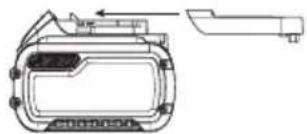
Shipping the DEWALT FLEXVOLT® Battery Pack
The DEWALT FLEXVOLT® battery pack has a battery cap that should be used when shipping the battery pack.
natural_image
Technical line drawing of a mechanical component with no visible text or symbolsAttach the cap to the battery pack to ready it for shipping. This converts the battery pack to three separate 20V batteries. The three batteries have the Watt hour rating labeled "Shipping" on the battery pack. If shipping without the cap or in a tool, the pack is one battery at the Watt hour rating labeled "Use".
Example battery pack label:
USE: 120 Wh SHIPPING: 3 x 40 Wh
In this example, the battery pack is three batteries with 40 Watt hours each when using the cap. Otherwise, the battery pack is one battery with 120 Watt hours.
The RBRC® Seal
Please take your spent battery packs to an authorized DEWALT service center or to your local retailer for recycling. In some areas, it is illegal to place spent battery packs in the trash. You may also contact your local recycling center for information on where to drop off the spent battery pack. Do not place in curbside recycling. For more information visit www.call2recycle.org, or call the toll free number in the RBRC® Seal.
RBRC® is a registered trademark of Call 2 Recycle, Inc.

Important Safety Instructions for All Battery Chargers
WARNING: Read all safety warnings, instructions, and cautionary markings for the battery pack, charger and product. Failure to follow the warnings and instructions may result in electric shock, fire and/or serious injury.
- DO NOT attempt to charge the battery pack with any chargers other than a DEWALT charger. DEWALT chargers and battery packs are specifically designed to work together.
• These chargers are not intended for any uses other than charging DEWALT rechargeable battery packs. Charging other types of battery packs may cause them to overheat and burst, resulting in personal injury, property damage, fire, electric shock or electrocution. - Do not expose the charger to rain or snow.
- Do not allow water or any liquid to enter charger.
- Pull by the plug rather than the cord when disconnecting the charger. This will reduce the risk of damage to the electric plug and cord.
• Make sure that the cord is located so that it will not be stepped on, tripped over or otherwise subjected to damage or stress. - Do not use an extension cord unless it is absolutely necessary. Use of improper extension cord could result in risk of fire, electric shock or electrocution.
ENGLISH
- When operating a charger outdoors, always provide a dry location and use an extension cord suitable for outdoor use. Use of a cord suitable for outdoor use reduces the risk of electric shock.
- An extension cord must have adequate wire size (AWG or American Wire Gauge) for safety. The smaller the gauge number of the wire, the heavier the cord and thus the greater its capacity. An undersized cord will cause a drop in line voltage resulting in loss of power and overheating. The following table shows the correct size to use depending on total length of all extension cords plugged together, and nameplate ampere rating. If in doubt, use the next heavier gauge.
Minimum Gauge for Cord Sets
| Volts | Total Length of Cord in Feet (meters) | ||||
| 120V 25 (7.6) | 50 (15.2) 100 | (30.5) 150 (45.7) | |||
| Ampere Rating | American Wire Gauge | ||||
| More Than Not More Than | |||||
| 0 6 18 16 16 14 | |||||
| 6 10 18 16 14 12 | |||||
| 10 12 16 16 14 12 | |||||
| 12 16 14 12 Not Recommended | |||||
- Do not place any object on top of the charger or place the charger on a soft surface that might block the ventilation slots and result in excessive internal heat. Place the charger in a position away from any heat source. The charger is ventilated through slots in the top and the bottom of the housing.
- Do not operate the charger with a damaged cord or plug. Have them replaced immediately.
- Do not operate the charger if it has received a sharp blow, been dropped or otherwise damaged in any way. Take it to an authorized service center.
- Do not disassemble the charger; take it to an authorized service center when service or repair is required. Incorrect reassembly may result in a risk of electric shock, electrocution or fire.
- The charger is designed to operate on standard 120V household electrical power. Do not attempt to use it on any other voltage. This does not apply to the vehicular charger.
- Foreign materials of a conductive nature, such as, but not limited to, grinding dust, metal chips, steel wool, aluminum foil or any buildup of metallic particles should be kept away from the charger cavities and ventilation slots.
• Always unplug the charger from the power supply when there is no battery pack in the cavity.
Charging a Battery (Fig. C)
- Plug the charger into an appropriate outlet.
- Insert and fully seat battery pack 12. The red charging light(s) will continuously blink while charging.
- Charging is complete when the red charging light(s) remain(s) continuously ON. Battery pack can be left in charger or removed. Some chargers require the battery pack release button to be pressed for removal.
WARNING: Only charge batteries in air temperature over 40 °C and below 104 °F (+40 °C).
- Charger will not charge a faulty battery pack, which may be indicated by the charging light(s) staying OFF. Take charger and battery pack to an authorized service center if light(s) stay(s) OFF.
NOTE: Refer to label near charging light(s) on charger for blink patterns. Older chargers may have additional information and/or may not have a yellow indicator light.
NOTE: To remove the battery pack, some chargers require the battery pack release button to be pressed.
Hot/Cold Pack Delay
When the charger detects a battery pack that is too hot or too cold, it automatically starts a Hot/Cold Pack Delay, suspending charging until the battery pack has reached an appropriate temperature. The charger then automatically switches to the pack charging mode. This feature ensures maximum battery pack life.
A cold battery pack may charge at a slower rate than a warm battery pack.
The hot/cold pack delay will be indicated by the red light(s) continuing to blink but with the yellow light continuously ON. Once the battery pack has reached an appropriate temperature, the yellow light will turn OFF and the charger will resume the charging procedure.
DCB118 and DCB1112 Chargers
The DCB118 and DCB1112 chargers are equipped with an internal fan designed to cool the battery pack. The fan will turn on automatically when the battery pack needs to be cooled.
Never operate the charger if the fan does not operate properly or if ventilation slots are blocked. Do not permit foreign objects to enter the interior of the charger.
Electronic Protection System
Li-Ion tools are designed with an Electronic Protection System that will protect the battery pack against overloading, overheating or deep discharge. The tool will automatically turn off and the battery pack will need to be recharged.
Important Charging Notes
- Longest life and best performance can be obtained if the battery pack is charged when the air temperature is between 65 ^ - 75 ^ ( 18 ^ - 24 ^ ). DO NOT charge when the battery pack is below +40 ^ (+4.5 ^ ), or above +104 ^ (+40 ^ ). This is important and will prevent serious damage to the battery pack.
- The charger and battery pack may become warm to the touch while charging. This is a normal condition, and does not indicate a problem. To facilitate the cooling of the battery pack after use, avoid placing the charger or battery pack in a warm environment such as in a metal shed or an uninsulated trailer.
- If the battery pack does not charge properly: a. Check operation of receptacle by plugging in a lamp or other appliance;
b. Check to see if receptacle is connected to a light switch which turns power off when you turn out the lights;
c. If charging problems persist, take the tool, battery pack and charger to your local service center.
- You may charge a partially used pack whenever you desire with no adverse effect on the battery pack.
Charger Cleaning Instructions
WARNING: Shock hazard. Disconnect the charger from the AC outlet before cleaning. Dirt and grease may be removed from the exterior of the charger using a cloth or soft non-metallic brush. Do not use water or any cleaning solutions.
Wall Mounting
Some DeWALT chargers are designed to be wall mountable or to sit upright on a table or work surface. If wall mounting, locate the charger within reach of an electrical outlet, and away from a corner or other obstructions which may impede air flow. Use the back of the charger as a template for the location of the mounting screws on the wall. Mount the charger securely using drywall screws (purchased separately) at least 1" (25.4 mm) long, with a screw head diameter of 0.28–0.35" (7–9 mm), screwed into wood to an optimal depth leaving approximately 7/32" (5.5 mm) of the screw exposed. Align the slots on the back of the charger with the exposed screws and fully engage them in the slots.
SAVE THESE INSTRUCTIONS FOR FUTURE USE
Features
E-Switch Protection™
The ON/OFF paddle and slide switches have a no-volt release function. In the event of an unexpected shut down, the switch will need to be cycled off and then back on to restart tool.
E-Clutch™
This unit is equipped with an E-Clutch™ (Electronic Clutch), which in the event of a high-load, the unit will shut off to reduce the reaction torque to the user. The switch will need to be cycled off and then back on to restart tool.
Kickback Brake™
When a pinch, stall, or bind-up event is sensed, the electronic brake engages with maximum force to quickly stop the wheel, reduce the movement of the grinder, and shut the grinder off. The switch will need to cycled off and then back on to restart tool.
Power-OFF™ Overload Protection
The power supply to the motor will be reduced in case of motor overload. With continued motor overload, the tool will shut off. The switch will need to cycled off and then back on to restart tool. The tool will power off each time the current load reaches the overload current value (motor burn-up point). If continued overload shutdowns occur, apply less force/weight on the tool until the tool will function without the overload engaging.
Electronic Soft Start
This feature limits the initial start up momentum, allowing the speed to build up gradually over a 1 second period.
Wireless Tool Control (Fig. A)
CAUTION: Read all saftey warnings, instruction and specifications of the appliance which is paired with the grinder.
Your grinder is equipped with a Wireless Tool Control transmitter which allows your grinder to be wirelessly paired with another Wireless Tool Control device, such as a dust extractor.
To pair your grinder using Wireless Tool Control, turn the tool on, push the lock-off lever 3 toward the back of the tool, then depress the paddle switch 1 or slide the slider switch 2 on the grinder and the Wireless Tool Control pairing button on the separate device. An LED on the separate device will let you know when your grinder has been successfully paired.
ASSEMBLY AND ADJUSTMENTS
WARNING: To reduce the risk of serious personal injury, turn unit off and remove the battery pack before making any adjustments or removing/installing attachments or accessories. An accidental start-up can cause injury.
Attaching the Auxiliary Handle (Fig. D)
WARNING: This handle SHOULD BE USED AT ALL TIMES to maintain complete control of the tool.
Always make sure the handle is tight.
Screw the auxiliary handle 6 tightly into one of the threaded mounting holes 25 of the gear case.
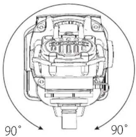
Rotating the Gear Case (Fig. E)
To improve user comfort, the gear case will rotate 90° for cutting operations.
- Remove the four corner screws attaching the gear case to motor housing.
- Without separating the gear case from motor housing, rotate the gear case head to desired position.
NOTE: If the gear case and motor housing become separated by more than 1/8" (3 mm), the tool must be serviced and re-assembled by a DEWALT service center. Failure to have the tool serviced may motor and bearing failure.
- Reinstall screws to attach the gear case to the motor housing. Tighten screws to 12.5 in.-lbs. torque. Overtightening could cause screws to strip.
Guards
CAUTION: Guards must be used with all grinding wheels, cutting wheels, sanding flap discs, wire brushes, and wire wheels. The tool may be used without a guard only when sanding with conventional sanding discs. Refer to Figure A to see guards provided with the unit. Some applications may require purchasing the correct guard from your local dealer or authorized service center.
ENGLISH
NOTE: Edge grinding can be performed with Type 27 wheels designed and specified for this purpose; 1/4" (6.35 mm) thick wheels are designed for surface grinding. A Type 1/41 / Type A guard must be used for any wheel where surface grinding is forbidden. Cutting can also be performed by using a Type 1/41 wheel and a Type 1/41 / Type A guard.
NOTE: See the Accessories Chart to select the proper guard/accessory combination.
Adjusting and Mounting Guard (Fig. F)
WARNING: To reduce the risk of serious personal injury, turn tool off and disconnect battery pack before making any adjustments or removing/installing attachments or accessories. An accidental start-up can cause injury.
- One-touch TM: In this position the engaging face is slanted and will ride over to the next alignment hole 14 when guard is rotated in a clockwise direction (spindle facing user) but self-locks in the counter-clockwise direction.
Mounting Guard (Fig. F)
- With the spindle facing the operator, press and hold the guard release lever 10.
- Align the lugs 15 on the guard with the slots 16 on the gear case cover.
- Push the guard down until the guard lugs engage and rotate them in the groove on the gear case cover. Release the guard release lever.
- To position the guard
One-touch™: Rotate the guard clockwise into the desired working position. Press and hold the guard release lever 10 release lever to rotate the guard in the anti-clockwise direction.
NOTE: The guard body should be positioned between the spindle and the operator to provide maximum operator protection.
The guard release lever should snap into one of the alignment holes 14 on the guard collar. This ensures that the guard is secure.
- To remove the guard, follow steps 1–3 of these instructions in reverse.
Flanges and Wheels
WARNING: To reduce the risk of serious personal injury, turn unit off and remove the battery pack before making any adjustments or removing/installing attachments or accessories. An accidental start-up can cause injury.
Mounting Non-Hubbed Wheels (Fig. A, G)
WARNING: Failure to properly seat the flanges and/or wheel could result in serious injury (or damage to the tool or wheel).
CAUTION: Included flanges must be used with Type 27 compressed center grinding wheels. See the Accessories Chart for more information.
WARNING: Use of a damaged flange or guard or failure to use proper flange and guard can result in
injury due to wheel breakage and wheel contact. See the Accessories Chart for more information.
- Place the tool on a table, guard up.
- Install the backing flange 7 on spindle 5 with the raised center (pilot) facing the wheel. Press the backing flange into place.
- Place wheel 17 against the backing flange, centering the wheel on the raised center (pilot) of the backing flange.
- While depressing the spindle lock button and with the hex depressions facing away from the wheel, thread the locking flange 8 on spindle.
- While depressing the spindle lock button, tighten the locking flange 8 by hand or using the wrench supplied. (Only use a locking flange if it is in perfect condition.) Refer to Accessory Chart to see flange details.
- To remove the wheel, reverse the above procedure.
Mounting Sanding Backing Pads (Fig. A, H)
WARNING: Use only backing pads that are rated for at least equal to the rated speed marked on the tool.
WARNING: Failure to properly seat the clamp nut and/or pad could result in serious injury (or damage to the tool or wheel).
WARNING: Proper guard must be reinstalled for giving wheel, cutting wheel, sanding flap disc, wire brush or wire wheel applications after sanding applications are complete.
NOTE: Use of a guard with sanding discs that use backing pads, often called fiber resin discs, is not required. Since a guard is not required for these accessories, the guard may or may not fit correctly if used.
- Place or appropriately thread backing pad 18 on the spindle.
- Place the sanding disc 19 on the backing pad.
- While depressing spindle lock button 4, thread the sanding clamp nut 21 on spindle, piloting the raised hub on the clamp nut into the center of sanding disc and backing pad.
- Tighten the clamp nut by hand. Then depress the spindle lock button while turning the sanding disc until the sanding disc and clamp nut are snug.
- To remove the wheel, grasp and turn the backing pad and sanding pad while depressing the spindle lock button.
Mounting and Removing Hubbed Wheels (Fig. A)
Hubbed wheels install directly on the spindle with 5/8-11 thread. Thread of accessory must match thread of spindle.
- Remove backing flange by pulling away from tool.
- Thread the wheel on the spindle 5 by hand.
-
Depress the spindle lock button 4 and use a wrench to tighten the hub of the wheel.
-
Reverse the above procedure to remove the wheel.
NOTICE: Failure to properly seat the wheel before turning the tool on may result in damage to the tool or the wheel.
Mounting Wire Cup Brushes and Wire Wheels (Fig. A)
WARNING: Failure to properly seat the brush/wheel could result in serious injury (or damage to the tool or wheel).
CAUTION: To reduce the risk of personal injury, work gloves when handling wire brushes and wheels. They can become sharp.
CAUTION: To reduce the risk of damage to the wheel or brush must not touch guard when
mounted or while in use. Undetectable damage could occur to the accessory, causing wires to fragment from accessory wheel or cup.
Wire cup brushes or wire wheels install directly on the threaded spindle without the use of flanges. Use only wire brushes or wheels provided with a 5/8"-11 threaded hub. These accessories are available at extra cost from your local dealer or authorised service center.
- Place the tool on a table, guard up.
- Thread the wheel on the spindle 5 by hand.
- Depress spindle lock button 4 and use a wrench on the hub of the wire wheel or brush to tighten the wheel.
- To remove the wheel, reverse the above procedure.
NOTICE: To reduce the risk of damage to the tool, properly seat the wheel hub before turning the tool on.
Prior to Operation
• Install the guard and appropriate disc or wheel. Do not use excessively worn discs or wheels.
- Be sure the backing and threaded locking flange are mounted correctly. Follow the instructions given in the Accessories Chart.
- Make sure the disc or wheel rotates in the direction of the arrows on the accessory and the tool.
- Do not use a damaged accessory. Before each use inspect the accessory such as abrasive wheels for chips and cracks, backing pad for cracks, tear or excess wear, wire brush for loose or cracked wires. If power tool or accessory is dropped, inspect for damage or install an undamaged accessory. After inspecting and installing an accessory, position yourself and bystanders away from the plane of the rotating accessory and run the power tool at maximum no-load speed for one minute. Damaged accessories will normally break apart during this test time.
• Install and tighten the auxiliary handle.
OPERATION
WARNING: To reduce the risk of serious personal injury, turn unit off and remove the battery pack before making any adjustments or removing/installing attachments or accessories. An accidental start-up can cause injury.
Installing and Removing the Battery Pack (Fig. J)
WARNING: Ensure the tool/appliance is in the off position before inserting the battery pack.
nOTE: For best results, make sure your battery pack is fully charged.
- To install the battery pack 12 into the tool handle, align the battery pack with the rails inside the tool's handle and slide it into the handle until the battery pack is firmly seated in the tool and ensure that it does not disengage.
- To remove the battery pack from the tool, press the release button 13 and firmly pull the battery pack out of the tool handle. Insert it into the charger as described in the charger section of this manual.
Proper Hand Position (Fig. K)
WARNING: To reduce the risk of serious personal injury, ALWAYS use proper hand position as shown.
WARNING: To reduce the risk of serious personal injury, ALWAYS hold securely in anticipation of a sudden reaction.
Proper hand position requires one hand on the main handle 24 and the other hand on the auxiliary handle 6, as shown in Fig. K.
Switches
CAUTION: Hold the auxiliary handle and body of the tool firmly to maintain control of the tool at start up and during use and until the wheel or accessory stops rotating. Make sure the wheel has come to a complete stop be fore laying the tool down.
NOTE: To reduce unexpected tool movement, do not switch the tool on or off while under load conditions. Allow the grinder to run up to full speed before touching the work surface. Lift the tool from the surface before turning the tool off. Allow the tool to stop rotating before putting it down.
Slider Switch (Fig. A)
DCG409VS
WARNING: Before connecting the tool to a power supply, be sure the slider switch is in the off position. Ensure the slider switch is in the off position after any interruption in power supply to the tool, such as the activation of a ground fault interrupter, throwing of a circuit breaker, accidental unplugging, or power failure. If the slider switch is locked on when the power is connected, the tool will start unexpectedly.
To start the tool, slide the ON/OFF slider switch 2 toward the front of the tool. To stop the tool, release the ON/OFF slider switch.
For continuous operation, slide the switch toward the front of the tool and press the forward part of the switch inward. To stop the tool while operating in continuous mode, press the rear part of the slider switch and release.
Paddle Switch (Fig. A)
DCG416VS
WARNING: Before connecting the tool to a power supply, be sure the paddle switch is in the off position by pressing the rear part of the switch and releasing. Ensure the paddle switch is in the off position as described above after any interruption in power supply to the tool, such as the activation of a ground fault interrupter, throwing of a circuit breaker, accidental unplugging, or power failure. If the paddle switch is locked on when the power is connected, the tool will start unexpectedly.
- To turn the tool on, push the lock-off lever 3 toward the back of the tool, then depress the paddle switch 1. The tool will run while the switch is depressed.
- Turn the tool off by releasing the paddle switch.
Variable Speed Dial (Fig. L)
The variable speed dial 11 offers added tool control and enables the tool to be used at optimum conditions to suit the accessory and material.
- Turn the variable speed dial 11 to the desired level. Turn the dial upward for higher speed and downward for lower speed.
Spindle Lock (Fig. M)
The spindle lock button 4 is provided to prevent the spindle from rotating when installing or removing wheels. Operate the spindle lock only when the tool is turned off, the battery is removed and has come to a complete stop.
NOTICE: To reduce the risk of damage to the tool, do not engage the spindle lock while the tool is operating. Damage to the tool will result and attached accessory may spin off possibly resulting in injury.
To engage the lock, depress the spindle lock button and rotate the spindle until you are unable to rotate the spindle further.
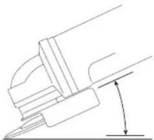
Surface Grinding, Sanding and Wire Brushing (Fig. N)
CAUTION: Always use the correct guard per the instructions in this manual.
To perform work on the surface of a workpiece:
- Allow the tool to reach full speed before touching the tool to the work surface.
- Apply minimum pressure to the work surface, allowing the tool to operate at high speed. Material removal rate is greatest when the tool operates at high speed.
- Maintain an appropriate angle between the tool and work surface. Refer to the chart according to particular function.
| Function Angle | ∠ |
| Grinding 20°-30° | |
| Sanding with Flap Disc 5°-10° | |
| Sanding with Backing Pad 5°-15° | |
| Wire Brushing 5°-10° |
-
Maintain contact between the edge of the wheel and the work surface.
-
If grinding, sanding with flap discs, or wire brushing, move the tool continuously in a forward and back motion to avoid creating gouges in the work surface.
- If sanding with a backing pad, move the tool constantly in a straight line to prevent burning and swirling of work surface.
NOTE: Allowing the tool to rest on the work surface without moving will damage the workpiece.
- Remove the tool from work surface before turning tool off. Allow the tool to stop rotating before laying it down.
CAUTION: Use extra care when working over an edge, as a sudden sharp movement of grinder may be experienced.
Precautions To Take When Working on a Painted Workpiece
- Sanding or wire brushing of lead based paint is NOT RECOMMENDED due to the difficulty of controlling the contaminated dust. The greatest danger of lead poisoning is to children and pregnant women.
- Since it is difficult to identify whether or not a paint contains lead without a chemical analysis, we recommend the following precautions when sanding any paint:
Personal Safety
- No children or pregnant women should enter the work area where the paint sanding or wire brushing is being done until all clean up is completed.
- A dust mask or respirator should be worn by all persons entering the work area. The filter should be replaced daily or whenever the wearer has difficulty breathing.
NOTE: Only those dust masks suitable for working with lead paint dust and fumes should be used. Ordinary painting masks do not offer this protection. See your local hardware dealer for the proper approved mask. - NO EATING, DRINKING or SMOKING should be done in the work area to prevent ingesting contaminated paint particles. Workers should wash and clean up BEFORE eating, drinking or smoking. Articles of food, drink, or smoking should not be left in the work area where dust would settle on them.
Environmental Safety
- Paint should be removed in such a manner as to minimize the amount of dust generated.
- Areas where paint removal is occurring should be sealed with plastic sheeting of 4 mils thickness.
- Sanding should be done in a manner to reduce tracking of paint dust outside the work area.
Cleaning and Disposal
- All surfaces in the work area should be vacuumed and thoroughly cleaned daily for the duration of the sanding project. Vacuum filter bags should be changed frequently.
- Plastic drop cloths should be gathered up and disposed of along with any dust chips or other removal debris.
They should be placed in sealed refuse receptacles and disposed of through regular trash pick-up procedures. During clean up, children and pregnant women should be kept away from the immediate work area.
- All toys, washable furniture and utensils used by children should be washed thoroughly before being used again.
Edge Grinding and Cutting (Fig. 0)
WARNING: Do not use edge grinding/cutting wheels for surface grinding applications because these wheels are not designed for side pressures encountered with surface grinding. Wheel breakage and injury may result.
CAUTION: Wheels used for edge grinding and cutting may break or kick back if they bend or twist while the tool is being used. In all edge grinding/cutting operations, the open side of the guard must be positioned away from the operator.
NOTICE: Edge grinding/cutting with a Type 27 wheel must be limited to shallow cutting and notching—less than 1/2" (13 mm) in depth when the wheel is new. Reduce the depth of cutting/notching equal to the reduction of the wheel radius as it wears down. Refer to the Accessories Chart for more information. Edge grinding/cutting with a Type 41 wheel requires usage of a Type 1/41 / Type A guard.
- Allow the tool to reach full speed before touching the tool to the work surface.
- Apply minimum pressure to the work surface, allowing the tool to operate at high speed. Grinding/cutting rate is greatest when the tool operates at high speed.
- Position yourself so that the open-underside of the wheel is facing away from you.
- Once a cut is begun and a notch is established in the workpiece, do not change the angle of the cut. Changing the angle will cause the wheel to bend and may cause wheel breakage. Edge grinding wheels are not designed to withstand side pressures caused by bending.
- Remove the tool from the work surface before turning the tool off. Allow the tool to stop rotating before laying it down.
MAINTENANCE
WARNING: To reduce the risk of serious personal injury, turn unit off and remove the battery pack before making any adjustments or removing/installing attachments or accessories. An accidental start-up can cause injury.
Your DEWALT power tool has been designed to operate over a long period of time with a minimum of maintenance. Continuous satisfactory operation depends upon proper tool care and regular cleaning.
Cleaning
WARNING: Blow dirt and dust out of all air vents with dry air at least once a week. To minimize the risk of eye injury, always wear ANSI Z87.1 approved eye protection when performing this procedure.
WARNING: Never use solvents or other harsh chemicals for cleaning the non-metallic parts of the tool. These chemicals may weaken the plastic materials used in these parts. Use a cloth dampened only with water and mild soap. Never let any liquid get inside the tool; never immerse any part of the tool into a liquid.
Accessories
WARNING: Since accessories, other than those offered by DEWALT, have not been tested with this product, use of such accessories with this product could be hazardous. To reduce the risk of injury, only DEWALT recommended accessories should be used with this product.
WARNING: Do not use a bonded abrasive wheel that is past its expiration (EXP) date as marked near center of wheel, if provided. Expired wheels are more likely to burst and cause serious injury. Store bonded abrasive wheels in dry location without temperature or humidity extremes. Destroy expired or damaged wheels so they cannot be used.
Recommended accessories for use with your product are available at extra cost from your local dealer or authorized service center. If you need assistance in locating any accessory, please contact DEWALT call 1-800-4-DEWALT (1-800-433-9258) or visit our website: www.dewalt.com.
Tool Connect™ Chip (Fig. I)
WARNING: To reduce the risk of serious personal injury, turn unit off and remove the battery pack before making any adjustments or removing/installing attachments or accessories. An accidental start-up can cause injury.
Your tool is Tool Connect™ Chip ready and has a location for installation of a Tool Connect™ Chip.
Tool Connect™ Chip is an optional application for your smart device (such as a smart phone or tablet) that connects the device to utilize the mobile application for inventory management functions.
Refer to Tool Connect™ Chip Instruction Sheet for more information.
Installing the Tool Connect™ Chip
- Remove the retaining screws 21 that hold the Tool Connect™ Chip protective cover 22 into the tool.
- Remove the protective cover and insert the Tool Connect™ Chip into the empty pocket 23.
- Ensure that the Tool Connect™ Chip is flush with the housing. Secure it with the retaining screws and tighten the screws.
- Refer to Tool Connect™ Chip Instruction Sheet for further instructions.
Repairs
The charger and batteries are not serviceable. There are no serviceable parts inside the charger or battery pack.
WARNING: To assure product SAFETY and RACEABILITY, repairs, maintenance and adjustment (including brush inspection and replacement, when
applicable) should be performed by a DEWALT factory service center or a DEWALT authorized service center. Always use identical replacement parts.
Register Online
Thank you for your purchase. Register your product now for:
- WARRANTY SERVICE: Registering your product will help you obtain more efficient warranty service in case there is a problem with your product.
- CONFIRMATION OF OWNERSHIP: In case of an insurance loss, such as fire, flood or theft, your registration of ownership will serve as your proof of purchase.
• FOR YOUR SAFETY: Registering your product will allow us to contact you in the unlikely event a safety notification is required under the Federal Consumer Safety Act.
• Register online at www.dewalt.com.
Three Year Limited Warranty
For warranty terms, go to https://www.dewalt.com/Legal/Warranty/3-Year-Limited-Warranty.
To request a written copy of the warranty terms, contact: Customer Service at DEWALT Industrial Tool Co., 701 East Joppa Road, Towson, MD 21286 or call 1-800-4-DEWALT (1-800-433-9258).
LATIN AMERICA: This warranty does not apply to products sold in Latin America. For products sold in Latin America, see country specific warranty information contained in the packaging, call the local company or see website for warranty information.
FREE WARNING LABEL REPLACEMENT: If your warning labels become illegible or are missing, call 1-800-4-DeWALT (1-800-433-9258) for a free replacement.
ACCESSORIES CHART
| Approved wheels for use with DCG409VS, DCG416VS | |
| Type 1 / T1 / 41 / T41 |  |
| Type 27 / T27 |  |
| Type 28 / T28† |  |
| Type 29 / T29 | 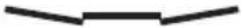 |
| Non-approved wheels for DCG409VS, DCG416VS | |
| Type 11 / T11 |  |
| 5" (125 mm) Grinding Wheels | |
| Type 27 guardType B guard |  |
| Backing flange |  |
| Type 27Depressed centerwheel | 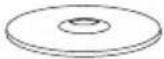 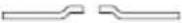 |
| Locking flange |  |
| 5" (125 mm) Grinding Wheels | |
| Type 27 guardType B guard | |
| Type 27 hubbedwheel | |
| 5" (125 mm) Sanding Flap Discs | |
| Type 27 guardType B guard | |
| Backing flange | |
| Non-hubbed sandingflap disc | |
| Locking flange | |
| 5" (125 mm) Sanding Flap Discs | |
| Type 27 guardType B guard | |
| Hubbed sandingflap disc | |
5" (125 mm) Grinding Wheels
| Type 27 guardType B guard |  |
| Type 27 hubbedwheel | 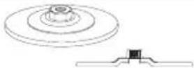 |
5" (125 mm) Sanding Flap Discs
| Type 27 guardType B guard | 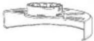 |
| Backing flange |  |
| Non-hubbed sanding flap disc | 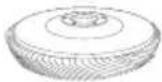 |
| Locking flange |  |
5" (125 mm) Sanding Flap Discs
| Type 27 guardType B guard | 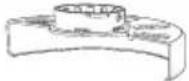 |
| Hubbed sandingflap disc | 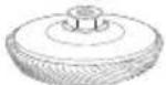 |
| 5" (125 mm) Cutting Wheels | |
| Type 1/41 guard**Type A guard** | 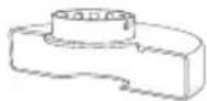 |
| Backing flange | |
| Type 27/42 depressedcenter wheel,cutting only | 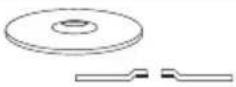 |
| Locking flange |  |
| 5" (125 mm) Cutting Wheels | |
| Type 1/41 guard**Type A guard** | 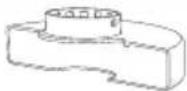 |
| Backing flange |  |
| Type 1/41 abrasivecutting wheel |  |
| Locking flange |  |
| 5" (125 mm) Cutting Wheels | |
| Type 1/41 guard**Type A guard** | 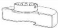 |
| Backing flange |  |
| Diamond cuttingwheel | 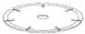 |
| Locking flange |  |
| Wire Wheels | |
| Type 27 guardType B guard | 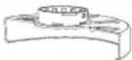 |
| 3-4" (76.2-100 mm)wire cup brush | 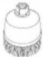 |
| Wire Wheels | |
| Type 27 guardType B guard | 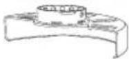 |
| 4" (100 mm)wire wheel |  |
| 5" (125 mm) Sanding Discs | |
| Rubber backing pad | 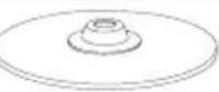 |
| Sanding disc |  |
| Clamp nut |  |
Type 1/41 / Type A guards are intended for use while Type 1/41 cutting wheels and Type 27 wheels marked for cutting only. Grinding with wheels other than Type 27 and Type 29 require different accessory guards. Always use the smallest proper guard possible that does not contact the accessory.
** NOTE: A Type 1/41 / Type A guard is available at extra cost from your local dealer or authorized service center.
portezdes protections auditives
natural_image
Technical line drawing of a mechanical device with no visible text or symbolsnatural_image
Technical line drawing of a mechanical component with no visible text or symbolsEje Central Lázaro Cárdenas No. 18 - Local (55) 5588 9377 D, Col. Obrera
MERIDA, YUC
Calle 63 #459-A - Col. Centro (999) 928 5038
MONTERREY, N.L.
Av. Francisco I. Madero 831 Poniente - Col. (818) 375 23 13 Centro
PUEBLA, PUE
17 Norte #205 - Col. Centro (222) 246 3714
QUERETARO, QRO
Av. San Roque 274 - Col. San Gregorio (442) 2 17 63 14
SAN LUIS POTOSI, SLP
Col. Santa Fe Alvaro Obregon,
Ciudad de Mexico, Mexico.
C.P 01210
TEL(52) 55 53267100
R.F.C.BDE8106261W7
Registro en Línea
www.dewalt.com/Legal/Warranty/3-Year-Limited-Warranty.
NOTE: The Bluetooth® word mark and logos are registered trademarks owned by the Bluetooth®, SIG, Inc. and any use of such marks by DEWALT is under license. Other trademarks and trade names are those of their respective owners.
VING: Use of any other battery packs may create a risk of injury and fire.
