
FinishControl 6500 TS - Paint spray WAGNER - Free user manual and instructions
Find the device manual for free FinishControl 6500 TS WAGNER in PDF.


| Product type | XVLP (Extra Volume Low Pressure) spray jet |
| Brand and model | Wagner FinishControl 6500 TS |
| Power supply | 230 V ~ 50 Hz |
| Power consumption | 1900 W |
| Spraying power | 300 W |
| Weight (turbine, hose, gun) | 9 kg |
| Air hose length | 5 m |
| Power cord length | 4 m |
| Bucket capacity (TempCup) | 600 ml |
| Sound pressure level | 84 dB(A) (uncertainty K=4 dB) |
| Sound power level | 97 dB(A) (uncertainty K=4 dB) |
| Vibration level | <2.5 m/s² (uncertainty K=1.5 m/s²) |
| Protection class | I |
| Main functions | Product heating (30 °C or 50 °C), automatic cleaning, Click&Paint system |
| Compatible products | Solvent-based and water-based paints, glazes, varnishes, impregnations (non-abrasive) |
| Available removable facades | TempSpray (red), FineSpray (brown), WallSpray (white), StandardSpray (yellow) |
| Air filter | Replaceable, check before each use |
| Maintenance | Immediate cleaning of bucket and nozzle after use; do not immerse the gun |
| Safety | Do not use in ATEX zones; wear goggles and mask; maintain a distance of 3 m between turbine and object |
| Warranty | 36 months (professional use) / 12 months (intensive use) with possible extension upon registration |
Frequently Asked Questions - FinishControl 6500 TS WAGNER
User questions about FinishControl 6500 TS WAGNER
0 question about this device. Answer the ones you know or ask your own.
Ask a new question about this device
Download the instructions for your Paint spray in PDF format for free! Find your manual FinishControl 6500 TS - WAGNER and take your electronic device back in hand. On this page are published all the documents necessary for the use of your device. FinishControl 6500 TS by WAGNER.
USER MANUAL FinishControl 6500 TS WAGNER
natural_image
Technical line drawing of a mechanical assembly with labeled parts (no text or symbols present)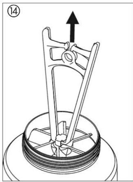
natural_image
Mechanical assembly diagram showing a rotating component with a central shaft and upward arrow indicator (no text or symbols)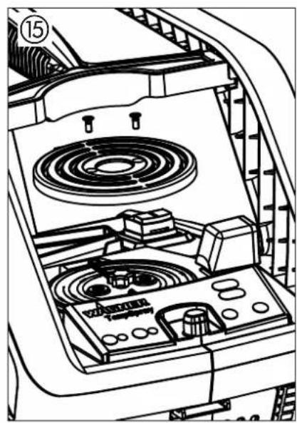
natural_image
Technical line drawing of a mechanical device with internal components and no visible text or symbols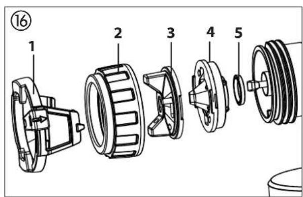
natural_image
Mechanical diagram of a pulley and lever assembly (no text or labels)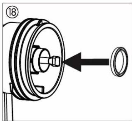
natural_image
Mechanical assembly diagram showing a pulley and housing with an arrow indicating direction (no text or symbols)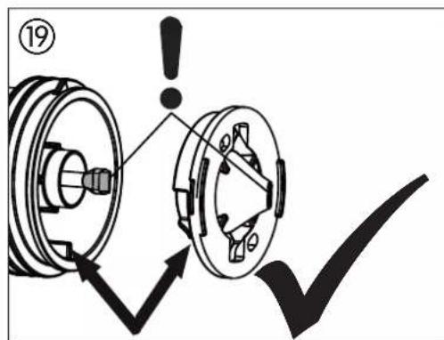
natural_image
Mechanical component diagram showing two pulleys crossed by a diagonal line (no text or symbols)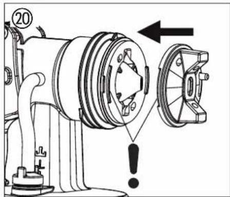
natural_image
Technical diagram of a mechanical assembly showing two components with a directional arrow indicating rotation (no text or symbols present)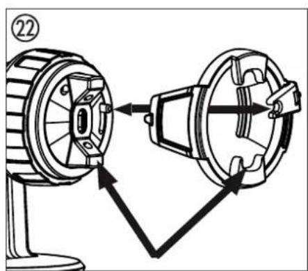
natural_image
Technical line drawing of a mechanical device with two views showing internal components (no text or symbols)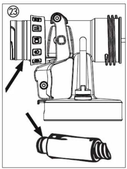
Inhaltsverzeichnis
Division Professional Finishing
Otto Lilienthal Strasse 18
88677 Markdorf
Translation of the original operating instructions
Contents
1 SAFETY REGULATIONS ____ 17
2 EXPLANATORY DIAGRAM 20
3 SETTING AND DISPLAYS ON THE CONTROL PANEL ____ 20
4 THE WAGNER CLICK&PAINT SYSTEM ____ 21
4.1 Disassembly of the spray gun ____ 21
5 TECHNICAL DATA 21
6 INTRODUCTION TO SPRAYING USING THE XVLP PROCEDURE 21
7 COATING MATERIAL 21
7.1 Coating Materials Suitable for Use ____ 21
7.2 Coating Materials Not Suitable for Use ____ 21
7.3 Coating materials that can only be processed with relevant spray attachment (accessories) ____ 22
7.4 Preparing the coating material 22
8 SETTING THE SPRAY GUN 22
8.1 Setting the required spray pattern ____ 22
8.2 Setting the amount of material 22
8.3 Setting the amount of air 22
8.4 Align the feed tube 22
13 TAKING OUT OF OPERATION AND CLEANING _ 24
13.1 Assembly 24
14 MAINTENANCE 25
14.1 Air filter 25
14.2 Air relief valve 25
15 CORRECTION OF MALFUNCTIONS 26
16 ACCESSORIES AND SPARE PARTS 27
16.1 Accessories 27
16.2 Spare parts FinishControl 28
16.3 Spare Parts TempSpray spray attachment ____ 28
Testing of the unit 29
Note on disposal 29
Important information on product liability ____ 29
Guarantee declaration 29
CE - declaration 136
European service network 138
Explanation of symbols used
 | This symbol indicates a potential danger for you or for the device.Under this symbol you can find important information on how to avoid injuries and damage to the device. |
 | Indicates tips for use and other particularly useful information. |
 | Wide spray jet setting |
 | Narrow spray jet setting |
 | Wear protective gloves. |
 | Attention! Hot surface |
1 SAFETY REGULATIONS
All local safety regulations in force must be observed.
Read the operating instructions carefully and follow the instructions laid down in them in order to avoid risks.
1. Safety at the workplace
Keep your workplace clean and well lit. a)
Disorder or unlit workplaces may result in accidents.
Never use the tool in hazardous areas that contain b) flammable liquids, gases or dusts. Power tools generate sparks that can ignite the dust or vapors.
Keep children and other persons away when using c) the power tool. You can lose control of the tool if you are distracted.
2. Electrical Safety
The tool plug must fit into the socket. The plug may a) not be modified in any form. Do not use adaptor plugs together with protective-earthed tools.
Unmodified plugs and suitable sockets reduce the risk of an electric shock.
Avoid physical contact with earthed surfaces such b) as pipes, heating elements, stoves and refrigerators.
The risk through electric shock increases if your body is earthed.
Keep the equipment away from rain and moisture. c)
The risk of an electric shock increases if water penetrates electrical equipment.
Do not misuse the mains lead by carrying the tool d) by the lead, hanging it from the lead or by pulling on the lead to remove the plug. Keep the lead away from heat, oil, sharp edges or moving tool parts.
Damaged or twisted leads increase the risk of an electric shock.
e) If you work outdoors with a power tool, only use extension cables suitable for outdoor use. The use of an extension lead that is suitable for outdoors reduces the risk of an electric shock.
f) If you cannot avoid using the tool in a damp environment, use a residual current operated circuit-breaker. Using a residual current operated circuit-breaker avoids the risk of electric shock.
3. Safety of Persons
a) Be attentive. Pay attention to what you are doing and work sensibly with a power tool. Do not use the tool if you are tired or under the influence of drugs, alcohol or medication. Just a moment of inattentiveness while using the tool can lead to serious injuries.
Wear personal safety equipment and always wear b) safety goggles. Wearing personal protective equipment, such as dust mask, non-slip safety shoes, safety helm or ear protection, depending on the type of power tools, reduces the risk of injury.
c) Avoid accidental starting-up. Ensure that the switch is in the "OFF" position before inserting the plug into the socket. Accidents can occur if you carry the power tool while your finger is on the switch or if you connect the power tool to the power supply which it is on.
d) Remove setting tools or wrenches before switching on the power tool. A tool or wrench that is in a rotating tool part can lead to injuries.
e) Avoid an unnatural posture. This ensures that you can control the tool better in unexpected situations.
f) Wear suitable clothing. Do not wear wide clothing or jewelry. Keep your hair, clothes and gloves away from moving parts. Loose clothing, jewelry or long hair can be caught in moving parts.
g) This appliance is not intended for use by persons (including children) with reduced physical, sensory or mental capabilities, or lack of experience and knowledge, unless they have been given supervision or instruction concerning use of the appliance by a person responsible for their safety.
Children should be supervised to ensure that they do not play with the appliance.
4. Careful Handling and Use of Power Tools
a) Do not overload the tool. Use the power tool designed for the work that you are doing. You work better and safer in the specified performance range if you use the suitable power tool.
b) Do not use power tools whose switch is defective. A power tool that cannot be switched on or off is dangerous and has to be repaired.
c) Remove the plug from the socket before carrying out tool settings, changing accessories or putting the tool away. This precautionary measure prevents unintentional starting of the tool.
d) Store unused power tools so that they are inaccessible to children. Do not let persons use the
tool who are not familiar with it or who have not read these instructions. Power tools are dangerous when they are used by inexperienced persons.
Take proper care of your tools. Check whether the e) moving parts function trouble-free and do not jam, whether parts are broken or damaged so that the tool function is impaired. Have damaged parts repaired before using the tool. Many accidents have their origin in power tools that have been maintained badly.
Use the power tool, accessories, insert tools, etc. in f) accordance with these instructions and in a fashion specified for this special tool type. Take the working conditions and the activity to be carried out into consideration. The use of power tools for purposes other than the intended ones can lead to dangerous situations.
5. Service
Have your tool repaired only by qualified specialist a) personnel and only with original spare parts. This ensures that the tool safety is maintained.
If the supply cord is damaged, it must be replaced b) by the manufacturer or it's service agent or a similarly qualified person in order to avoid a safety hazard.
Safety instructions for colour application devices
1. Risks of Fire and Explosion
Combustible gases develop in the work area when spraying coating substances and due to the autonomous formation of coating substances and solvent vapors (danger zone).
Risk of fire and explosion due to ignition sources in this danger zone.
The electrically operated spray device contains potential ignition sources (spark formation when switching the motor on and off, when inserting and removing the power plug, due to potential static electricity at the spray gun)
-> Device must not be used at operating sites that fall under the explosion protection ordinance.
-> Basic unit and mains connection must be located outside the danger zone.
-> Do not use combustible coating substances and cleaning agents -> observe product data sheets!
->Always seal paint or solvent containers tightly in the vicinity of the device.
-> No ignition sources such as open fire, lit tobacco products, glowing wires, hot surfaces, sparks e.g. due to angle grinders etc. must be present.
-> When cleaning the device with solvent do not spray into a container with a small opening (bung hole). Danger due to formation of an explosive gas/air mixture.
The container into which you are spraying must be earthed.
2. Warning: Danger of injury!
Never point spray gun at yourself, other persons or animals.
3. Wear breathing equipment when spraying.
The user should be supplied with a breathing mask. In order to avoid occupational diseases, the working instructions provided by the manufacturer of the materials, solvents and cleaning agents used must be complied with during preparation, working with and cleaning the equipment. Protective clothing, gloves and, if necessary, protective skin cream is required to protect the skin.
-
Warning: When working with the paint spraying system, both indoors and outdoors, care should be taken that no solvent vapours are driven to the motor-operated blower or that no solvent containing vapours form in the area around the paint spraying system. Place the motor-operated blower on the opposite side to the object to be sprayed. When working outdoors take wind direction into account. When working in closed places a sufficient ventilation must be ensured to remove the solvent vapours. The distance from the motor – operated blower to the object to be sprayed must be at least 3 m.
-
Warning: The device is not splash proof. It should not be used, neither outdoors in the rain nor be sprayed with water nor immersed in liquid. Do not use the device in damp or wet environments.
6. Warning: risk of short circuit!
Keep heating station and contacts on the underside of the container away from liquids and dirt. Do not use any containers with damaged bases.
7. Warning: risk of electric shock!
Do not block the two slides next to the heating station.
- The sliders must always be able to move freely. Clean whenever necessary.
The units may only be used with a functional valve. If 9. paints rises in the ventilating hose (Fig. 1, item 18) do not operate the unit further! Dismantle and clean the ventilating hose, valve and diaphragm and replace the diaphragm if necessary.
Do not lay the filled spray gun down. 10.
Extraction systems should be installed on-site according 11. to the local regulations.
The object to be coated must be earthed. 12.
Caution against dangers that can arise from the sprayed 13. substance and observe the text and information on the containers or the specifications given by the substance manufacturer.
Do not spray any liquid of unknown hazard potential.14.
Warning: risk of injury from mixer! The heating and 15. cleaning procedures may only be carried out when the container is closed.
- Do not start the heating process until the mixer has been mounted. If the mixer is not in place, the paint will harden in the container.
Before dismounting the spray attachment, relieve 17. pressure by opening the container.
Before working on the device, remove the power plug 18. from the socket.
Work or repairs on the electrical equipment should only 19. be carried out by a professional electrician, even if there are instructions regarding such work in the operating instructions. No liability will be accepted for improper installation.
- Do not sit or stand on the device. Danger of tilting/breaking!
2 eXPIAnAtory dIAgrAM (flg. 1)
POS. DESIGNATION
| 1 Nozzle |
| 2 Air cap |
| 3 Spray jet width adjusting lever (shaping air) |
| 4 Spray jet level adjusting ring (vertical/horizontal) |
| 5 Union nut |
| 6 Spray attachment complete |
| 7 Material volume regulation |
| 8 Gun handle |
| 9 Air volume control |
| 10 Air hose |
| 11 Click&Paint catch |
| 12 Trigger (actuates turbine starting switch → material is conveyed) |
| 13 Container (TempCup) |
| 14 Mixer |
| 15 Suction tube |
| 16 Container seal |
| 17 Valve |
POS. DESIGNATION
| 18 Ventilating hose |
| 19 Carry handle |
| 20 Tool to change mixer |
| 21 ON/OFF switch (l = ON, 0 = OFF) |
| 22 Heating station |
| 23 Control panel |
| 24 Gun mounting for park position |
| 25 Air filter cover |
| 26 Air filter |
| 27 Power cable |
| 28 Air hose connection |
| 29 Cleaning brush |
| 30 Fine feed tube filter (red)Coarse feed tube filter (white) |
| 31 Funnel (3 pcs.) |
| 32 Air hose fixing straps (2 pcs.) |
3 Setting And dISPIAyS on the control PAnel (flg. 2)
| A „30°C” button Setting to warm the paint to approx. 30°C (depending on the paint you are using).Standard setting when switching on the device | |
| B „50°C” button Setting to warm the paint to approx. 50°C (depending on the paint you are using). | |
| C „Heat” button Starts the heating process | |
| D „Clean” button Starts the cleaning process | |
| E Control lamp (yellow) Indicates which temperature is selectedWhen both control lamps are flashing alternately, a function test is currently being run.When both control lamps are flashing at the same time, an error has occurred (information about the type of error and how to rectify it can be found in the chapter, „Correction of Malfunctions“) | |
| F Control lamp „Spray/clean“(green) | This lights up when the paint has reached the desired temperatureIt remains lit during the cleaning process |
| G Control lamp „Heating“ (red) It remains lit while the paint is being heated | |

Keep any button pressed for about 3 seconds to stop the heating or cleaning process
4 THE WAGNER CLICK&PAINT SYSTEM
With the Wagner Click&Paint System, the front part of the gun (spray attachment) can be replaced quickly and easily.
This enables a rapid material change without cleaning, and ensures that the right tool is available for every material and application.
The following spray attachments are available:
| Spray attachment Area of application | |
| TempSpray (red)Order No. 2321 878 | Spray attachment with slot nozzle and heated container (600 ml).The raised temperature enables highly viscose paints to be used. |
| FineSpray (brown)Order No. 2321 877 | Spray attachment with round nozzle and 1000 ml stainless steel container. Ideal for low-viscosity paints and glazes. |
| WallSpray (white)Order No. 2321 880 | Dispersion spray attachment with slit nozzle and 1400 ml plastic container. Designed for processing dispersions. |
4.1 DISASSEMBLY OF THE SPRAY GUN
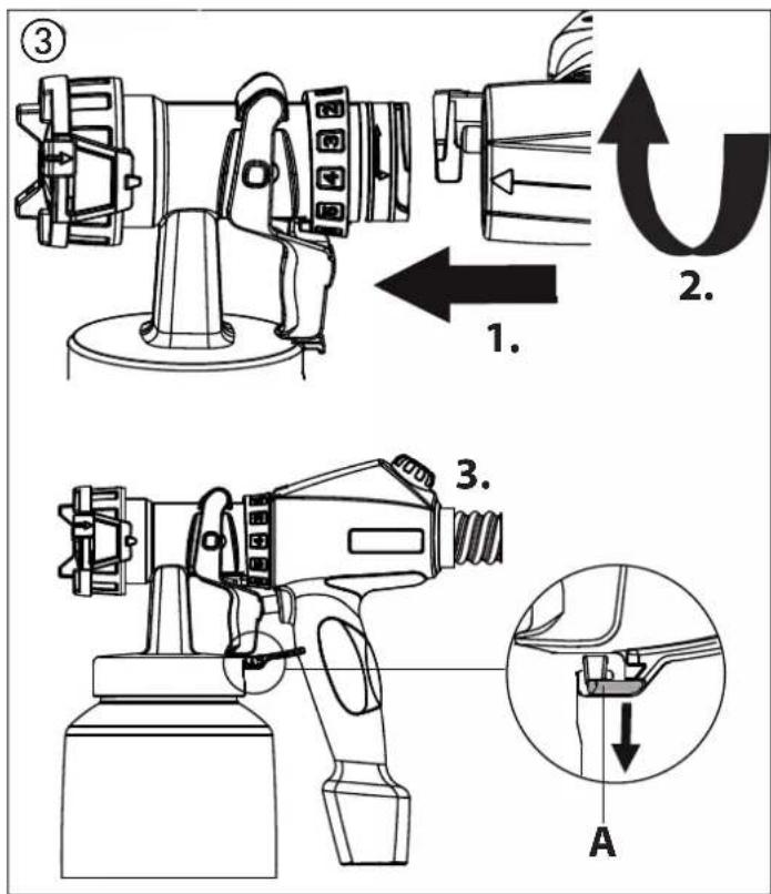
For assembly, insert the spray attachment into the gun handle so that the two arrows point at each other. Turn the gun handle 90^ in the arrow direction until it audibly engages. (Fig. 3) To remove the spray attachment, push the catch (Fig. 3, A) beneath the trigger down and turn the spray attachment by 90^ .
5 TECHNICAL DATA
| Voltage: 230 V~, 50 Hz | |
| Power consumption: 1900 W | |
| Atomizing output: 300 W | |
| Container volume: 600 ml | |
| Air hose: 5 m | |
| Power cable: 4 m | |
| Protection class: | I |
| Sound pressure level:*Uncertainty K: | 84 dB (A)4 dB (A) |
| Sound pressure output:*Uncertainty K: | 97 dB (A)4 dB (A) |
| Oscillation level:Uncertainty K: | <2.5 m/s ^2 1.5 m/s ^2 |
| Weight (motor-operated blower,air hose and spray gun): | 9 kg |
* The acoustic emission value was ascertained in accordance with EN 50144-2-7:2000
6 INTRODUCTION TO SPRAYING USING THE XVLP PROCEDURE
XVLP (Extra Volume Low Pressure) is a low pressure spraying technique, which works with a high volume of air and a low air pressure. The greatest advantage of this spraying technique is the low paint mist formation. This reduces the amount required to cover the object to a minimum.
As opposed to conventional application of coatings, this method achieves a highly economical and perfect surface quality and is, at the same time, environmentally friendly.
Function description
The paint spraying system consists of a motor-operated turbo-blower, which provides the spray gun with atomisation air through an air hose.
In the spray gun, a part of the atomisation air is used to pressurise the container. This pressure causes the coating material to be fed through the uptake pipe to the nozzle where it is atomised by the rest of the atomisation air.
All settings necessary for operation (e.g. material volume) can be conveniently made, directly on the gun.
Thanks to the heating station, which is integrated into the basic device, the paint can be heated up in the supplied Temp-Spray spray attachment.
7 COATING MATERIAL
7.1 COATING MATERIALS SUITABLE FOR USE
Solvent-based and water-soluble lacquer paints Mordants, glazes, impregnations, oils, clear varnishes, synthetic enamels, coloured paints, alkyd resin varnishes, primers, radiator paints, hammer effect enamels, anti-rust paints, special-effect paints, textured paints
7.2 COATING MATERIALS NOT SUITABLE FOR USE
Materials that contain highly abrasive components, facade paint, caustic solutions and acidic coating substances.
Flammable materials.
7.3 COATING MATERIALS THAT CAN ONLY BE PROCESSED WITH RELEVANT SPRAY ATTACHMENT (ACCESSORIES)
Interior wall paint (dispersions and latex paint)
7.4 PREPARING THE COATING MATERIAL

Observe the manufacturer's instructions for the use of the coating material on the paint tin or on the technical instruction sheet (particularly information about the flash point in flammable materials and the maximum permitted temperature)!

If necessary, you can use the FinishControl 6500 TS to mix the paint. Do this by putting the closed TempSpray attachment on the heating station and press the "Clean" button.
Coating material purity:
An absolute pre-condition for the trouble-free operation of the fine-spray system is that the coating material is uncontaminated. If you have doubts as to the purity of the coating material, we recommend that you first filter it through a fine sieve.
Processing the coating material with the TempSpray spray attachment (red)
| Coating Material Processing Comments | ||
| Solvent-based lacquer paints | observe manufacturer's instructions | |
| Water-soluble lacquer paints | observe manufacturer's instructions | |
| Mordants, glazes, impregnations, oils | undiluted FineSpray | spray attachment (brown) recommended |
| Clear varnishes, synthetic enamels, coloured paints, alkyd resin varnishes | observe manufacturer's instructions | |
| Primers, radiator paints, hammer effect enamels | observe manufacturer's instructions | |
| Anti-rust paints, special-effect paints | observe manufacturer's instructions | |
| Multicolor paints, textured paints | observe manufacturer's instructions | WallSpray spray attachment (white) recommended |
8 SETTING THE SPRAY GUN
8.1 SETTING THE REQUIRED SPRAY PATTERN

Attention: Never pull trigger while adjusting the air cap settings.
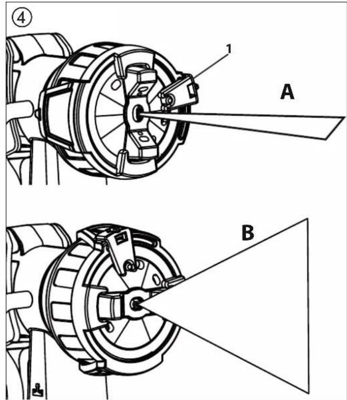
The alignment of the spray jet can be determined by turning the black adjusting ring (Fig. 4, 1).
A horizontal flat jet
→ for vertical surfaces
B vertical flat jet
→ for horizontal surfaces
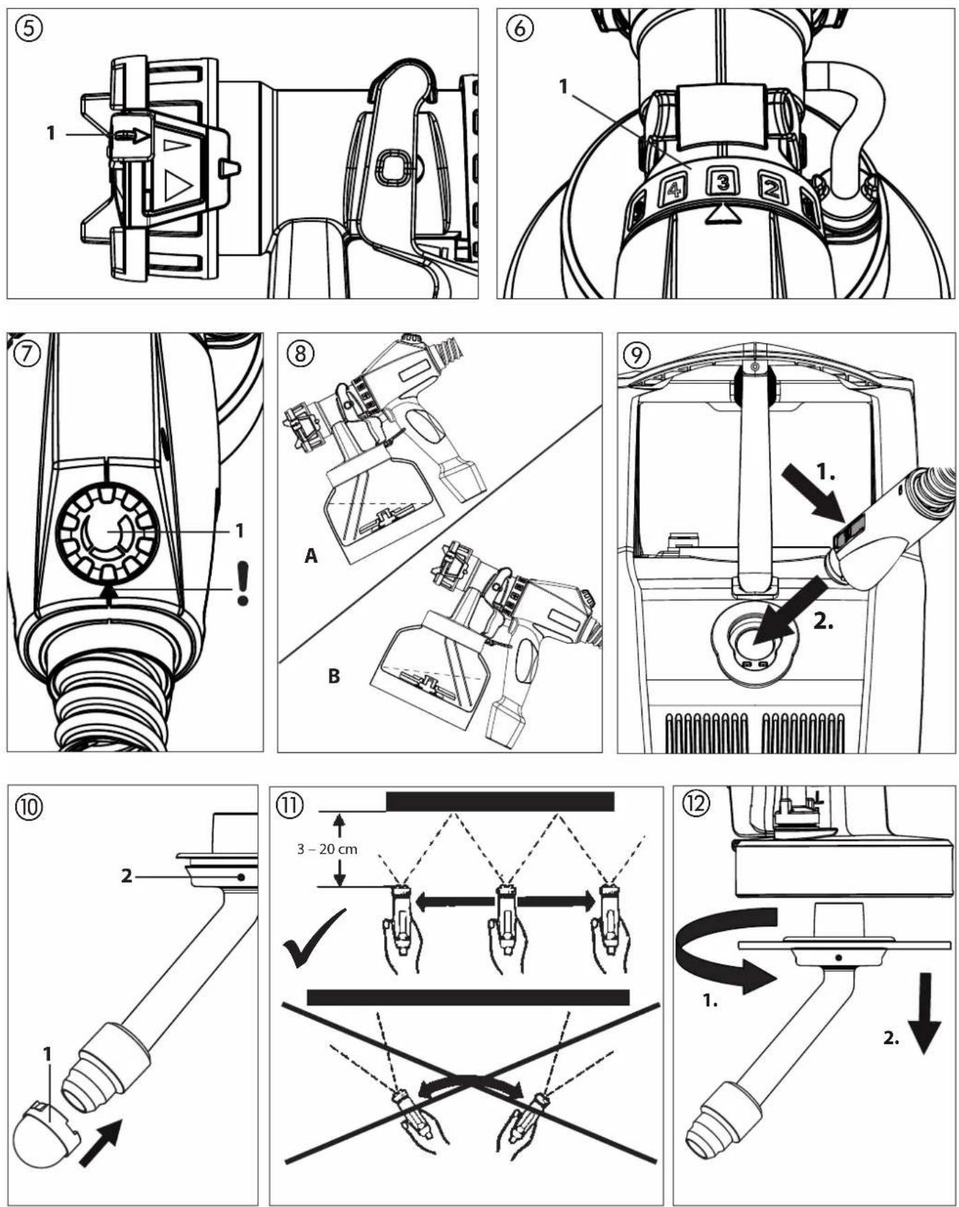
It is also possible to switch between a wide ▶) and a compact (▶) spray jet with the adjusting lever (Fig. 5, 1).
8.2 SETTING THE AMOUNT OF MATERIAL (FIG. 6)
The material volume can be adjusted incrementally from 1 (minimum) to 12 (maximum) by turning the material volume control (Fig. 6, 1).
8.3 SETTING THE AMOUNT OF AIR (FIG. 7)
Turn the air volume control (Fig. 7, 1) clockwise to increase the air volume or anti-clockwise to reduce the air volume (note arrow on body of gun).

The correct setting of air and material volume is crucial for atomisation and paint mist formation.
8.4 ALIGN THE FEED TUBE
If the feed tube is positioned correctly, the container contents can be sprayed without almost any residue.
When working on lying objects:
Turn the feed tube forwards. (Fig. 8 A)
Spraying work when working on overhead objects:
Turn the feed tube rearwards. (Fig. 8 B)
Before connecting to the mains supply make sure that the mains voltage corresponds to the operating voltage on the rating plate. The unit must be connected with a properly earthed shockproof socket.
- Squeeze the side clips together and insert the air hose onto the basic unit. (Fig. 9)
Unscrew the container from the spray attachment.2. Pour in the prepared coating material.3.

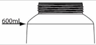
Fill the container with maximum 600 ml.
- Fit the appropriate filter to the feed tube depending on the coating material used (Fig. 10, 1)
Low-viscosity coating materials → Fine filter (red)
Viscous coating materials → Coarse filter (white)

WARNING: Check that the mixer is mounted in the container. If the mixer is not in place the paint can harden in the container during the heating process.
- Screw the container firmly onto the spray attachment.
Plug in the power cable.6.
Switch on the main switch at the device. 7.

The paint can only be heated on the heating station with the TempSpray attachment. If you do not want to heat the paint, or if you do not want to use the TempSpray attachment, skip sections 8-12.

Warning: risk of injury from mixer! The heating and cleaning procedures may only be carried out when the container is closed.
- Place the spray attachment (without mounted gun handle) on the heating station.

Both yellow control lamps flash alternately when a function test is being carried out. If an error is detected, both control lamps flash at the same time (for possible error sources, see „Correction of Malfunctions“). If everything is OK, the preset temperature of 30^ C lights up.
- If necessary, press the "50°C" button to adjust the target temperature.
- Press the "Heat" button to start the heating process. The red control lamp, "Heating" starts to light up and the mixer rotates in the container.
- As soon as the set temperature has been reached, the green control lamp - "Spray/Clean" lights up. Remove the spray attachment from the heating station.12.
- Connect spray attachment and gun handle. (Fig. 3) The device is now ready for operation.
10 SPRAYING TECHNIQUE

The FinishControl has a trigger with 2 pressure points. In the first stage the turbine is started. If the trigger is pressed further, the material is transported.
Operate trigger on the spray gun.
Test spray a piece of cardboard to ensure correct setting of the spray pattern, spray jet width, material and air volume.
Hold the paint spray gun upright and maintain a constant distance of about 3 - 20 cm to the object being sprayed. (Fig. 11)
Move the paint spray gun evenly either from side to side or up and down. If the gun is moved evenly, it will produce an even surface finish.
Always start spraying away from the object and avoid stop-ping spraying whilst still on the object.
In case of excessive paint mist formation, adjust the air and material flow respectively and alter the distance from the object.
11 BREAKS IN WORK
- Switch device off with main switch on the basic unit.
- Place the spray attachment with mounted gun handle on the heating station.

The paint cools down to about 5^ C in 30 minutes (depending on the ambient temperature). In the event of longer interruptions, heat the paint up again when you start work.

In using quick-drying or two-component coating materials, do not fail to rinse unit through with a suitable cleaning agent during the processing period.
Important: The application life of the material can change as a result of heating. Therefore, please consult the material manufacturer.
12 TRANSPORTATION
- Coil power cable around the basic unit.
- Place the spray attachment with mounted gun handle on the heating station.
- Disconnect air hose by pressing the two side clips (Fig. 9).
- Roll up the air hose and tie up with the fixing straps.
13 TAKING OUT OF OPERATION AND CLEANING

IMPORTANT! Always clean containers when work is over, as dried leftover paint can glue up the mixer. The container can be damaged by a blocked mixer.
- Turn the machine off.
- Divide the spray gun. Press catch (Fig. 3, A) down slightly. Twist spray attachment and gun handle towards each other.

ATTENTION! Electrical contacts in gun handle. Never hold the gun handle under water or immerse it into liquids. Clean the housing only with a moistened cloth.
- Unscrew the container.
Empty the remaining coating material into the original container.
- Pour solvent or water into the container. Screw the container back on.
Do not use flammable materials for cleaning purposes.

Warning: risk of injury from mixer! The heating and cleaning procedures may only be carried out when the container is closed.
- Place the spray attachment (without mounted gun handle) on the heating station.

ATTENTION! Risk of explosion! Never start the heating function („Heat“ button) if a container filled with solvent is on the heating station.
- Press the "Clean" button to start the cleaning process (takes 90 seconds).
- Remove the spray attachment from the heating station.
- Connect spray attachment and gun handle. (Fig. 3)
- Spray the solvent or water into a container or a cloth. If necessary change the water or solvent and repeat the cleaning process.
-
Switch off the device at the main switch and disconnect the plug.
-
Divide the spray gun.
- Screw off the container and empty it.
- Unscrew feed tube with container seal. (Fig. 12)
- Clean the ventilating bore. (Fig. 10, 2)
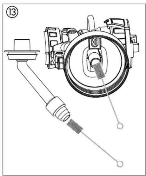
- Clean feed tube and suction nozzle in spray attachment with cleaning brush. (Fig. 13)
-
Take hold of the mixer using the special removal-tool. Lightly compress the removal-tool and take the mixer out 17. of the container (fig. 14).
-
Clean the mixer thoroughly especially in the small gaps and narrow areas.

IMPORTANT: Never clean containers with pointy or sharp objects. Otherwise you will damage the special coating of the container.
- Clean the inside of the container and mixer-take-up thoroughly with a cloth or brush.

WARNING: There are electric contacts inside the container. Never immerse the container in water or any other kind of liquid. Only clean with a damp cloth.
- Clean the outside of the spray gun and container with a cloth soaked in solvent or water.

Wipe the underside of the container thoroughly, as remains of the paint can interfere with the functionality of the device.
Important: The contact points on the underside of the container must be able to move freely

IMPORTANT! The seal ring in the container is only partially solvent-proof. Do not leave solvents in the container for longer periods.
- Remove the adjusting ring (fig. 16,1) carefully from the union nut (2). Unscrew union nut (2), remove air cap (3), nozzle (4) and nozzle seal (5).
Thoroughly clean all parts.

IMPORTANT! Never clean seals, diaphragm and nozzle or air holes of the spray gun with metal objects.
The ventilation hose and diaphragm are only solvent-resistant to a limited extent. Do not immerse in solvent, only wipe.

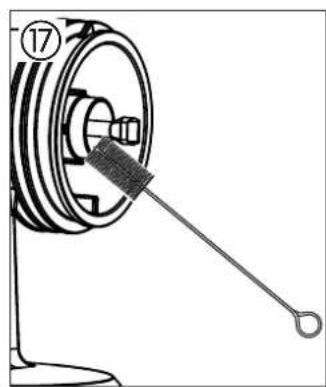
Take special care when cleaning the interstices on the needle (Fig. 17)
- If necessary, remove the cover on the heating station by unscrewing the two screws (fig. 15).
- Wipe off the cover and heating station thoroughly to remove all remains of paint.
If necessary, wipe the control panel with a damp cloth.24.
Assemble the parts again (see "Assembly").25.
13.1 ASSEMBLY
Place the cover back on the heating station and screw into 1. position. When the cover is not in place, the heating and cleaning functions cannot be executed.

IMPORTANT! Follow the steps described below exactly for assembly. Otherwise the spray attachment may be damaged.
-
Push nozzle seal onto the needle so that the groove (slot) points away from the spray attachment. (Fig. 18)
-
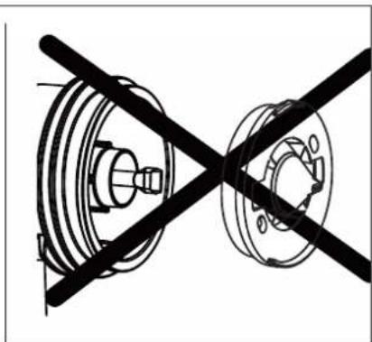
Place nozzle on the needle with recess downwards. Attention: Position of needle must be congruent with the nozzle aperture. (Fig. 19)
-
Place air cap on nozzle (pay attention to recesses in the air cap). (Fig. 20)
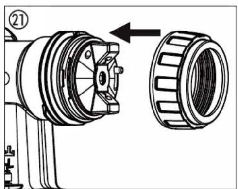
Screw on union nut. (Fig. 21)5.
- Snap the adjusting ring into the union nut. (Fig. 22)
Make sure that the two recesses on the adjusting ring are engaged in the air cap clamps and that the lever for adjusting the spray jet width is located on the pin.
Place the container seal from below on the feed tube and 7. slide it over the collar, while turning the container seal slightly.
- Screw the feed tube with the container seal into the body of the gun.
Warning: Insert feed tube soundly, as otherwise, the mixer can block or be damaged when in use.
- Put the mixer back into the container using the removal-tool and click into place.

In order to mount the gun more easily apply lubricating grease (enclosed) liberally to the O-ring at the spray attachment and to the O-ring of the plug connection of the air hose (Fig. 23).
14 MAINTENANCE
14.1 AIR FILTER

Attention! Never operate the device with the air filter soiled or missing, as dirt could be sucked up and affect the operation of the device.
Always check the air filter before starting work.
- Unplug the power plug.
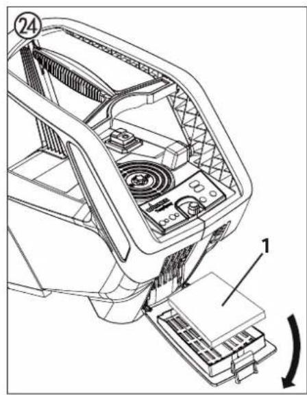
- Open the cover of the air filter compartment (Fig. 24).
- Clean (blow out) or replace the air filter (Fig. 24,1) depending on the degree of soiling.
14.2 AIR RELIEF VALVE

If paint has entered the ventilation hose, proceed as follows:
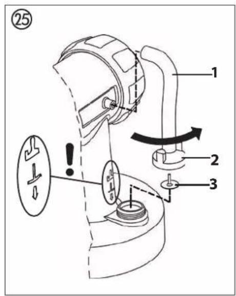
- Pull the ventilating hose (Fig. 25, 1) at the top from the gun body. Screw off the valve cover (2). Remove the diaphragm (3). Clean all the parts carefully.

CAUTION! The ventilation hose and diaphragm are only solvent-resistant to a limited extent. Do not immerse in solvent, only wipe.
- Place the diaphragm in the valve cover with the pin facing
forward (Also see the marking on the gun body).
Turn the body of the gun upside down and screw on the 3. valve cover from underneath.
- Place the ventilating hose on the valve cover and on the nipple at the gun body.
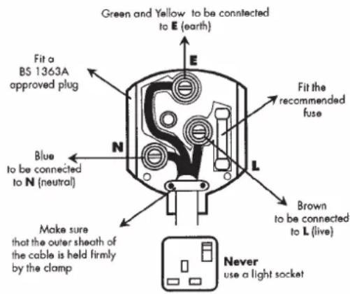
Warning
If the supply cord of this appliance is damaged, it must only be replaced by a repair shop appointed by the manufacturer, because special purpose tools are required.
The wires in this mains lead are coloured in accordance with the following code:
$$ \text { green } / \text { yellow } = \text { earth } $$
$$ \text { blue } = \text { neutral } \quad \text { brown } = \text { live } $$
As the colours of the wires in the mains lead of this appliance may not correspond with the coloured markings identifying the terminals in your plug, proceed as follows:
- The wire which is coloured green and yellow must be connected to the terminal in the plug which is marked with the letter E or by the earth symbol or coloured green or green and yellow.
- The wire which is coloured blue must be connected to the terminal which is marked with the letter N or coloured black.
- The wire which is coloured brown must be connected to the terminal which is marked with the letter L or coloured brown.
- Should the moulded plug have to be replaced, never re-use the defective plug or attempt to plug it into a different 13 A socket. This could result in an electric shock.
- Should it be necessary to exchange the fuse in the plug only use fuses approved by ASTA in accordance with BS 1362. Only 13 Amp fuses may be used.
- To ensure that the fuse and fuse carrier are correctly mounted please observe the provided markings or colour coding in the plug.
- After changing the fuse, always make sure that the fuse carrier is correctly inserted. With out the fuse carrier, it is not permissible to use the plug.
- The correct fuses and fuse carriers are available from your local electrical supplies stockist.
15 correction of MAIfunctionS
| MALFUNCTION CAUSE REMEDY | ||
| The unit will not start No mains vol | voltageDevice overheatedSlider damaged or defect | CheckUnplug the power plug, let the device cool down approx. 30 minutes, do not bend the hose, check the air filter, do not cover the intake slotsPlease contact Wagner Service |
| Heating process/cleaning does not start (both yellow control lamps flash at the same time) | Incorrect spray attachment in useSpray attachment is not positioned correctly on the heating stationHeating station or container contacts are dirtyHeating station cover is not in positionThermal fuse in container has been triggeredContacts in container or heating station are defect | Use TempSpray spray attachmentReposition spray attachment correctlyCleanMount coverLeave container to cool down for about 5 minutesPlease contact Wagner Service |
| No coating material emerges from the nozzle | Nozzle cloggedMaterial volume setting too lowPaint container seal damagedNo pressure build-up in containerContainer emptyVentilation hose loose/damagedFeed tube looseFeed tube / feed tube filter cloggedAir vent on feed tube blockedDiaphragm stuck | CleanIncrease volumeReplaceTighten containerRefillInsert or replaceInsertClean or use another filterCleanRemove and clean (see section 14.2) |
| Coating material drips from the nozzle | Air cap, nozzle or needle soiledSpray attachment incorrectly assembledNozzle looseNozzle seal wornNozzle wornNeedle worn | CleanAssemble correctly (see section 13.1)Tighten Union nutChangeChangeUse new spray attachment |
| Atomisation too coarse Material | volume too largeNozzle contaminatedViscosity of coating material too highToo little pressure build-up in containerAir filter heavily soiledAmount of air too lowAir hose damaged | Reduce volumeCleanDilute furtherTighten containerChange (see section 14.1)Increase volumeCheck and replace if necessary |
| Spray jet pulsates Coating materi | in container running outNozzle seal wornAir filter heavily soiledFeed tube looseFeed tube / feed tube filter clogged | RefillReplaceChange (see section 14.1)InsertClean or use another filter |
| Coating material causes “paint tears | Too much coating material appliedDistance too smallIncorrect spray attachment | Reduce volumeIncrease distanceUse another spray attachment |
| Excessive paint mist (overspray) Distance to the object too largeToo much coating material appliedAmount of air too highCoating substance over-dilutedIncorrect spray attachment | Reduce distanceReduce volumeReduce volumeReduce degree of dilutionUse another spray attachment | |
| Poor spray pattern Paint has been destroyed by overheatingContainer was too hot before the heating process started. The heating process was not executed correctly. | Reduce temperature setting (adhere to data sheet provided by manufacturer)Allow container to cool briefly and then reheat paint | |
| Paint in the ventilating hose Diaphragm soiledDiaphragm defective | Clean the diaphragm (see section 14.2)Replace the diaphragm (see section 14.2) | |
| The spray pattern deteriorates during painting | Nozzle/air cap is dirtyThe paint has cooled down too much | Detach the air cap and clean both parts (especially the hole in the middle of the air cap)Reheat the paint |
16 AcceSSorleS And SPAre PArtS
16.1 AcceSSorleS
POS. ORDER NO. DESIGNATION
1 2321 879 StandardSpray spray attachment (yellow) (with 1000 ml container) Processes all standard paints.
2 2321 877 FineSpray spray attachment (brown) (with 1000 ml container) Ideal for low-viscosity paints and glazes.
3 2321 880 WallSpray spray attachment (white) (with 1400 ml container) Designed for processing dispersions.
4 2324 749 Container with cover (1400 ml)
5 2322 451 Container with cover (1000 ml)
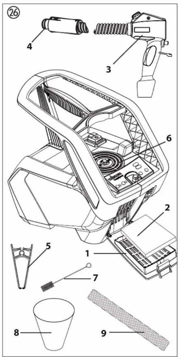
16.2 SPAre PArtS finIShcontrol 6500 (fig. 26)
| POS. | ORDER NO. | DESIGNATION |
| 1 | 2312 650 Cover of air filter compartment | |
| 2 | 2322 446 Air filter (3 pcs.) | |
| 3 | 2314 573 Gun handle with air hose | |
| 4 | 0420 316 O-ring of air hose | |
| 5 | 2307 902 Tool to change mixer | |
| 6 | 2322 477 Heating station cover (incl. screws) | |
| 7 | 0514 209 Cleaning brush | |
| 8 | 2324 745 Funnel (3 pcs.) | |
| 9 | 2324 751 Air hose fixing strap | |
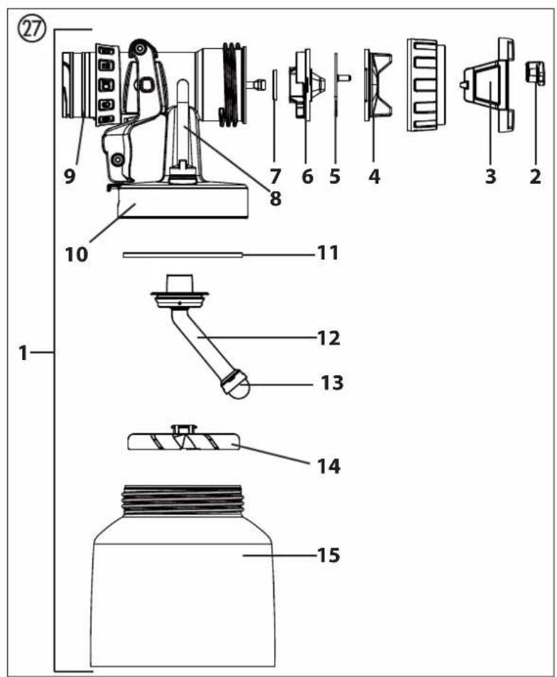
16.3 SPAre PArtS teMPSPrAy SPrAy AttAchMent (red) (flg. 27)
| POS. | ORDER NO. | DESIGNATION |
| 1 2321 878 TempSpray spray attachment (red) (with 600 ml container) | ||
| 2 2316 083 Spray jet width adjusting lever | ||
| 3 | 2314 591 Spray jet adjustment ring | |
| 4 | 2317 807 | Air cap |
| 5 | 2314 585 | Air screen |
| 6 | 2317 423 | Nozzle (S 4.1) |
| 7 | 2323 934 | Nozzle seal |
| 8 | 2304 027 | Ventilating hose, valve cover, diaphragm |
| 9 | 0417 308 | O-ring of spray attachment |
| 10 | 2324 250 | Body of gun (including position 7-9) |
| 11 | 2319 223 | Container seal |
| 12 | 2319 221 | Feed tube |
| 13 | 2324 248 | Fine feed tube filter (red, 5 pc.) |
| 2324 249 | Coarse feed tube filter (white, 5 pc.) | |
| 14 | 2308 678 | Mixer |
| 15 | 2322 475 | Container with cover 600 ml |
| 2315 539 | Lubricating grease | |
TESTING OF THE UNIT
For safety reasons, we would recommend having the device checked by an expert as required but at least every 12 months to ensure that it can continue to operate safely.
In the case of unused devices, the check can be postponed until they are next started up.
All (potentially deviating) national inspection and maintenance regulations must also be observed.
If you have any questions, please contact the customer service team at Wagner.
IMPORTANT INFORMATION ON PRODUCT LIABILITY
An EU directive valid since 01.01.1990 specifies that the manufacturer is only liable for his products if all the parts originate from the manufactured or are approved by him, and if the units are mounted and operated properly.
If accessories or spare parts from third parties are used, liability can be partially or completely inapplicable. In extreme cases the responsible authorities can prohibit the use of the entire unit (German industrial employer's liability insurance association and factory inspectorate).
With original WAGNER accessories and spare parts, compliance with all safety regulations is guaranteed.
NOTE ON DISPOSAL
In observance of the European Directive 2002/96/EC on waste electrical and electronic equipment and implementation in accordance with national law, this product is not to be disposed of together with household waste material but must be recycled in an environmentally friendly way!

Wagner or one of our dealers will take back your used Wagner waste electrical or electronic equipment and will dispose of it for you in an environmentally friendly way. Please ask your local Wagner service centre or dealer for details or contact us direct.
GUARANTEE DECLARATION
(Status 01.02.2009)
1. Scope of guarantee
All Wagner professional colour application devices (hereafter referred to as products) are carefully inspected, tested and are subject to strict checks under Wagner quality assurance. Wagner exclusively issues extended guarantees to commercial or professional users (hereafter referred to as “customer”) who have purchased the product in an authorised specialist shop, and which relate to the products listed for that customer on the Internet under www.wagner-group.com/profi-guarantee.
The buyer's claim for liability for defects from the purchase agreement with the seller as well as statutory rights are not impaired by this guarantee.
We provide a guarantee in that we decide whether to replace or repair the product or individual parts, or take the device back and reimburse the purchase price. The costs for materials and working hours are our responsibility. Replaced products or parts become our property.
2. Guarantee period and registration
The guarantee period amounts to 36 months. For industrial use or equal wear, such as shift operations in particular, or in the event of rentals it amounts to 12 months.
Systems driven by petrol or air are also guaranteed for a 12 month period.
The guarantee period begins with the day of delivery by the authorised specialist shop. The date on the original purchase document is authoritative.
For all products bought in authorised specialist shops from 01.02.2009 the guarantee period is extended to 24 months providing the buyer of these devices registers in accordance with the following conditions within 4 weeks of the day of delivery by the authorised specialist shop.
Registration can be completed on the Internet under www.wagner-group.com/profi-guarantee.
The guarantee certificate is valid as confirmation, as is the original purchase document that carries the date of the purchase. Registration is only possible if the buyer is in agreement with having the data being stored that is entered during registration.
When services are carried out under guarantee the guarantee period for the product is neither extended nor renewed.
Once the guarantee period has expired, claims made against the guarantee or from the guarantee can no longer be enforced.
3. Handling
If defects can be seen in the materials, processing or performance of the device during the guarantee period, guarantee claims must be made immediately, or at the latest within a period of 2 weeks.
The authorised specialist shop that delivered the device is entitled to accept guarantee claims. Guarantee claims may also be made to the service centres named in our operating instructions. The product has to be sent without charge or presented together with the original purchase document that includes details of the purchase date and the name of the product. In order to claim for an extension to the guarantee, the guarantee certificate must be included.
The costs as well as the risk of loss or damage to the product in transit or by the centre that accepts the guarantee claims or who delivers the repaired product, are the responsibility of the customer.
4. Exclusion of guarantee
Guarantee claims cannot be considered
-for parts that are subject to wear and tear due to use or other natural wear and tear, as well as defects in the product that are a result of natural wear and tear, or wear and tear due to use. This includes in particular cables, valves, packaging, jets, cylinders, pistons, means-carrying housing components, filters, pipes, seals, rotors, stators, etc. Damage due to wear and tear that is caused in particular by sanded coating materials, such as dispersions, plaster, putty, adhesives, glazes, quartz foundation.
-in the event of errors in devices that are due to non-compliance with the operating instructions, unsuitable or unprofessional use, incorrect assembly and/or commissioning by the buyer or by a third party, or utilisation other than is intended, abnormal ambient conditions, unsuitable coating materials, unsuitable operating conditions, operation with the incorrect mains voltage supply/frequency, over-operation or defective servicing or care and/or cleaning.
-for errors in the device that have been caused by using accessory parts, additional components or spare parts that are not original Wagner parts.
-for products to which modifications or additions have been carried out.
-for products where the serial number has been removed or is illegible
-for products to which attempts at repairs have been carried out by unauthorised persons.
-for products with slight deviations from the target properties, which are negligible with regard to the value and usability of the device.
-for products that have been partially or fully taken apart.
5. Additional regulations.
The above guarantees apply exclusively to products that have been bought by authorised specialist shops in the EU, CIS, Australia and are used within the reference country.
If the check shows that the case is not a guarantee case, repairs are carried out at the expense of the buyer.
The above regulations manage the legal relationship to us concludingly. Additional claims, in particular for damages and losses of any type, which occur as a result of the product or its use, are excluded from the product liability act except with regard to the area of application.
Claims for liability for defects to the specialist trader remain unaffected.
German law applies to this guarantee. The contractual language is German. In the event that the meaning of the German and a foreign text of this guarantee deviate from one another, the meaning of the German text has priority.
J. Wagner GmbH
Division Professional Finishing
Otto Lilienthal Strasse 18
88677 Markdorf
Federal Republic of Germany
Subject to modifications
22 Station chauffante
INDICATION DE MISE AU REBUT
Division Professional Finishing
Otto Lilienthal Strasse 18
88677 Markdorf
6 INTRODUCTIE IN HET SPUITEN VOLGENS HET XVLP-PROCÉDÉ
11 ARBEIDSONDERBREKING
Division Professional Finishing
Otto Lilienthal Strasse 18
88677 Markdorf
13 Recipiente (TempCup)
14 Agitador
15 Tubo de subida
16 Junta de recipiente
POS. DENOMINACIÓN
17 Válvula
21 Interruptor ON/OFF (I = ON, 0 = OFF)
Division Professional Finishing
Otto Lilienthal Strasse 18
88677 Markdorf
16 ACCESSORI E RICAMBI 87
16.1 Accessori 87
16.2 Ricambi FinishControl 88
14.2 VALVOLA DI SFIATO

Division Professional Finishing
Otto Lilienthal Strasse 18
88677 Markdorf
16.2 Reservedele FinishControl 102
16.3 Reservedele pistol TempSpray 103
Division Professional Finishing
Otto Lilienthal Strasse 18
88677 Markdorf
Forbundsrepublikken Tyskland
6 INTRODUKTION TILL SPRUTNING MED XVLP _ 111
7 SPRUTMATERIAL 111
6 INTRODUKTION TILL SPRUTNING MED XVLP
Division Professional Finishing
Otto Lilienthal Strasse 18
88677 Markdorf
21 Interruptor principal (I = LIGAR, 0 = DESLIGAR)
Division Professional Finishing
Otto Lilienthal Strasse 18
88677 Markdorf
2006/42/EG, 2004/108/EG, 2002/96/EG 2006/42/EC, 2004/108/EC, 2002/96/EC
specifications, in particular:
notamment:
Normes et specifications techniques
Location, Date Signature
Senior Vice President Head of Development
Global Product Strategy
Responsible person for documents
Responsable de la documentation
2006/42/ EC, 2004/108/EC, 2002/96/EC
2006/42/CE, 2004/108/CE, 2002/96/CE
2006/42/ EF, 2004/108/EF, 2002/96/EF
2006/42/CE, 2004/108/CE, 2002/96/CE
2006/42/CE, 2004/108/CE, 2002/96/CE
Tillämpade harmoniserade standarder, i synnerhet:
Location, Date Signature
GB Wagner Spraytech (UK) Limited
The Coach House
2 Main Road
Middleton Cheney OX17 2ND
Great Britain
UK-Helpline 01295 714200
Fax 01295 710100
enquiries@wagnerspraytech.co.ul
Telefax +34/93/66800555
info@wagnerspain.com
I Wagner colora Srl
Via Fermi, 3
20875 Burago di Molgora (MB)
Italia
Tel. +39/039/625021
Telefax +39/039/685 18 00
info@wagnercolora.com
CH Wagner International AG
Industriestrasse 22
9450 Altstätten
Schweiz
Tel. +41/71 / 7 57 22 11
Telefax +41/71 / 7 57 22 22
wagner@wagner-group.ch
F Wagner France S.a.r.l


- Inhaltsverzeichnis
- Translation of the original operating instructions
- Contents
- SAFETY REGULATIONS
- Safety at the workplace
- Electrical Safety
- Safety of Persons
- Careful Handling and Use of Power Tools
- Service
- Safety instructions for colour application devices
- Risks of Fire and Explosion
- Warning: Danger of injury!
- Wear breathing equipment when spraying.
- Warning: risk of short circuit!
- Warning: risk of electric shock!
- eXPIAnAtory dIAgrAM (flg. 1)
- Setting And dISPIAyS on the control PAnel (flg. 2)
- THE WAGNER CLICK&PAINT SYSTEM
- DISASSEMBLY OF THE SPRAY GUN
- TECHNICAL DATA
- INTRODUCTION TO SPRAYING USING THE XVLP PROCEDURE
- Function description
- COATING MATERIAL
- COATING MATERIALS SUITABLE FOR USE
- COATING MATERIALS NOT SUITABLE FOR USE
- COATING MATERIALS THAT CAN ONLY BE PROCESSED WITH RELEVANT SPRAY ATTACHMENT (ACCESSORIES)
- PREPARING THE COATING MATERIAL
- Coating material purity:
- SETTING THE SPRAY GUN
- SETTING THE REQUIRED SPRAY PATTERN
- SETTING THE AMOUNT OF MATERIAL (FIG. 6)
- SETTING THE AMOUNT OF AIR (FIG. 7)
- ALIGN THE FEED TUBE
- SPRAYING TECHNIQUE
- BREAKS IN WORK
- TRANSPORTATION
- TAKING OUT OF OPERATION AND CLEANING
- ASSEMBLY
- MAINTENANCE
- AIR FILTER
- AIR RELIEF VALVE
- Warning
- AcceSSorleS And SPAre PArtS
- AcceSSorleS
- TESTING OF THE UNIT
- IMPORTANT INFORMATION ON PRODUCT LIABILITY
- NOTE ON DISPOSAL
- GUARANTEE DECLARATION
- Scope of guarantee
- Guarantee period and registration
- Handling
- Exclusion of guarantee
- Additional regulations.
- INDICATION DE MISE AU REBUT
- INTRODUCTIE IN HET SPUITEN VOLGENS HET XVLP-PROCÉDÉ
- ARBEIDSONDERBREKING
- DENOMINACIÓN
- VALVOLA DI SFIATO
- INTRODUKTION TILL SPRUTNING MED XVLP
Brand : WAGNER
Model : FinishControl 6500 TS
Category : Paint spray