Micromot MP 400 - Milling machine PROXXON - Free user manual and instructions
Find the device manual for free Micromot MP 400 PROXXON in PDF.
| Product type | Profiling router |
| Brand | PROXXON |
| Model | Micromot MP 400 |
| Power supply | 220-240 V, 50/60 Hz |
| Power | 100 W |
| Rotation speed | 25 000 tr/min |
| Tool shank diameter | Up to 3.2 mm |
| Tool height | 40 mm |
| Dimensions (L × W × H) | 340 × 100 × 100 mm |
| Weight | 0.8 kg |
| Sound level | 104 dB(A) |
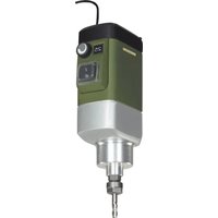
| Main functions | Profiling, grooving, beveling, trimming, cutting of wooden workpieces |
| Height adjustment | Graduated knob with 1 mm per revolution (0.05 mm per graduation) |
| Longitudinal stop | Adjustable on both sides of the router bit |
| Stop square | Mounted in a groove, free movement |
| Transparent guard | Height adjustable, also serves as workpiece hold-down |
| Dust extraction | Integrated rubber suction nozzle |
| Safety equipment | Safety goggles, dust mask, ear protection recommended |
| Maintenance | Clean after each use with vacuum or soft cloth |
| Spare parts | Original PROXXON spare parts available |
| General information | 56-page user manual in French |
Frequently Asked Questions - Micromot MP 400 PROXXON
User questions about Micromot MP 400 PROXXON
0 question about this device. Answer the ones you know or ask your own.
Ask a new question about this device
Download the instructions for your Milling machine in PDF format for free! Find your manual Micromot MP 400 - PROXXON and take your electronic device back in hand. On this page are published all the documents necessary for the use of your device. Micromot MP 400 by PROXXON.
USER MANUAL Micromot MP 400 PROXXON
natural_image
3D rendering of a mechanical device with no visible text or symbolsDeutsch
text_image
Labeled diagram of a mechanical device with numbered components for identificationFig.1a
text_image
Technical diagram of a mechanical device with numbered components and wiring, likely an electrical or industrial component.Fig.1b
natural_image
Technical line drawing of a mechanical device with hands operating it, no visible text or symbolsFig.2
natural_image
Mechanical assembly diagram showing a threaded pipe connection with labeled parts (1, 2), no readable text or symbols present.Fig.2b
text_image
Technical diagram of a mechanical clamp or clamping device with numbered components and directional arrow indicating rotation.Fig.3aFig.3b
text_image
Technical diagram of a mechanical device with labeled parts 2 and 4, showing assembly or assembly steps.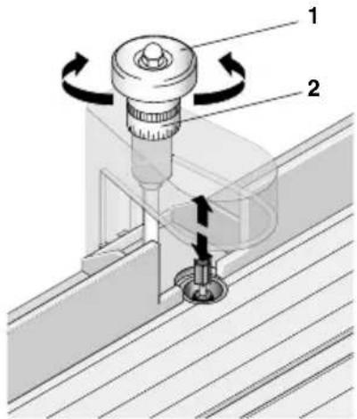
text_image
Technical diagram showing a mechanical assembly with labeled parts and directional arrows indicating motion or force.Fig.4
text_image
Technical diagram of a mechanical device with labeled components and directional arrows indicating motion or force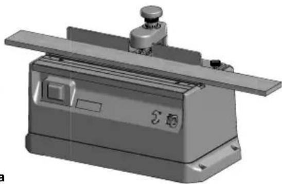
natural_image
3D rendered mechanical component with no visible text or symbolsFig.5a
text_image
Technical diagram of a mechanical device with labeled parts and directional arrows indicating motion or assembly.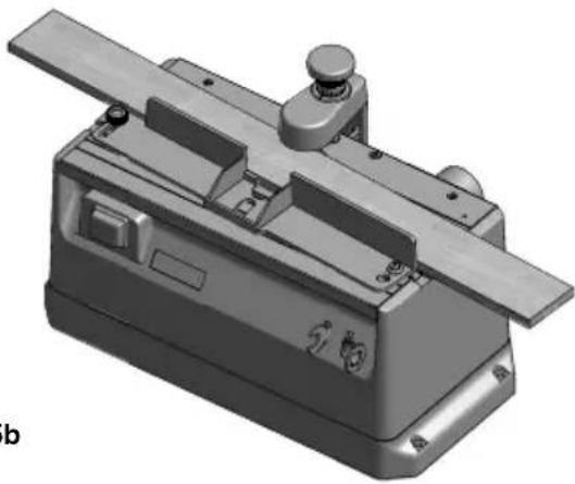
natural_image
3D rendered mechanical component with mounting flanges and a central shaft (no text or symbols visible)Fig.5b
text_image
1 2 3 4 Fig.6PROXXONwillnotbeliebelforthesafefunction ofthedevicefor:
- handlingthatdoesnotcomplywiththeusual intendeduse,
- otherapplicationusesthatarenotstatedinthe instructions,
•disregardofthesafetyregulations,
Youwillnothaveanywarrantyclaimsfor:
•operatingerrors,
- lackofmaintenance.
Foryoursafety, please comply with the safety regulations without fail. Only use original PROXXON spare parts. All rights reserved for further developments in the course of technical progress. Wewish you much success with the device.
Safetyregulations:
Wearpersonalprotectiveequipmentandalwayswearprotectivegoggles.
Dependingonthetypeanduseoftheelectrical device, wearpersonalprotectiveequipment suchasadustmask, non-slipsafetyshoes, a helmetorhearingprotectiontoreducetheriskof injuries. Wearabreathingmaskiftheworkyou dogeneratesdust.
Ifdustextractorsandcollectorscanbeinstalled,thenensurethattheseareconnected andusedcorrectly.
The use of these devices reduce the hazards that dust poses.
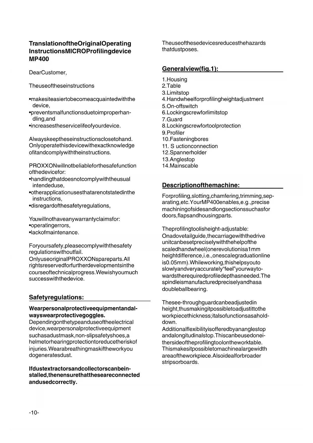
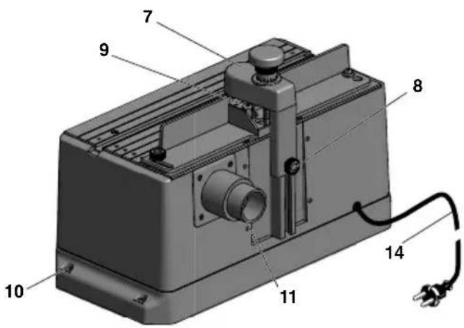
Generalview(fig.1):
1.Housing
2.Table
3.Limitstop
4. Handwheel for profiling height adjustment
5. On-offswitch
6.Lockingscrewforlimitstop
7.Guard
8. Lockingscrewfortoolprotection
9.Profiler
10.Fasteningbores
11. S uctionconnection
12.Spannerholder
13. Anglestop
14.Mainscable
Descriptionofthemachine:
Forprofiling, slotting, chamfering, trimming, separating, etc. Your MP400 enables, e.g., precise machining of sides and long section such as for doors, flaps and housing parts.
Theprofilingtoolisheight-adjustable: Onadovetailguide, thecarriagewiththedrive unitcanbesetpreciselywiththehelpofthe scaledhandwheel(onerevolutionisa1mm heightdifference,i.e.,onescalegraduationline is0.05mm).Whileworking,thishelpsyouto slowlyandveryaccurately“feel”yourwaytowardstherequiredprofiledepthasneeded.The spindleismanufacturedpreciselyandhasa doubleballbearing.
Thesee-throughguardcanbeadjustedin height,thusmakingitpossibletoadjustittothe workpiecethickness;italsofunctionsasaholddown.
Additionalflexibilityisofferedbyananglestop andalongitudinalstop. Thiscanbeusedoneithersideoftheprofilingtoolontheworktable. Thismakesitpossibletomachinealargewidth areaoftheworkpiece. Alsoidealforbroader stripsorboards.
Scopeofdelivery:
1pc.Profilingdevice
2pcs.Spanners
1pc.Suctionconnection
1pc.Anglestop
3pc.Collets
TechnicalData:
Voltage:220-240V,50Hz,\~
Capacity:100watt10min
Workingspeed:25000rpm
Dimensions:340x160x180mm
Weight:approx.2.6kg
Toolshankdiameter:upto3.2mm
Soundpowerlevel:104dB(A)
Workpiece
height/thickness:40mm
Youmustwearhearingprotection whileworking!
Onlyforuseindryrooms
Donotdisposeoftheelectricaldevice inthehouseholdwaste!


Operation:
Beforework:
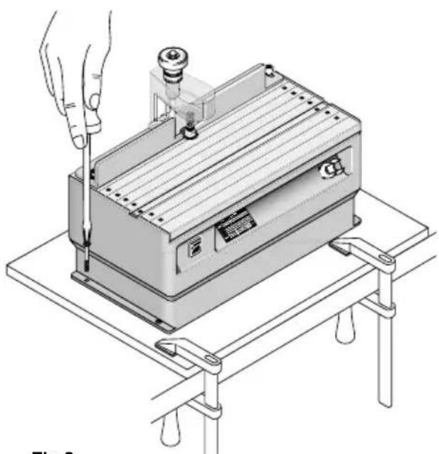
Fasteningtheprofilingdevice(Fig.2):
Beforebeginningwork, fastentheprofilingdevicetoasturdywoodboardwiththematching screws.
Therearedrillholesinthehousingbottomofthe device. Thewoodboardcanthenbefixedtoa tableusingscrewclamps,forexample.
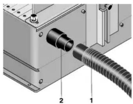
Connectingthevacuumcleaner(Fig.2b):
Caution!
Connectthedustextractor!
It is recommended to always work with dust extraction.
Insertthevacuumhose1ofthevacuumcleaner intotheconnectingpiece2.
Insertingandreplacingtheprofilingtool:
Caution!
For all work described below, it is advisable to position the height-adjustable safety mechanism (see Fig. 1, item 7) all the way up. Disconnect them a ins plug!
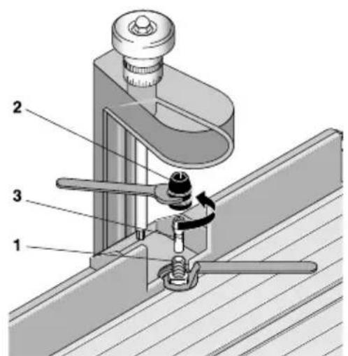
Insertingtheprofilingtool:
Caution!
Makesurethattheprofilerissuitableforspeeds upto25,000revolutionsperminute.
- Holdtheoutputshaft1 (see Fig.3a) with the included open-endspanner and set the otherspannertounscrew and removetheswivelnut2.
- Insert the appropriate collet 3 into the opening of the shaft and screw the swivel nut back on, but donottighten!
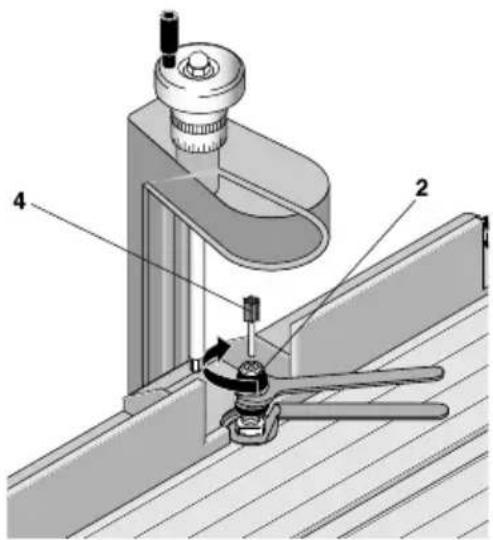
- Insert thematching profiler4(Fig3b).
- TightentheswivelnutasshowninFig.3b.
Replacingthetool:
- Asshownin Fig.3b, loosentheswivelnut, butdonotunscrewit.
- Removetheprofiler4
- Insertanewprofiler.
- Re-tightentheswivelnut
Caution!
Pleasenotethattheshankdiametermustalwayscorrespondtotheinsidediameterofthecollets!Ifthecolletmustbereplacedforthisreason,thenproceedaspreviouslydescribedin"In-sertingtheprofilingtool".
Heightadjustment:
Beforetheprofilingprocess,theheightofthe profilermustbeadjusted.Turnthehandwheel1 (Fig.4)todoso.
Turntotheright:profilermovesup,turntothe left:profilermovesdown.

Tpreciselyachievethedesireddepthforyour profile, thescalering2canbesettozero:
- Simplyturnthehandwheel1 tosettheprofilertoaheightwhereitjustbarelytouches theworkpiece.
- Holdthehandwheelandturnthezeropositionofthescaleringtothemarkingonthe profilingguard.Therequiredprofiledepth cannowbepreciselysetwiththehand wheelincompliancewiththenumericalvaluesonthescalering.
Pleasealsonote:Onefullrevolutionofthehand wheelcorrespondstoatraversepathof1mm, twistingbyonegradationlinecausesaheight adjustmentof0.2mm!
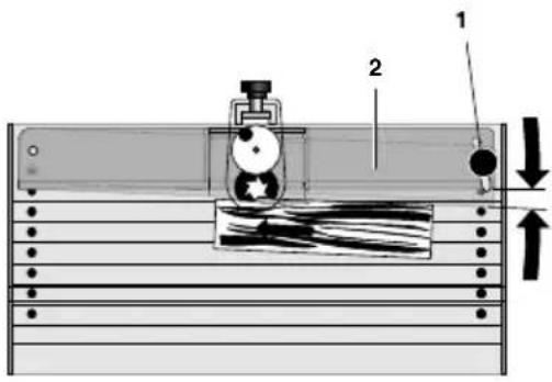
Adjustingthelongitudinalstop(Fig.5and6):
In the positions shown in Fig.5a, the limit stop is suitable for manufacturing chamfers or slots in the front side of strips.
- Loosenknurledscrew1
- Turnlongitudinalstop2tosetthedesired distance
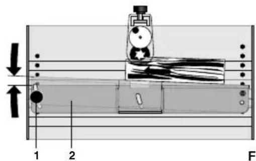
- Retightenknurledscrew If slotsorthelikewillbemadeinwiderstripsor boards, the longitudinalstopcanalsobemountedinthepositionasshowninFig.5b.
Toremountthelongitudinalstop,pleaseproceed asfollows:
Caution!
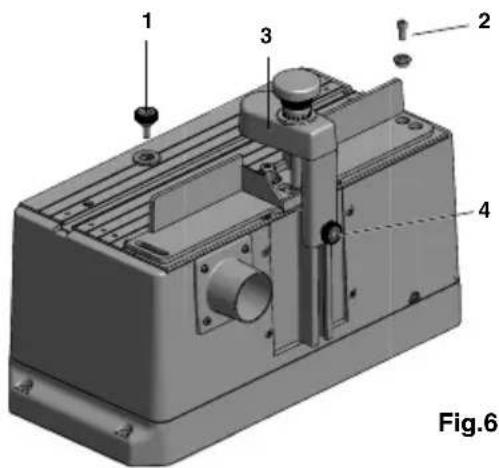
Itmaybenecessarytoremovetheguard(Item 3, Fig.6) forthis. Todoso, releaseknurled screw4 and pullup the guard to remove. When replacing the guard, makes sure you push the square out properly into other of the aluminium profiles that you correctly "hit" the hexagon socket head of the spindle in the work table of the profiling device with the spring-mounted hexagon at them millerguard!
- Completely unscrew the knurledscrew and the Allenscrew 1 and 2 (Fig.6) and remove together with the associated discs and the bushing.
- Roughlyestimatethedistancetotheprofiler; thelongitudinalstopcanbescrewedintothe matchingthreadedholesintheworktablein thepositionasshowninItem3.Donotfor-
getthebushingandthedisc.Donottighten theknurledscrewatfirst!
- Fineadjustmentmaynowbedoneasdescribedearlierunder“Adjustingthelongitudinalstop”.
Anglestop(Fig.1,Item13):
Thisstopcanbeinsertedintothedesignated slot;itcanbemovedbackandforthhere.Toadjust,releasetheknurlednutandturntheplastic element.
WorkingwiththeMicroprofiler:
Caution!
Alwayswearhearingprotectionwhenworking!
Caution!
Neverworkwithouttheprotectivedevice(Item7, Fig1)!
Theguardmustbeadjustedsothatitcoversthemillingcuttercloselyovertheworkpiece.Useextremecarewhenprofilingworkpiecesover5mmheight/thickness.
Neverreachintotherotatingtool!
Theworkpiecemustonlybesolongandwide sothatitstillfitsontheworktableandcanbe easilyguided(max.approx.200mmx500mm). Themaximumchipthicknessshouldneverexceed1mm.
Tomanufacturetheprofile, theworkpieceisallowedtoglidealongthelimitstopasshownin asinFig.5.
Youmustmakesurethattheprofilinginfeed(the removal)andthepushspeedarenottoogreat! Toomuchremovalandatoogreatpushspeed willleadtobadmillingresultsandstrainthemachinemechanicsunnecessarily. Instead,makeseveraloperatingpassesand readjustthelimitstoportheprofilingheightseveraltimes.
Caution!
It is recommended to always work with dust extraction. Arubbersuction connection at therear of the device has been provided for this purpose. You can easily connect a vacuum cleaner here.
Atiponthismatter:
When using the Proxxon CW-matic vacuum cleaner, manual switching on and off is no longer necessary. The CW-matic is fitted with an automatic control device which switches on and off automatically when the power to oil switched on and off.
Careandmaintenance:
Caution!
Havedefectiveindividualcomponentsreplaced byaspecialistonly.
Caution!
Alwaysunplugthemainsplugduringrepairand adjustingwork!
Theprofilingdeviceisprimarilymaintenance free.Foralongservicelife,youshouldclean yourdeviceaftereveryusewithavacuum cleanerorasoftcloth.Pleasealwaysusethe suctiondevice.
Disposal:
Donotdisposeofthedeviceinthehousehold waste! The device contains material that can be recycled. If you have questions concerning this topic, please contact your municipal disposal company or other appropriatemunicipal institutions.
EUconformitydeclaration
Nameandaddressofthemanufacturer:
PROXXONS.A.
6-10, Härebierg
L-6868Wecker
Devidedesignation:MICROProfilingdevice MP400
ArticleNo.:27050
Wedeclarethattheproductsdescribedmeetthe provisionsofthefollowingEUguidelines:
EUEMCDirective2004/108/EC
Appliedstandards:DINEN55014-1/02.2010
DINEN55014-2/06.2009
DINEN61000-3-2/03.2010
DINEN61000-3-3/06.2009
EUMachineryDirective2006/42/EC
Appliedstandards:DINEN61029-1/01.2010
12.03.2012
TheCEdocumentauthorizedagentisidentical withthesignatory.
Traductiondelanoticed'utilisation originaledelaMicrofraiseàprofiler MP400
Cherclient!
Misure:340x160x180mm
Peso:ca.2.6kg
Diametrocorpoutensile:finoa3,2mm
Livellodipotenzasonora:104dB(A)