FX-FH5in1 - Powered garden tool Fuxtec - Free user manual and instructions
Find the device manual for free FX-FH5in1 Fuxtec in PDF.

| Product type | Multifunction felling lever |
| Brand | Fuxtec |
| Model | FX-FH5in1 |
| Main functions | 5 functions: felling, lifting hook / log turner, trunk support, log lifter, post/stake extractor |
| Power supply | Manual (non-motorized) |
| Main material | Steel |
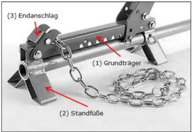
| Included accessories | Base support, legs, stop, claw, pins, handle, chain |
| Safety | Read and understand the manual before use; avoid log falls; use release pins |
| Maintenance and cleaning | Clean after each use; check wear of parts; store in a dry place |
Frequently Asked Questions - FX-FH5in1 Fuxtec
User questions about FX-FH5in1 Fuxtec
0 question about this device. Answer the ones you know or ask your own.
Ask a new question about this device
Download the instructions for your Powered garden tool in PDF format for free! Find your manual FX-FH5in1 - Fuxtec and take your electronic device back in hand. On this page are published all the documents necessary for the use of your device. FX-FH5in1 by Fuxtec.
USER MANUAL FX-FH5in1 Fuxtec
natural_image
Line drawing of a mechanical robotic arm with articulated joints and handle (no text or symbols)
natural_image
Orange icon of a person reading a book on black background (no text or symbols)
DEUTSCHE VERSION....4
VERSION FRANCAISE 10
VERSIONE ITALIANA....16
ENGLISH VERSION 23
VERSION ESPANOLA....30
VERSAO PORTUGUESA....37
NEDERLANDSE VERSIE 44
SVENSK VERSION....51
POLSKA WERSJA JEZYKOWA 57
Sommario
DEUTSCHE VERSION....4
- Assembly of the felling lever 23
- Functions and application of the felling lever 24
VERSION ESPANOLA....30
POLSKA WERSJA JEZYKOWA 57
natural_image
Illustration of a wooden tool with a cylindrical object inserted into a bracket (no text or symbols)Abbildung 4
Manual_FX_FH5in1_Int24_rev44
natural_image
Technical line drawing of a mechanical clamp or tool with a lever and base (no text or symbols)Abbildung 5
natural_image
Technical line drawing of a mechanical clamp or bracket assembly with a tool, labeled 'Abbildung 5' (no other text or symbols)
natural_image
Technical line drawing of a mechanical clamp or lever assembly (no text or symbols)natural_image
Line drawing of a manual lever with a cylindrical component (no text or symbols)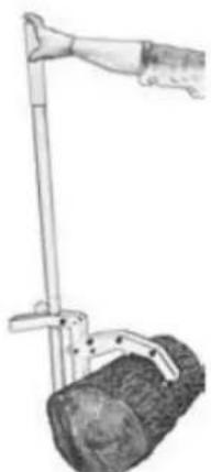
natural_image
Illustration of a hand using a pole-mounted cart with two wheels (no text or symbols)Abbildung 6
natural_image
Diagram of a wooden log being lifted by metal chains, no text or symbols presentWiederholen Sie die
natural_image
Person using a pole marker device in a grassy outdoor setting (no text or symbols visible)Abbildung 8
natural_image
Technical line drawing of a mechanical clamp or lever mechanism (no text or symbols)Abbildung 9
VERSION FRANCAISE
natural_image
Hand-drawn sketch of a mechanical tool with a cylindrical component and lever (no text or symbols)Figure 4
natural_image
Technical line drawing of a mechanical clamp or lever assembly (no text or symbols)- Figure 5
natural_image
Line drawing of a manual lever with a cylindrical component and handle (no text or symbols)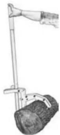
natural_image
Illustration of a hand using a pole-mounted cart with a textured base (no text or symbols)Figure 6
natural_image
Diagram of a wooden log being lifted by metal clamps, no text or symbols presentnatural_image
Person using a power pole in a forest setting, no visible text or symbolsFigure 8
natural_image
Mechanical clamp or lever mechanism diagram with no visible text or symbolsFigure 9
VERSIONE ITALIANA
natural_image
Illustration of a mechanical tool with a textured cylindrical component and lever mechanism (no text or symbols)Figura 4
natural_image
Technical line drawing of a mechanical clamp or lever assembly (no text or symbols)Figura 5
natural_image
Technical line drawing of a mechanical clamp or bracket assembly with a tool, labeled 'Abbildung 5' (no other text or symbols)
natural_image
Technical line drawing of a mechanical clamp or bracket assembly (no text or symbols)natural_image
Diagram of a wooden log being lifted by a metal clamp, no text or symbols presentnatural_image
Person using a power tool in a wooded area, no visible text or symbolsnatural_image
Mechanical lever mechanism diagram showing a handle and lever assembly (no text or labels)Figura 9
ENGLISH VERSION
7. Assembly of the felling lever
- First, mount the base support (1) on the feet (2) with the end stop (3). To do this, use the screws provided (M10*55, washers M10 and the M10 screws that are to be mounted in opposite directions. Please refer to Figure 1 for the corresponding structure.
- Mount the claw (4) with bearing bush, pin (5) and lock nut M10 as shown in Figure 2.
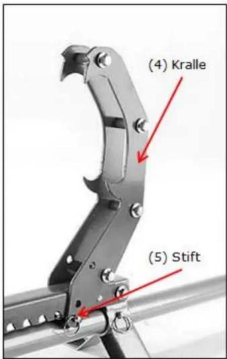
Figure 2
- Install the other components depending on the required function (see Chapter 2)
8. Functions and application of the felling lever
Function 1: Felling lever
natural_image
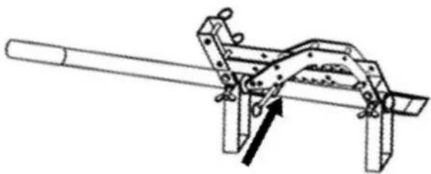
Illustration of a mechanical tool with a cylindrical component and lever mechanism (no text or symbols)- Pass the handle through the feet and fix it with a release pin (9.5x38mm) as shown in Figure 4.
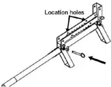
Figure 4
- Then tighten the claw again in one of the pre-determined locking holes on the base support using a release pin (9.5x38mm). The positioning of the claw must be adapted to the respective situation / trunk diameter.
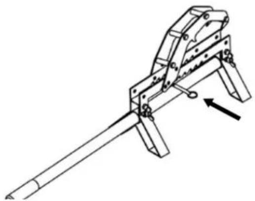
natural_image
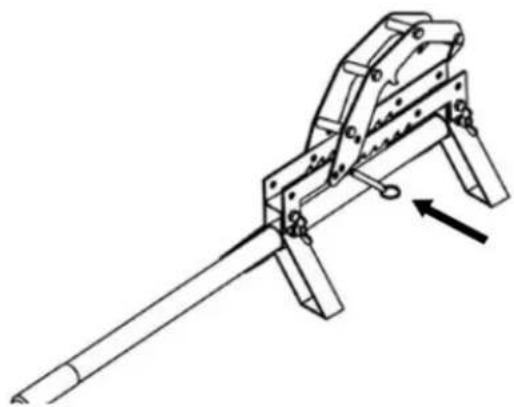
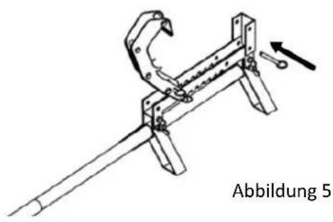
Technical line drawing of a mechanical clamp or lever assembly (no text or symbols)Figure 5
- Finally (if not already done during assembly in Chapter 1), mount the end stop as shown in Figure 5
natural_image
Technical line drawing of a mechanical clamp or bracket assembly with a tool, labeled 'Abbildung 5' (no other text or symbols)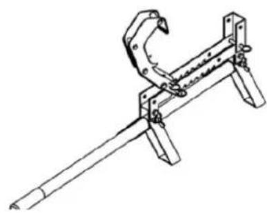
natural_image
Technical line drawing of a mechanical clamp or lever assembly (no text or symbols)Function 2: Edge hook / turning hook / log turner
natural_image
Line drawing of a manual push tool with a cylindrical component and lever (no text or symbols)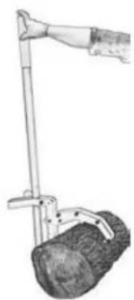
natural_image
Illustration of a hand using a pole-mounted lever to lift a cylindrical object (no text or symbols visible)Abbildung 6
Pass the handle through the feet and fix it with a release pin (9.5x38mm) as shown in Figure 4.
Then tighten the claw into one of the pre-determined locking holes on the base support again using a release pin (9.5x38mm). The positioning of the claw must be adapted to the respective situation / trunk diameter.
Finally (if not already done during assembly in Chapter 1), mount the end stop as shown in Figure 5
Now clamp the trunk between the base support and the claw and turn it to the desired position. Make sure that the trunk does not fall on limbs, otherwise dangerous injuries could occur.
Function 3: Heir
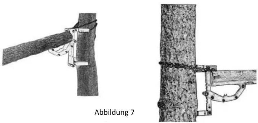
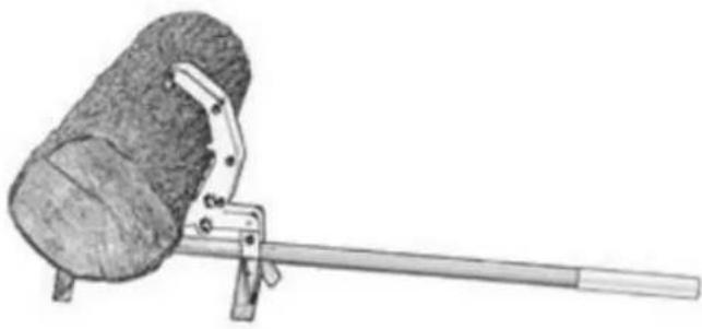
If necessary, remove the handle by pulling the release pin. Tie the base support with the claw mounted to a tree trunk as shown in Figure 7 and secure it with the chain provided. Then clamp the trunk to be worked on into the device. Make sure that the trunk is firmly in place.
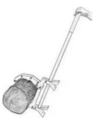
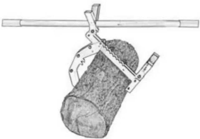
Function 4: Root Carrier
natural_image
Diagram of a wooden log being lifted by a metal clamp, no text or symbols presentRepeat preparation steps 1-3 as described under Function 1 on page 3f.
Mount the handle by passing it through the opening of the first stand leg (do not use the opening of the stand leg at the end stop).
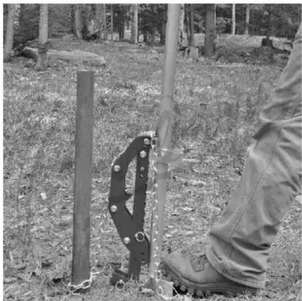
Function 5: Post remover / lifter
Secure the post to be removed to the felling lever using the chain . Then place the fellinglever vertically on the ground as shown in Figure 8 and fix it with one foot on the support leg
natural_image
Person using a manual tool to cut tree bark in a forest, no visible text or symbolsFigure 8
Note : The claw must be mounted on the
base support in the second mounting hole with the release pin.
natural_image
Technical line drawing of a mechanical clamp or lever mechanism (no text or symbols)Figure 9
VERSION ESPANOLA
natural_image
Illustration of a mechanical tool with a cylindrical component and lever mechanism (no text or symbols)Figura 4
natural_image
Technical line drawing of a mechanical clamp or lever assembly (no text or symbols)Figura 5
natural_image
Technical line drawing of a mechanical clamp or bracket assembly with a tool, labeled 'Abbildung 5' (no other text or symbols)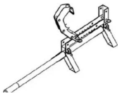
natural_image
Technical line drawing of a mechanical clamp or bracket assembly (no text or symbols)natural_image
Diagram of a wooden log being lifted by a metal clamp, no text or symbols presentnatural_image
Person using a power tool in a wooded area, no visible text or symbolsnatural_image
Mechanical lever mechanism diagram showing a handle and lever assembly (no text or labels)Figura 9
VERSAO PORTUGUESA
natural_image
Illustration of a mechanical tool with a cylindrical component and lever mechanism (no text or symbols)Figura 4
natural_image
Technical line drawing of a mechanical clamp or lever assembly (no text or symbols)Figura 5
natural_image
Technical line drawing of a mechanical clamp or bracket assembly with a tool, labeled 'Abbildung 5' (no other text or symbols)
natural_image
Technical line drawing of a mechanical clamp or bracket assembly (no text or symbols)natural_image
Diagram of a wooden log being lifted by a metal clamp, no text or symbols presentnatural_image
Person using a power tool in a wooded area, no visible text or symbolsnatural_image
Mechanical lever mechanism diagram showing a handle and lever assembly (no text or labels)Figura 9
NEDERLANDSE VERSIE
13. Monteren van de velheffer
natural_image
Illustration of a mechanical tool with a cylindrical component and lever mechanism (no text or symbols)Figuur 4
natural_image
Technical line drawing of a mechanical clamp or lever assembly (no text or symbols)Figuur 5
natural_image
Technical line drawing of a mechanical clamp or bracket assembly with a tool, labeled 'Abbildung 5' (no other text or symbols)
natural_image
Technical line drawing of a mechanical clamp or bracket assembly (no text or symbols)natural_image
Diagram of a wooden log being lifted by a metal clamp, no text or symbols presentnatural_image
Person using a power tool in a wooded area, no visible text or symbolsFiguur 8
natural_image
Mechanical clamp or lever mechanism diagram with no visible text or symbolsFiguur 9
SVENSK VERSION
natural_image
Illustration of a mechanical tool with a textured cylindrical component and lever mechanism (no text or symbols)Figur 4
natural_image
Technical line drawing of a mechanical clamp or lever assembly (no text or symbols)Figur 5
natural_image
Technical line drawing of a mechanical clamp or bracket assembly with a tool, labeled 'Abbildung 5' (no other text or symbols)
natural_image
Technical line drawing of a mechanical clamp or bracket assembly (no text or symbols)natural_image
Diagram of a wooden log being hoisted by a metal clamp, no text or symbols presentnatural_image
Person wearing boots and a metal saw cutting through a wooden post in a grassy outdoor setting (no text or symbols visible)Bild 8
natural_image
Mechanical lever mechanism diagram showing a shaft and lever assembly (no text or labels)Figur 9
POLSKA WERSJA JEZYKOWA
natural_image
Illustration of a mechanical tool with a cylindrical component and lever mechanism (no text or symbols)Rysunek 4
natural_image
Technical line drawing of a mechanical clamp or lever assembly (no text or symbols)Rysunek 5
natural_image
Technical line drawing of a mechanical clamp or bracket assembly with a tool, labeled 'Abbildung 5' (no other text or symbols)
natural_image
Technical line drawing of a mechanical clamp or bracket assembly (no text or symbols)natural_image
Diagram of a wooden log being lifted by a metal clamp, no text or symbols presentnatural_image
Person using a power tool in a wooded area, no visible text or symbolsRysunek 8
natural_image
Mechanical lever mechanism diagram showing a handle and lever assembly (no text or labels)Rysunek 9