FX-PR165 - Powered garden tool Fuxtec - Free user manual and instructions
Find the device manual for free FX-PR165 Fuxtec in PDF.
User questions about FX-PR165 Fuxtec
0 question about this device. Answer the ones you know or ask your own.
Ask a new question about this device
Download the instructions for your Powered garden tool in PDF format for free! Find your manual FX-PR165 - Fuxtec and take your electronic device back in hand. On this page are published all the documents necessary for the use of your device. FX-PR165 by Fuxtec.
USER MANUAL FX-PR165 Fuxtec
natural_image
Illustration of a mechanical engine assembly with hoses and valves (no text or symbols visible)natural_image
Hand holding a black mechanical component with a red arrow indicating rotation (no text or symbols visible)Abb 3
4.2 Kraftstoff
natural_image
Close-up of a mechanical engine component with visible blades and housing (no text or symbols)Abb 6
natural_image
Close-up of a mechanical engine component with cooling fan and housing (no visible text or symbols)Abb 7
natural_image
Close-up of a hand holding a small white plastic bottle next to a mechanical component (no visible text or symbols)Abb 8
8.3 Vergaser
natural_image
Line drawing of hands holding a threaded component with a string attached (no text or symbols)Abb 9
8.5 Schalldämpfer
natural_image
Close-up of hands assembling a mechanical component with a valve and fittings (no visible text or symbols)Abb 10
13. Lieferumfang
Gasoline Pile Driver
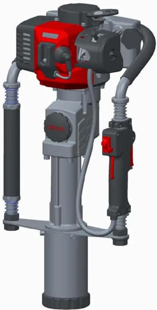
natural_image
3D rendering of a red and gray industrial machine with hydraulic hoses and no visible text or symbols1. Name of Main Parts
| No. | Name of Part | No. | Name of Part | No. | Name of Part |
| 1 | Combination Switch | 2 | Stop Button | 3 | Spark Plug Cap |
| 4 | Ventilation Switch | 5 | Oil Can | 6 | Handle Rack |
| 7 | Fuel Bubble | 8 | Throttle Knob | 9 | Throttle Button |
| 10 | Front Placket | 11 | Piling Socket | 12 | Piling Socket Retainer |
| 13 | Support Plate | 14 | Handle Sleeve | 15 | Grease Cap |
| 16 | Positioning Sleeve | 17 | Starter | 18 | Oil Can Top |
| 19 | Air Filter | 20 | Damping Spring | 21 | Throttle Pull |
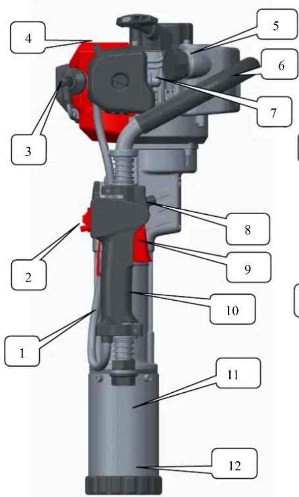
Fig 1
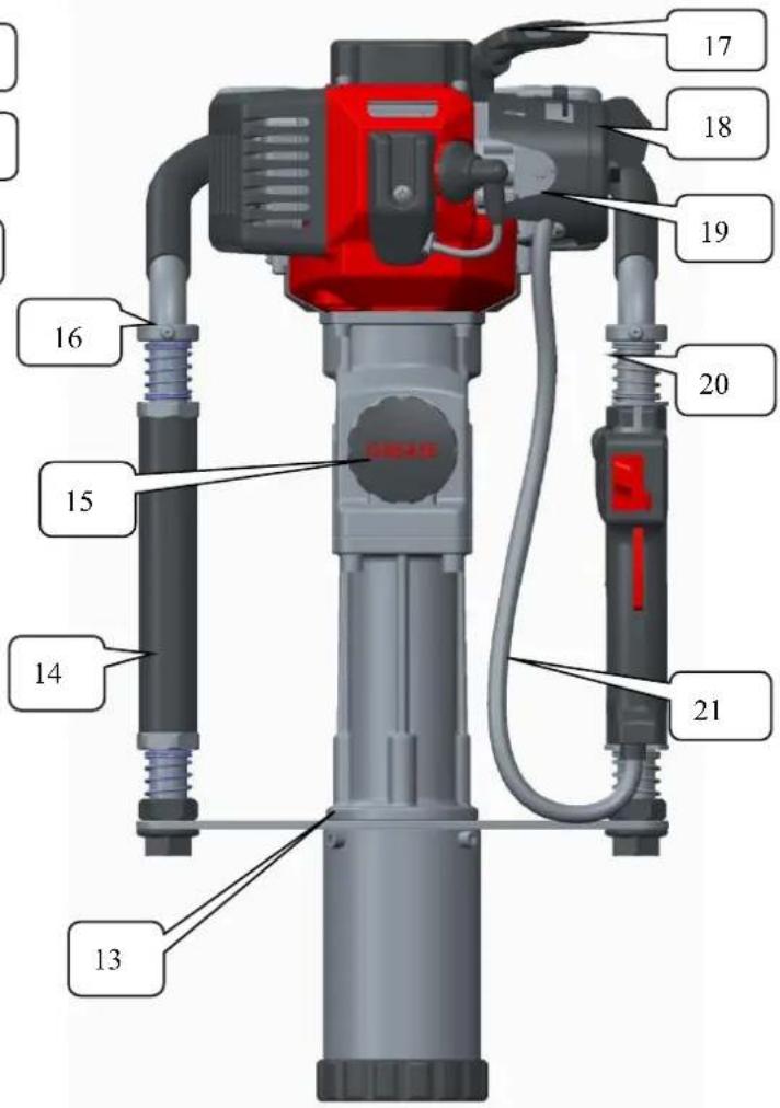
Fig 2
2 Description of Safe Operation
- The operator must wear slip-resistant safety shoes and suitable clothing. For long-time operation, he or she must wear a goggle, a helmet, and earplugs.
- While operating the machine, please keep balance of the body, and stand in front of Air Filter to operate the machine. The operator shall not smoke, eat or chat while operating the machine.
- After starting the machine, do not operate it with one hand.
- When lifting the machine do not pulled the throttle button, which will cause the machine to run at idle.
- Non-staff shall be away from the operation area to avoid injuries.
- Operate the pile driver at the medium speed.
- Keep the handle dry and clean without greasy oil or fuel mixture.
- If operation is stopped midway; be sure to turn off the engine.
- Be sure to check whether fastening screws of the connector is tightened before use. If it's loose, it's necessary to tighten the screws before use.
- Prohibit the use of pure gasoline fuel (no two-stroke oil), shall refer to Chapter 4.2 for recommended ratios of fuel.
- Gasoline is highly flammable. Therefore, replenish fuel in a well-ventilated environment. During fuel filling, gasoline engine must be turned off.
- Do not add too much oil. The oil shall not exceed the neck of oil filer of fuel tank. If fuel spills, start the machine after fuel on the machine volatilizes completely.
- After refueling, tighten the oil lid. During work, check whether oil can is damaged and spills frequently. If damage is found, close down the machine immediately for replacement.
- Reserve oil in storage areas. Remove hidden troubles of fire or open flame.
- While the pile driver is used in closed areas such as tunnels, trenches and deep groove, it's necessary to guarantee normal air circulation to avoid waste gas poisoning and suffocation.
- Forbid quick acceleration or braking so as not to damage the machine.
- Before transport, empty fuel inside the fuel tank to avoid leakage.
- Non-professional maintenance staff are prohibited from dismounting the pile driver to avoid structural damage of parts, shortened service life of the pile driver or accidents.
3. Main Use and Function
3.1 Use: It can be used for outside piling operation of farms, orchard fences or barriers.
3.2 Function
3.2.1 It is the engine-type handheld gasoline pile driver which boasts light weight and low discharge capacity.
3.2.2 The product conforms to the design of man-machine engineering, reduces working strength of the operator to the greatest extent, and boasts simple and comfortable operation. The operator can achieve 360^ all-around operation.
3.2.3 It can regulate impact energy and impact frequency and apply to a variety of piles between 20-80mm (inclusive) in diameter.
3.2.4 Advantage: Save the trouble of using heavy machines such as generator, air compressor and trucking-lorry.
3.2.5 The operating handle of the machine is rubber and plastic sponge handle which can greatly reduce the recoil force of the machine. It's installed with two-way damping spring which makes the user more comfortable.
4.Preparation before Use
4.1 Piling Socket
4.1.1 Install or change piling socket retainer. Select a corresponding retainer according to the sizes of the piling from 20-45 or 46-80, as it's shown in Fig.3., such as
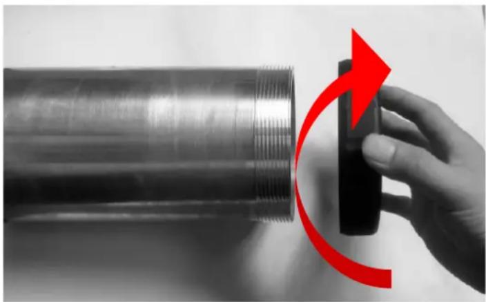
natural_image
Hand holding a black mechanical component with a red curved arrow indicating rotation (no text or symbols visible)Fig 3
4.2 Fuel
Use 90# gasoline and two-stroke special engine oil or above Recommended mixing ratio
| Condition | Gasoline: engine oil |
| Operation within 20 hours | 20:1 |
| Operation of over 20 hours | 25:1 |
4.2.1 Pure gasoline (without two-stroke engine oil) is forbidden as fuel.
4.2.2 Add fuel in a well-ventilated place.
4.2.3 Do not add too much oil. The oil shall not exceed the neck of oil can. If fuel spills, wait until the fuel volatilizes completely and then start the machine.
4.2.4 After refueling, tighten the lid of Oil can.
5.Starting
5.1. Before starting the new machine, press the transparent and semi-circle fuel bubble repeatedly (Fig.4) until carburetor is filled with fuel. (If the engine is cool, close the air door. Open air door after starting.)
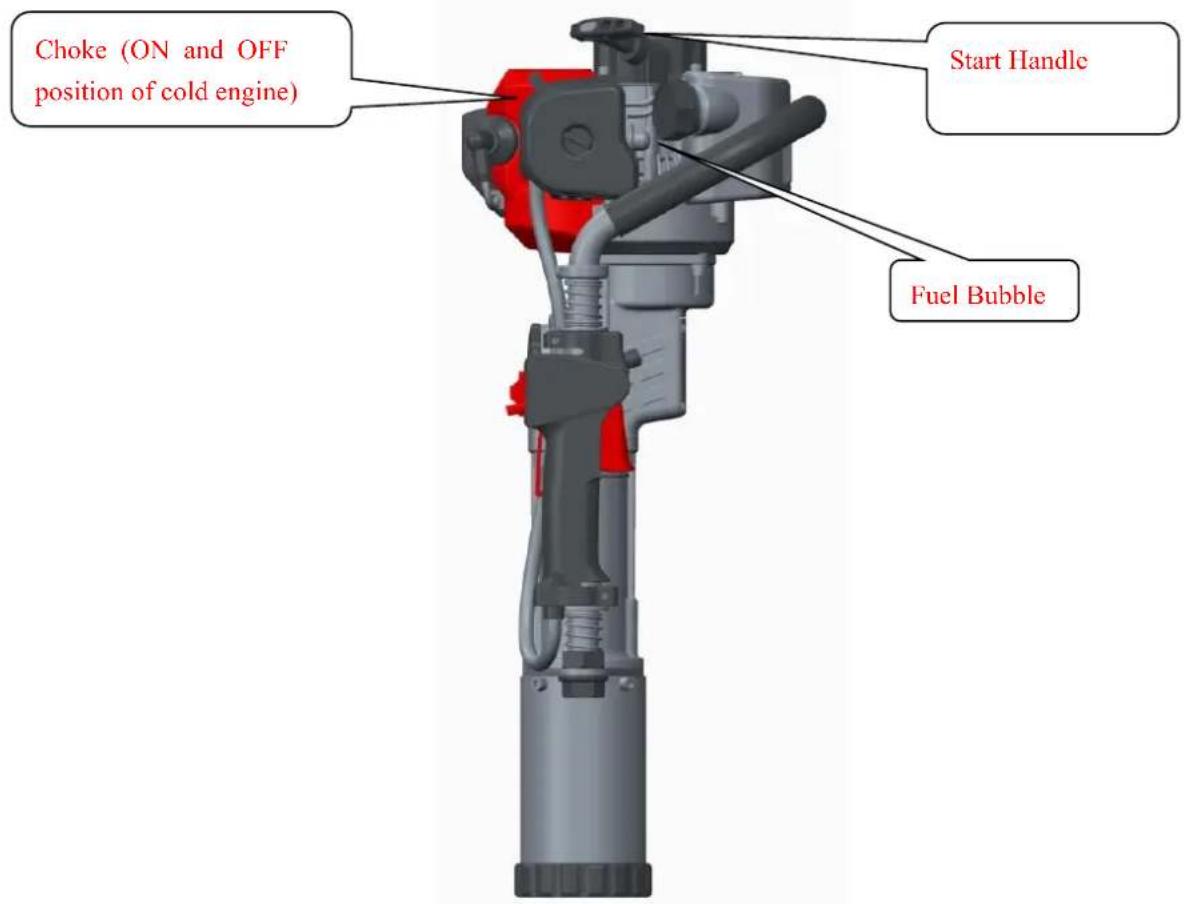
Fig 4
5.2. Set the machine upright according to Fig. 4. Hold the upper part of the handle tightly with one hand while the other pulls the pulling handle of starter for over 50cm quickly. Do not let the pulling handle go back freely in repeated pulling but hold it tightly to avoid injury resulting from quick resilience.
5.3. Start the gasoline engine and then open air door completely. After idle operation for 5 minutes, start normal work.
6. Operation
6.1 After gasoline engine is started, first carry out idle operation for 5 minutes to warm up the machine.
6.2 When the gasoline engine is warmed up, press throttle button to the appropriate regulatory position according to the required impact energy.
Note: The new gasoline pile driver use shall mainly boast low or medium-speed for work in the first 20 hours of the operation and the maximum throttle shall no be used in order to extend the service life.
6.3. Operating speed of gasoline engine shall be low or medium speed.
6.4. High-speed operation of the pile driver during non-piling is prohibited.
7. Turning off the Machine
7.1 Release throttle button and carry out idle running of the machine for 3-5 minutes.
7.2 Pull Stop Button to the position of flameout. See the position of Stop Button in Fig.5
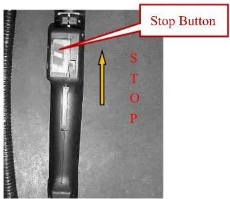
Fig 5
8. Technical Maintenance
8.1 Air Filter
Check air filter regularly. Soot deposit blocking the filter element of the air filter will reduce the power of gasoline engine and service life. If the filter has too much soot deposit, clean it with warm water and detergent, and then install the air filter after wiping it with dry cloth. Filter should be replaced if damaged. Maintenance cycle shall be shortened properly if it's particularly used in the dusty environment..
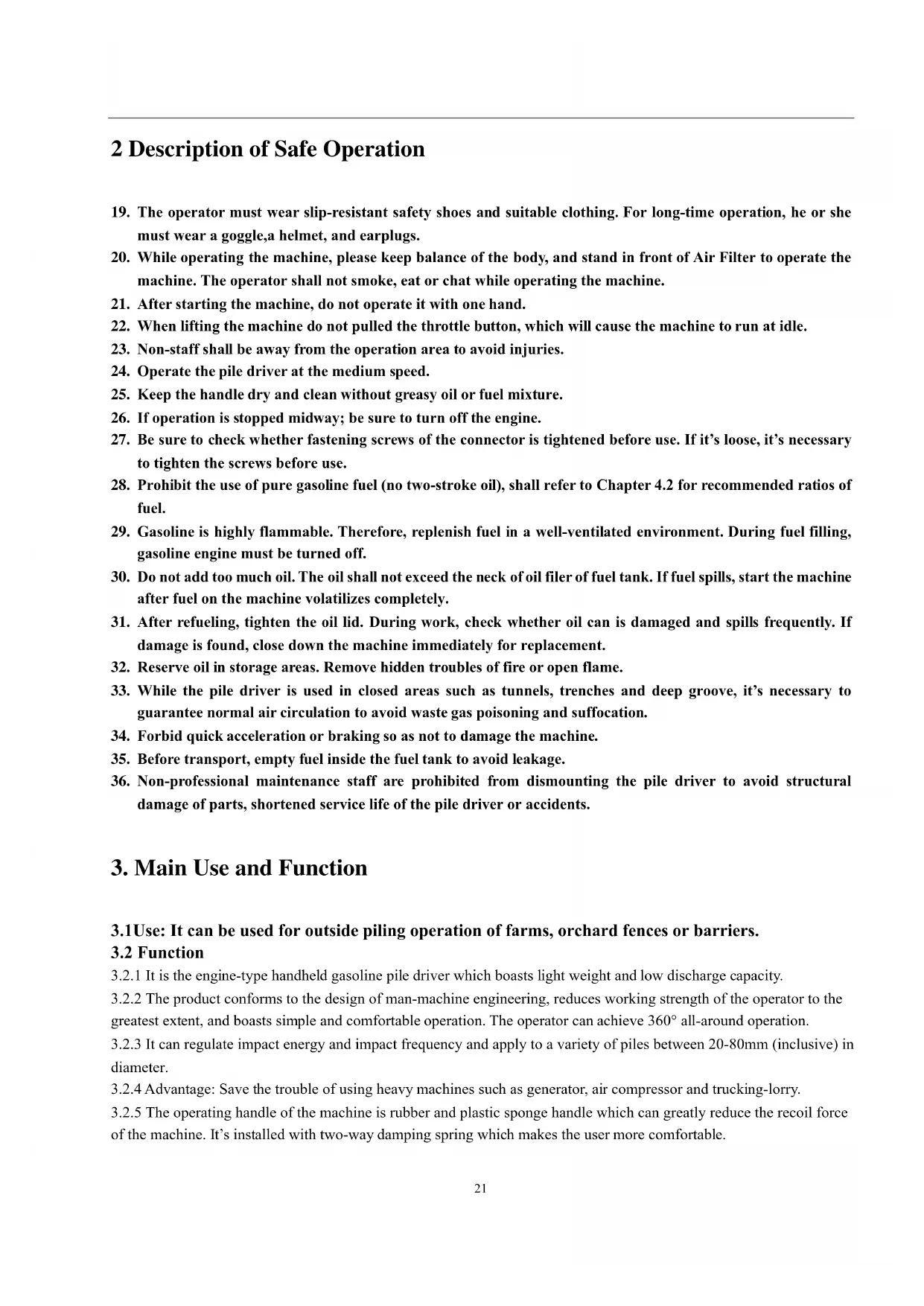
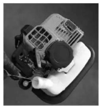
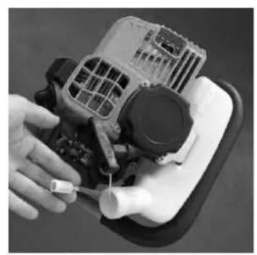
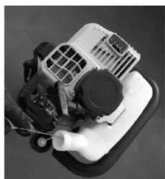
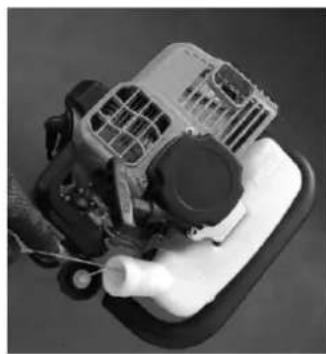
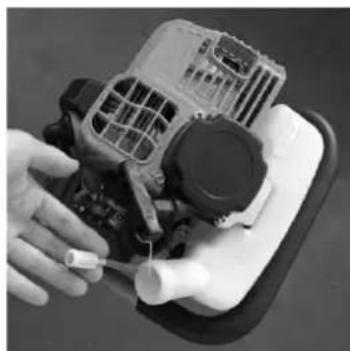
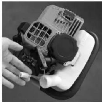
8.2 Fuel filter
If the fuel filter is blocked, the pile driver will have reduced speed and weaker impact energy. Methods: ①Open the oil can lid. Get out the fuel filter from the oil can with metal hook and clean it. ②When cleaning the fuel filter, clean the oil can at the same time as it's shown in Fig.6,7 and8.
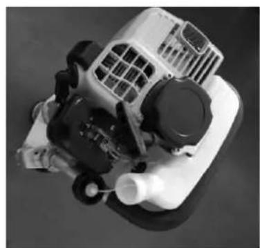
natural_image
Close-up of a mechanical engine component with visible blades and housing (no text or symbols)Fig 6
natural_image
Close-up of a mechanical engine component with visible fan, vent, and handle (no text or symbols)Fig 7
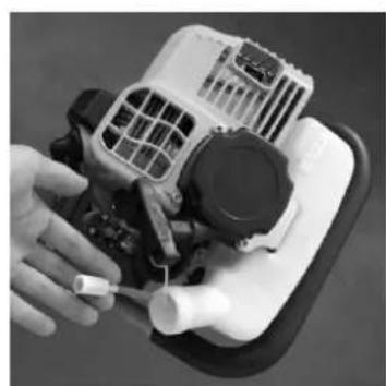
natural_image
Close-up of a hand holding a small white plastic component next to a mechanical device with visible internal components (no text or symbols)Fig 8
8.3 Carburetor
Oil can and carburetor generally have residual oil. After some time, the residual oil will become greasy oil which will block up the oil line, causing incapability of starting the engine. Therefore, when the machine is not used for more than one week, be sure to completely take the fuel out. Method: Pull out the oil inlet pipe, pressthe fuel bubble of the carburetor repeatedly for oil discharge, and press the oil inlet pipe back to its position when fuel in the fuel bubble and oil return pipe is emptied.
8.4 Spark Plug
To ensure normal operation of the engine, the spark plug gap must be proper. Remove sediment with a wire brush. Proper gap of the spark plug is 0.5-0.7 mm. See Fig.9
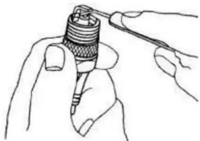
natural_image
Line drawing of hands holding a threaded component with a string attached (no text or symbols)Fig 9
8.5 Silencer
Regularly remove dirt on inlet and outlet of the muffler, or clean dirt in it with detergent.
8.7 The cylinder cooling fin
Regularly remove dust to ensure timely cylinder cooling. The gasoline pile driver is air-cooler type. If dust accumulates on the cylinder heat sink, the cooling effect will be influenced directly which will cause bugs of the gasoline pile driver.
8.7 Refuel lubrication to Impact Cylinder
After the accumulated working hour reaches 50 hours, it is necessary to refuel impact cylinder with 50g specific oil. See Fig.10.
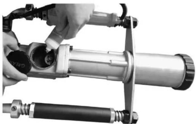
natural_image
Close-up of hands operating a mechanical device with a cylindrical component and two attached hoses (no visible text or symbols)Fig 10
9. Failure Analysis and Its Eliminating Methods
Problem analysis and solving
Example 1: Difficulties in starting engine in cooling state.
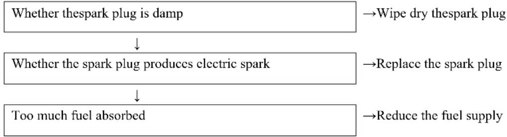
flowchart
graph TD
    A["Whether the spark plug is damp"] --> B["Whether the spark plug produces electric spark"]
    B --> C["Too much fuel absorbed"]
    D["Wipe dry the spark plug"] --> A
    E["Replace the spark plug"] --> B
    F["Reduce the fuel supply"] --> C
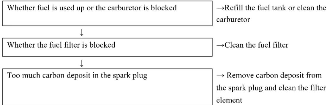
Example 2: Difficulties in restarting after a sudden stop
flowchart
graph TD
    A["Whether fuel is used up or the carburetor is blocked"] --> B["Whether the fuel filter is blocked"]
    B --> C["Too much carbon deposit in the spark plug"]
    A --> D["→Refill the fuel tank or clean the carburetor"]
    B --> E["→Clean the fuel filter"]
    C --> F["→Remove carbon deposit from the spark plug and clean the filter element"]
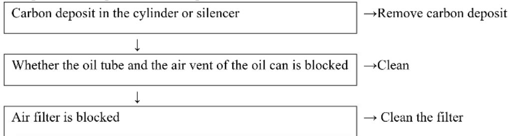
Example 3: Slow speed and weak power
flowchart
graph TD
    A["Carbon deposit in the cylinder or silencer"] --> B{Whether the oil tube and the air vent of the oil can is blocked}
    B --> C["Air filter is blocked"]
    A --> D["Remove carbon deposit"]
    B --> E["Clean"]
    C --> F["Clean the filter"]
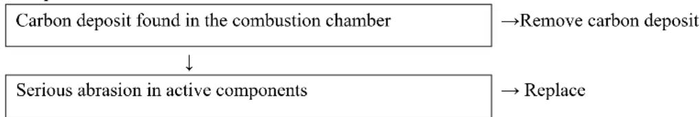
Example 4: Abnormal sound
flowchart
graph TD
    A["Carbon deposit found in the combustion chamber"] --> B["Serious abrasion in active components"]
    B --> C["Remove carbon deposit"]
    B --> D["Replace"]
Example 5: The machine is working normally but the work efficiency is very low

Please contact with local sales agent or contractual maintenance site for maintenance.
10.Key Data of Product
| Gasoline engine type | Single cylinder, air cooling, 2 stroke, cylinder diameter × stroke: 36×32mm |
| Model | FX-PR165 |
| L×W×H(mm) | 635×265×320 |
| Fuel | Mixed oil (Gasoline: two-stroke engine oil=25:1) |
| Oil can capacity | 0.9L |
| Weight (excluding fitting) | 11Kg |
| Displacement | 32.7CC |
| Max power and speed | 0.9KW/9000r/min |
| Max torque and speed | 1.45N.m/5000r/min |
| Gasoline engine no-load speed | 9500 r/min |
| Fuel consumption rate | ≤0.50L/h |
| Impact frequency | 2000BPM |
| Impact energy | 20-55J |
| Carburetor type | MZ10.7 |
| Spark plug type | L6T |
| Starter system | Hand pull start |
| Piles specifications | 20-80mm |
11. Maintenance Cycle
| The following Data are given from the common use of the product. Under worse working conditions such as dusty environment or long work hours of the pile driver, the maintenance cycle should be shortened correspondingly. | Before work | After work or every day | After Filing oil | Every Week | Every Month | Temporary Failure | If necessary | |
| The whole machine | Outlook check (state, tightness of screws) | √ | √ | |||||
| Clean | √ | |||||||
| Control handle/stop button | Function check | √ | √ | |||||
| Air Filter | Clean | √ | √ | |||||
| Replace | √ | |||||||
| Fuel Filter | Check | √ | ||||||
| Replace | √ | |||||||
| Oil can/Oil can cover | Clean | √ | √ | |||||
| Check | √ | √ | ||||||
| Tighten | √ | |||||||
| Reduction Gear Box/Impact Cylinder | Clean | √ | ||||||
| Add oil | √ | |||||||
| Silencer | Check | √ | ||||||
| Remove carbon deposit | √ | |||||||
| Cylinder Cooling Fin | Check | √ | ||||||
| Clean | √ | |||||||
| Spark Plug | Check/Adjust the distance between electrodes | √ | ||||||
| Replace | √ | |||||||
| Screw and Nut | Check | √ | √ | |||||
| Tighten | √ | |||||||
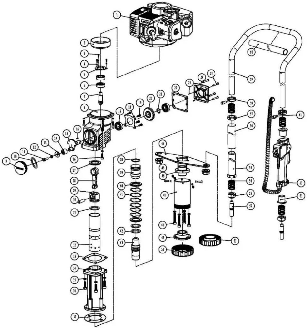
12. Parts List and Exploded View of FX-PR165 Pile Driver
| Parts No. | Name | Qty | Parts No. | Name | Qty | |
| 1 | Gasoline Engine | 1 | 34 | Front Placket | 1 | |
| 2 | Driven Disk | 1 | 35 | Elastic Washer 8 | 8 | |
| 3 | Inner Hexagon Cylindrical-head ScrewM5×12 | 3 | 36 | Inner Hexagon Cylindrical-head Screw M8×20 | 4 | |
| 4 | Elastic Washer 5 | 3 | 37 | Front Paper Pad | 1 | |
| 5 | Bearing Pressing Plate | 1 | 38 | Hammer O-circle | 1 | |
| 6 | Deep Groove Ball Bearings6202-2RS | 3 | 39 | Hammer | 1 | |
| 7 | Smal Bevel Gear7-2 | 1 | 40 | Crush Pad | 2 | |
| 8 | Reduction Gearbox | 1 | 41 | Waved Gasketφ39×46×0.5 | 4 | |
| 9 | Oil Cover | 1 | 42 | Shock O-circle | 2 | |
| 10 | O-ring Oil Coverφ1.5x50 | 1 | 43 | Shock | 1 | |
| 11 | Inner Hexagon Cylindrical-head Screw M6×16 | 1 | 44 | Support Plate | 1 | |
| 12 | Elastic Washer 6 | 9 | 45 | Hexagon Flange Nut M18×1.5 | 2 | |
| 13 | Retainer | 1 | 46 | Impact Socket | 1 | |
| 14 | Needle Roller Bearings HK152316 | 1 | 47 | Piling Socket | 1 | |
| 15 | Impact Crankshaft | 1 | 48 | Inner Hexagon Cylindrical-head Screw M8×40 | 4 | |
| 16 | -A Type Common Flat Key 5×5×10 | 1 | 49 | Inner Pile Head 77 | 1 | |
| 17 | Deep Groove Ball Bearings 6003-2RS | 1 | 50 | Piling Socket Retainer 80 | 1 | |
| 18 | 6003 Bearing Pressing Plate | 1 | 51 | Piling Socket Retainer 45 | 1 | |
| 19 | Cross Pan Head Screw M5×14 | 4 | 52 | Connecting Thread Head | 2 | |
| 20 | Large Bevel Gear-28-2 | 1 | 53 | Step Nut | 2 | |
| 21 | Shaft Retainer 16 | 1 | 54 | Handle Spring38X27X φ 2.5 | 6 | |
| 22 | Rear Paper Pad | 1 | 55 | Handle Sleeve | 1 | |
| 23 | Round Pin 4×10 | 2 | 56 | Handle Soft Sleeve | 1 | |
| 24 | Reduction Gearbox Cover | 1 | 57 | Handle Nut | 1 | |
| 25 | Inner Hexagon Cylindrical-head Screw M5×20 | 4 | 58 | Positioning Sleeve | 2 | |
| 26 | Inner Hexagon Cylindrical-head Screw M6×20 | 8 | 59 | Handle Frame (two-stroke) | 1 | |
| 27 | Cylinder Gaskets | 1 | 60 | Handle Frame Soft Sleeve | 1 | |
| 28 | Impact Connecting Rod | 1 | 61 | Inner Hexagon Cylindrical -head Screw M6×40 | 2 | |
| 29 | Impact Piston | 1 | 62 | Combination Switch | 1 | |
| 30 | Impact Piston Pin | 1 | 63 | Switch Handle Guide Sleeve | 2 | |
| 31 | O-ring Impact Piston | 1 | ||||
| 32 | Impact Cylinder | 1 | ||||
| 33 | Middle Paper Pad | 1 |
13. Packing List of FX-PR165 Pile Driver
Pile driver
Piling Socket Retainer 20\~45mm and 46\~80mm
Oil pot for gasoline mixture
Special oil/grease for cylinder (60g)
Rubber ring (wearing part)
Instructions
The tool package
1 piece of spark plug,
1 piece of spark plug handle,
1 piece of 4mm inner hexagon spanner
1 piece of 5mm inner hexagon spanner
1 piece of 6mm inner hexagon spanner
1 piece of T-shaped inner hexagon spanner
1 piece of straight screw-driver
1 piece of 8-10mm open spanner
Mode d'emploi
Fig 1
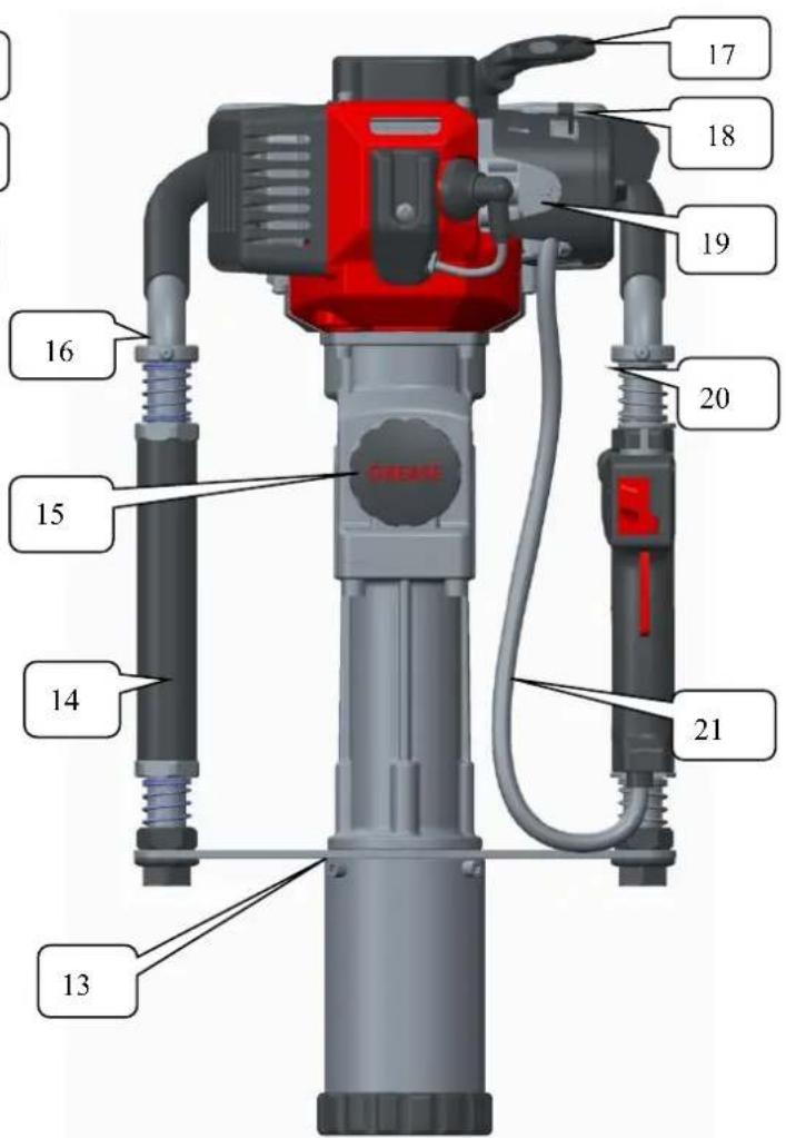
Fig 2
natural_image
Hand holding a black mechanical component with a red arrow indicating rotation (no text or symbols visible)Fig 3
4.2 Carburant
8. Maintenance technique
8.1 Filtre à air
natural_image
Close-up of a mechanical engine component with visible internal structure and housing (no text or symbols)Fig. 6
natural_image
Close-up of a mechanical engine component with visible cooling fan and housing (no text or symbols)Fig. 7
natural_image
Close-up of hands holding a small white plastic component next to an engine block (no visible text or symbols)Fig. 8
8.3 Carburateur
natural_image
Line drawing of hands holding a threaded component (no text or symbols)Fig. 9
natural_image
Close-up of hands assembling a mechanical component with hydraulic hoses (no visible text or symbols)Fig. 10
ill 1

ill 2
natural_image
Hand holding a black mechanical component with a red curved arrow indicating rotation (no text or symbols visible)ill 3
4.2 Carburtante
natural_image
Close-up of a mechanical engine component with visible gears and housing (no text or symbols)ill 6

natural_image
Close-up of a mechanical engine component with visible blades and housing (no text or symbols)ill 7
natural_image
Close-up of a hand holding a small white plastic component with a black lid, next to a white base (no visible text or symbols)ill 8
8.3 Carburatore
natural_image
Line drawing of hands holding a tool with a threaded component (no text or symbols)ill 9
8.5 Silenziatore
natural_image
Close-up of hands using a mechanical tool to adjust a cylindrical component (no visible text or symbols)ill 10