USER MANUAL FX-4MS142LF Fuxtec
natural_image
Line drawing of a mechanical device with two connected components, no text or symbols present

natural_image
Orange icon of a person reading a book on black background (no text or symbols)

natural_image
Icon of a hand pointing at an open book with horizontal lines representing text pages (no actual text or symbols)
Inhalt
DEUTSCHE VERSION....9
ENGLISH VERSION....37
VERSION FRANCAISE....63
- Technical data....38
- Symbols on the machine 39
- General Safety Instructions 41
- Instructions for accessories 43
- Component overview 46
-
Mounting the motor scythe 48
-
Cold start of the machine 52
- Warm start of the machine .... 53
- Trimming techniques....54
- Maintenance and care....55
- Troubleshooting 60
- Customer Service....61
- Warranty....61
- Disposal note 61
- EU Declaration of Conformity....62
VERSION FRANCAISE....63
natural_image
Model of a manual tool with a black-and-white brush and orange handle, extending diagonally (no text or symbols visible)
CE
HALTEN SIE IMMER 15 METER VON ANDEREN PERSON
ABSTAND


natural_image
Close-up of hands using a tool to lift a cylindrical object, with a white arrow indicating the motion direction (no text or symbols visible)
natural_image
Close-up of a metallic mechanical clamp or bracket with a small hole, no visible text or symbols

natural_image
Hand holding a metallic cylindrical tool with a metal clamp (no visible text or symbols)

natural_image
Hand holding a metallic tool with a handle, against a plain white background (no text or symbols visible)
Installation des Schutzschildes
natural_image
Close-up of a black and orange robotic brush tool with a lever handle (no text or symbols visible)
Warnung!
natural_image
Close-up of a black robotic brush with orange outline and mechanical lever (no text or symbols visible)
Schritte:

natural_image
Two-step diagram showing a tool being inserted into a mechanical component, with no visible text or symbols.
Ölstand überprüfen.
natural_image
Close-up of a black and orange portable air purifier with a green arrow indicating direction (no text or symbols visible)

bar
| 类别 | 数值 |
|---|---|
| 5种-30 | -20 |
| 10种-30 | -10 |
| 30 | 30 |
-30℃, 40℃
Umgebungstemperatur

WARNUNG

natural_image
Close-up of a black mechanical device with an orange internal component and a red arrow indicating a downward motion (no text or symbols)

natural_image
Close-up of a mechanical device with orange and black components, showing a green arrow pointing to a component (no text or symbols visible)

natural_image
Close-up of a mechanical device with orange and black casing, showing internal components and a green arrow pointing to a detail (no text or symbols visible)
natural_image
Technical line drawing of a mechanical device with a downward arrow indicator (no text or symbols present)
natural_image
Technical line drawing of a mechanical assembly with a tool and base component (no text or symbols)
9. Trimmtechniken
natural_image
Diagram of a mechanical fan or impeller with motion arrows indicating airflow or movement (no text or symbols)
TRIMMEN UM BÄUME
natural_image
Close-up of hands holding a small black object with a white tool, possibly a tool or device (no visible text or symbols)
natural_image
Close-up of hands holding a black mechanical component (no visible text or symbols)
natural_image
Close-up of hands holding a black mechanical component with wires, against a cloudy sky background (no text or symbols visible)
natural_image
Close-up of hands holding a black cylindrical object (no visible text or symbols)
natural_image
Technical line drawing of a mechanical component with no visible text or symbols
WARNUNG

natural_image
Close-up of a mechanical component with labeled parts F and E, showing yellow material and a ruler (no text or symbols beyond labels)
EC Declaration of Conformity
| Hiermit erklären wir, | FUXTEC GMBH |
| We herewith declare, | KAPPSTRAße 69, 71083 HERRENBERG, GERMANY |
that the following machine complies with the appropriate basic safety and health requirements of the EC Directive based on its design and type, as brought into circulation by us.
In case of alteration of the machine, not agreed upon by us, this declaration will lose its validity
Applicable Harmonized Standards:
Authorized Signature/Date/ Place:
C. Jille
L. Zirkler, 07.06.2023
name and address of the person authorised to
compile the technical file,
ENGLISH VERSION
ORIGINAL USER MANUAL
Petrol brush cutter/grass trimmer
FX-4MS142

natural_image
Exterior view of a manual tool with a black-and-white striped extending rod and orange-handled handle (no text or symbols visible)
CE
Your new device has been developed and designed to meet FUXTEC's high standards, such as easy operation and user safety. Properly treated, this device will serve you well for years to come.

WARNING: To reduce the risk of injury, the user must read and understand this manual before operating the device.
FUXTEC GMBH
KAPPSTRAße 69, 71083 HERRENBERG, GERMANY
We are constantly striving to improve our products. Therefore technical data and illustrations can change!
- Technical data
| Type | FX-4MS142 |
| Engine type | 142F, air-cooled; 4-stroke |
| Cubic capacity | 42.5cm^3 |
| Maximum output power (kW)(in accordance with ISO 8893) | 1.25 kW / 6.500min^-1 |
| The maximum speed of the engine | 10.500 min^-1 |
| Idle speed of the machine | 3.000 ±200min^-1 |
| LPA at the operator station | 104dB(A) (K=3dB) |
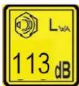
| Guaranteed LWA | 113dB(A) |
| Maximum vibration values on the left handle | 8.210m/s^2 k=1.5m/s^2 |
| Maximum vibration values on the right handle | 8.265m/s^2 k=1.5m/s^2 |
| Maximum diameter of the thread | Φ440mm (Φ2.5mm) |
| Rotation direction of the cutting device | Counterclockwise (see the mark on the plate) |
| Number of the handle | 2 pieces |
| Dry weight (kg) | 8.05 |
| Fuel tank capacity (ml) | 550 |
| Oil tank capacity (ml) | 100ml |
| Oil | FUXTEC 4-stroke oil (SAE30) |
| Fuel consumption (kg/h) (in accordance with ISO 8893) | 0.89 |
| Specific fuel consumption (g/kWh) (in accordance with ISO 8893) | 380 |
| Weight (net/gross) in (kg) | 8.05 / 10,0 |
17. Symbols on the machine
 | WARNING! IMPROPER HANDLING CANLEAD TO SERIOUS INJURY |
 | READ AND UNDERSTAND THIS USER MANUAL BEFORE USE. |
 | ALWAYS WEAR EYE PROTECTION, EAR PROTECTION, AND HEAD PROTECTION |
 | WEAR FOOT PROTECTION. |
 | WEAR GLOVES (Sharp edge!). |
 | DO NOT TOUCH THE ROTATING BLADE,DANGER OF INJURY |
 | ALWAYS KEEP 15 METERS AWAY FROM OTHER PEOPLE |
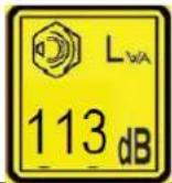 | THE GUARANTEED NOISE LEVEL CORRESPONDS TO THE LEGALNOISE GUIDELINES |
 | WARNING OF FLYING OBJECTS |
 | NO SMOKING AND OPEN FLAMES ON THE DEVICE |
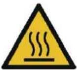 | WARNING:DANGER OF HOT COMPONENTS |
 | ALWAYS TURN THE MACHINE ON AND MAKE SURE THE CUTTING TOOL IS STOPPED BEFORE CLEANING, REMOVING, OR ADJUSTING THE BLADE. |
 | WARNING:FUMES FROM THIS PRODUCT CONTAINCHEMICALS THAT CAUSE CANCER, BIRTH DEFECTSAND FURTHER CAN LEAD |
 | WARNING! NEVER CHANGE THE MACHINE. IMPROPER USE OF THE MACHINE CAN CAUSE SERIOUS OR FATAL PERSONAL INJURY. |
 | Before use, fill in 70ml of engine oil 4 strokes and check every 10 hours. |
 | Warning! Flammable materials! |
 | The maximum speed of the spindle (lawn trimmer): 6600 min ^-1 |
 | The maximum speed of the spindle (motor scythe):7100 min ^-1 |
| Please follow the instructions for refueling |
FUXTEC
Do not allow others to use this machine unless they are fully responsible and have read and understood the machine manual and are trained in its operation.

Extensive use of a tool exposes the user to shocks that can lead to white finger disease (Raynaud's syndrome) or carpal tunnel syndrome. This condition reduces the hand's ability to feel and regulate temperatures, causes numbness and sensations of heat, and can lead to nerve and circulatory damage and tissue death. Not all factors leading to white finger disease are known. Still, cold weather, smoking, and conditions affecting blood vessels and circulation, as well as extensive or prolonged exposure to shocks, are mentioned as factors in the development of white finger disease. To reduce the risk of white finger disease and carpal tunnel syndrome, please note the following
Wear gloves and keep your hands warm.
Take regular breaks.
All the above precautions cannot eliminate the risk of white finger disease or carpal tunnel syndrome. Long-term and regular users are, therefore, advised to monitor the condition of their hands and fingers closely. Consult a doctor immediately if any of the above symptoms occur.

The operating noise of the tool may damage your hearing. Wear a sound-proofing (Oropax or ear muffs) to protect it. Long-term and regular users are recommended to
check your hearing regularly. Be especially vigilant and careful when wearing hearing protection as it limits your ability to hear warnings (cries, alarms, etc.).
● WARNING: Some noise exposure from this device cannot be avoided. Do not work in noisy environments during approved and designated times. If necessary, observe rest periods and limit the working time to the absolute minimum. For your protection and protection of persons in the vicinity, wear suitable hearing protection.
18. General Safety Instructions
This machine may only be used for mowing or trimming grass, weeds, and undergrowth. Never use it for other purposes, as this may cause injuries!
Correct safety instructions must be observed. DO NOT EXPOSE YOURSELF OR OTHERS TO DANGER. Follow these general safety instructions.
● Always wear safety glasses for eye protection. Long hair must be tied back. Do not wear loose clothing or jewelry that can get caught in moving parts of the machine. Safe, strong, non-slip safety shoes must always be worn. It is recommended that legs and feet are covered to protect against fly debris during operation.
- Check the entire machine for loose parts over (nut, bolt, screw, etc.). Maintain or replace them if necessary,
before you use the device. Do not use accessories with this drive head other than those recommended by our company. Otherwise, severe injuries to the user or bystanders and damage to the machine may result.
- Keep the handles free of oil and fuel.
● Always use the correct handles and shoulder strap when cutting.
- Do not smoke when mixing the fuel or filling the tank.
- Do not mix fuel in a closed room or near open fires. Ensure sufficient ventilation/air circulation.
- Mix and store the fuel mixture in a marked container approved for such consumption according to local regulations.
● Never remove the fuel tank cap while the machine is running.
- Do not operate the machine in a closed room or building. Exhaust gases contain dangerous carbon monoxide.
- Do not attempt to adjust the machine while running or carrying the device. Always adjust the machine on a flat, free surface.
- Do not use the machine if it is damaged. Never remove the protection of the device. Otherwise, severe injuries of the operator or spectators, as well as damage to the device, can result.
- Check the area to be cut and remove any debris that may be entangled in the nylon cutting head or cutting blade. Also, remove any objects that the machine may throw around while cutting.
● Never leave the machine unattended.
- Do not reach far forward. Maintain a firm stand and balance at all times. Do not let the machine run while standing on a rope ladder or any other unstable standing position.
● Children must not have access to the machine. Spectators should be kept at a safe distance from the work area, at least 15
METERS.
- Keep hands and feet free of the nylon cutting head or metal blade during the operation.
- Do not use the machine if you are tired, sick, or under the influence of medication, drugs, or alcohol.
-
Use an undamaged nylon cutting head. If you hit a stone or any other obstacle, stop the machine and check the nylon cutting head. Never use a defective or unbalanced nylon cutting head.
-
Before starting, after failure or impact, be sure to check the device and make sure it is in good condition.
● Attention! Local regulations may limit the use of the machine.
● Always keep the device with the cutting tool in good condition.
- Note, improper maintenance, use of non-compliant spare parts, or removal or modification of safety devices can cause damage to the device, and severe injury to the person working with it.
- Secure the device properly during transportation to prevent loss of fuel, damage to the device, and injury.
- For machines with a clutch, regularly check that the cutting attachment stops rotating when the engine is idling.
- Before each use, check the machine for loose fasteners, fuel leaks, damaged parts, etc. Replace damaged parts before use.
- It is necessary to take sufficient breaks and change the working position regularly.
19. Instructions for accessories
- Do not store the machine in an enclosed area where fuel vapors can reach an open fire from water heaters, stoves, etc. Store the device in a well-ventilated area only.
● Make sure that your product is only equipped with original accessories. These parts are available from your dealer. The use of any other accessories or attachments may cause injury to the user and damage to the machine.
- Clean the machine thoroughly, mostly the fuel tank and air filter. All fuel must be removed after using the device.
- IMPORTANT: When filling fuel, make sure that the machine is off and cooled down. Never refuel when the device is running or hot. If gasoline is spilled, wipe it up before starting the machine.
- Keep at least 15m distance to other persons during the work.
- If you, as a spectator, approach a user of the machine, carefully attract his attention and confirm that the user stops the machine. Please do not startle or distract the user. Otherwise, you could cause an unsafe situation.
- Never touch the nylon cutting head or metal blade when the machine is running. If it is necessary to replace the guard or cutting tool, be sure that the machine and cutting tools have stopped.
● The machine must be OFF before changing the machine's working range.
- Please make sure that the nylon cutting head does not hit against stones or other hard objects.
-
Please always make sure that screws have not become loose or that the machine does not overheat.
-
If necessary, have the machine serviced by an authorized dealer. If the device is defective, do not let it continue to run.
- When starting or operating the machine, never touch hot parts like the exhaust, the ignition cables, or the spark plug.
● After the machine has stopped, the exhaust is still hot. Never place the device near inflammable materials (dry grass, inflammable gases, or inflammable liquids, etc.).
● Take special care that the ground can be slippery when operating the machine in the rain or immediately after rain.
- If you slip or fall to the ground, release the throttle immediately.
- Be careful not to drop the machine or hit it against obstacles.
- Before adjusting or repairing the machine, make sure that the device is stopped, and the spark plug connector is removed.
- If the machine is to be stored for an extended period, drain fuel from the fuel tank and carburetor, clean the parts, place the device in a safe place and ensure that the machine has cooled down completely.
- Carry out constant checks to ensure safe and efficient operation. For a complete check of your machine, please contact a specialist workshop.
- Keep the machine away from fire or sparks.
● Be careful when using it. There is a danger of kick-back and recoil.
- Use extreme caution when using this machine with the cutting blade. A cutting blade kick-back is a reaction that can occur when the rotating cutting blade hits an object that cannot be cut. This contact causes the cutting knives to stop for a moment and then suddenly push away from the hit object with accelerated force. This kick-back reaction can be severe enough that the operator loses control of the machine. A cutter blade kick-back can occur without warning if the cutter blade encounters an obstacle, becomes blocked, or jams. This is more likely in areas where it is difficult to see the material being cut. For easy and safe cutting, approach the weeds to be mowed from your right to your left side. If an object or stick of wood is hit unexpectedly, this can reduce a cutter blade kick-back.
CUTTING WITH A CUTTING BLADE
A metal sheet with 3 teeth is equipped with the machine.
The metal blade is used for cutting bushes and weeds up to 3/4" in diameter. The use of the saw blade with this machine is prohibited.
WARNING

Do not cut with blunt, cracked or damaged metal sheets.
Before working, check the surface for obstacles such as stones, metal bars or other objects. If they cannot be removed,
mark this position to avoid collision with
the sheet. Lines can become entangled on the blade head and flap or be whirled into the air.
WARNING

Do not use the motor scythe to cut out trees.
WARNING

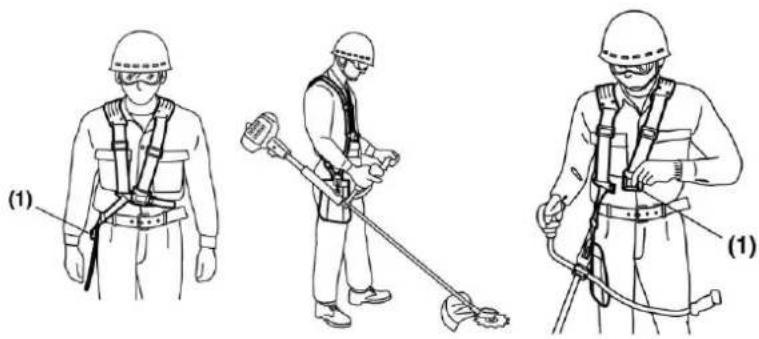
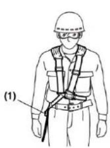
Always use the shoulder strap. Adjust and fix the belt and belt clamping plate on the machine so that the machine hangs a few cm above the floor.
The cut-out head and the protective shield should be aligned horizontally in all directions. Pre-tension the machines on the right side of your body.
WARNING

Additionally, wear head, eye, face, and hearing protection and shoes against smooth surfaces. Do not wear bars, jewelry, or loose, dangling clothes that could get caught in the machine. Do not wear footwear with unprotected toes and do not work barefoot or without leg protection. In certain situations, you must wear head protection.

natural_image
Worker in hard hat and safety gear handling equipment on a pole (no visible text or symbols)
natural_image
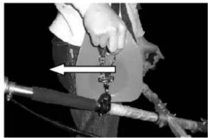
Line drawing of hands adjusting a belt buckle (no text or symbols)
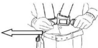
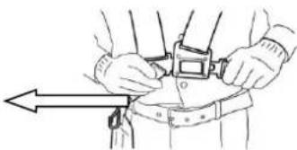
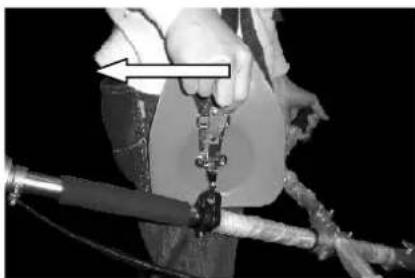
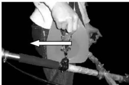
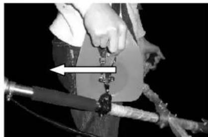
The shoulder strap is equipped with a quick-release device (see picture). You can quickly remove the shoulder strap by pulling the quick release.
Read the manual carefully. Be thoroughly familiar with the controls and correct use of the machine. Learn how to stop the machine and how to turn off the device. Understand how to stop and shut down the device. Understand how to release a clamped attachment quickly.
Do not allow anyone to use the machine without correct instructions. Be sure that the user wears a foot, leg, eye, face, and hearing protection. Keep the area clear of bystanders, children, and pets. Never allow children to operate or play with the machine.
Never allow anyone to enter the HAZARDOUS ZONE while working with you. The DANGER ZONE is an area with a radius of 15 meters (approximately 16 steps) or 50 feet. Insist that persons in the DANGER ZONE wear eye protection from thrown objects beyond the danger zone. If the machine is to be used where there are unprotected people, operate at a low, reduced speed to reduce the risk of an object thrown.
- Component overview

- SHEET (3-tooth)
- CUTTING KNIFES
- PROTECTIVE SHIELD
- DRIVE AXLE
- U-HANDLE
-
ASSISTANCE HANDLING
-
HAND HANDLE
- THROTTLE LOCK*
- ENGINE STOP SWITCH
- SAFETY INTERLOCK
- GAS LEVER
- TANK
- FUEL CAP
- CONNECTOR
- WING SCREW
- SHOULDER BELT
*8 GAS LEVER LOCK prevents accidental acceleration of the engine. The throttle stick can only be pressed when the throttle stick lock is pressed.
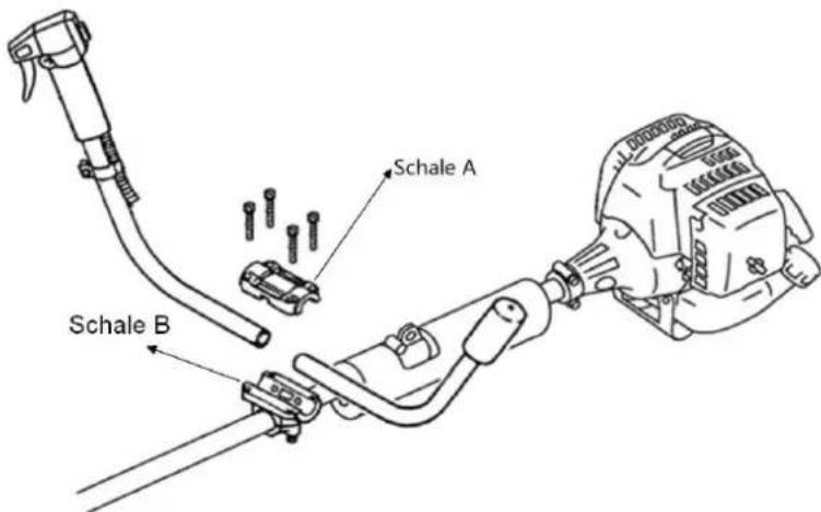
21. Mounting the motor scythe
Attaching the handle
The handle must be mounted before use.
For correct installation, follow the illustrations below.
Mounting the handle tube for use
Place cup B on the shaft tube, up and down, screw both cups and the shaft tube together.
Put the handle into the provided clamping bush, which is already attached to the shaft tube. Now place the other shell on top and screw both half-shells and the grip tube together. Please pay attention to the illustration "Components" to ensure that the handle is in the correct position!
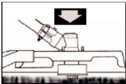
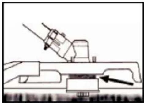
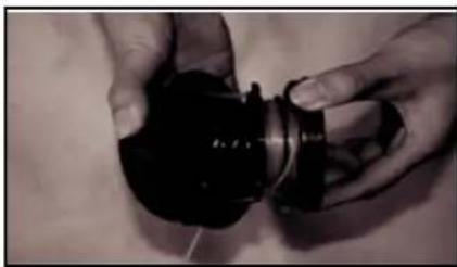
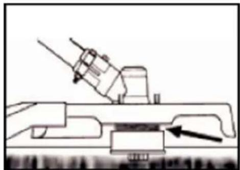
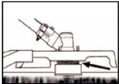
Mounting the drive axle
1). Place the drive axle against the main shaft so that the hole of the axle is aligned with the locking bolt of the connecting piece.
2). Actuate the locking pin and insert the drive axle into the main shaft. Release the locking pin and ensure that the locking pin engages in the hole.
3). Turn the wing screw clockwise to secure the connection.

natural_image
Close-up of a metallic mechanical clamp or bracket with a black base, no visible text or symbols

natural_image
Close-up of a hand holding a metallic cylindrical tool with a small inset component (no visible text or symbols)

natural_image
Hand holding a metal tool with a handle, against a plain white background (no text or symbols visible)
Installing the protective shield
Install the blade guard on the driveshaft tube against the gear housing. Tighten the holder of the guard so that the blade guard does not move or slide down during operation.

natural_image
Close-up of a mechanical tool with orange outline and black component, no visible text or symbols
Mounting the lawn trimmer
Step 1:
Insert the key (1) into the hole in the gear head so that the gear shaft is locked. Unscrew and remove the nut. Since it is a safety nut, please make sure that there is a left-hand thread here
Step 2:
mount the distance disk (2) and install the thread spool on the gear shaft. And then tighten it by hand.

Warning!
Make sure that all components are correctly assembled and installed and that all screws are tightened.
Installation of the protective shield
Install the protective shield on the driveshaft tube against the gear housing. Tighten the holder of the guard so that the blade guard does not move or slide down during operation.
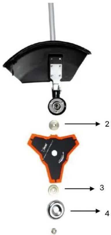
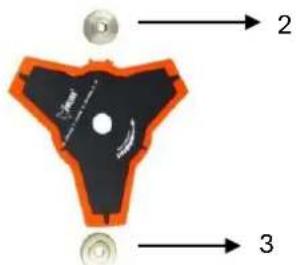
steps:
- Place the key (1) in the hole at the gear head.
- Remove the nut, the cover (4), and the upper distance disk (3) from the gear shaft
- Place the metal sheet on the lower distance disk (2). Make sure that the marked side of the cutting blade is in contact with the disc (2).
- Slide the upper distance disk (3) over the gear shaft on the metal sheet. Make sure the upper side of the cutting blade is in contact with the distance disk (3).
- Put on the cover (4) and screw the union nut tight with locked gear head (see point 1)

natural_image
Close-up of a mechanical tool with a black blade and orange base, being adjusted by hand (no text or symbols visible)

natural_image
Close-up of a black robotic brush with orange outline and mechanical lever (no text or symbols visible)

natural_image
Close-up of hands installing a mechanical component with a tool, no visible text or symbols
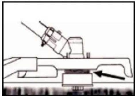
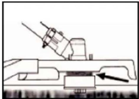
Check the oil level.
1 Place the engine horizontally on the floor.
2 Unscrew the dipstick and check the oil level, which should be up to the oil filler neck
3 If the oil level is too low, add the recommended oil up to the oil filler neck.
4 Close the oil cap.

WARNING

The capacity of the oil tank is 75ml.
Due to the low capacity, it is necessary to fill the oil slowly to avoid overflow and spillage.
Check the oil level every 10 working hours and top up if necessary

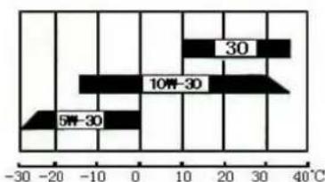
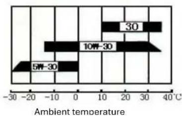
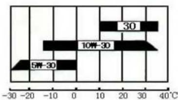
WARNING

We recommend the Oregon 4-stroke oil
or other brand oils
SAE 10W-30 in average ambient temperature.

natural_image
Close-up of a black and orange industrial machine with a green arrow pointing to its side (no text or symbols visible)

bar
| Temperature Range (°C) | Value |
|---|---|
| 30 | 30 |
| 10W-30 | 10W-30 |
| 5W-30 | 5W-30 |

WARNING

The use of 2 stroke oil is not allowed and reduces the life of the engine. The
recommended operating temperature is between -5^ and +40^
Recommended fuel
It is recommended to use unleaded gasoline with an octane number of 90 # or higher to reduce carbon deposition in the combustion chamber. Do not use old or dirty gasoline. Do not use a fuel mixture of engine oil and gasoline. Keep the fuel tank dust-free and avoid water getting into the tank. Sometimes misfiring will occur due to usual overload.
If the backfires are heard under the average load, we recommend changing the gasoline. If the misfire is still present afterward, please consult an authorized workshop.

WARNING
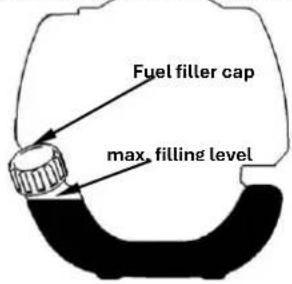
- Gasoline is highly flammable, and sparks can cause an explosion.
- Refuel only in well-ventilated rooms and let the engine cool down before filling. Smoking and open fire, as well as any sparks, must be avoided during refueling.
- Do not overfill the tank (the level should not be higher than the tank nozzle). After refueling, check that the tank cap is closed correctly.
- Avoid spilling any gasoline.
- Keep the machine away from children
Tank capacity: S35 (139F/P-B) 0.6L
Gasoline with an ethanol content
The engine can be operated with E10 gasoline. However, do not use gasoline with the higher ethanol content of 10%.
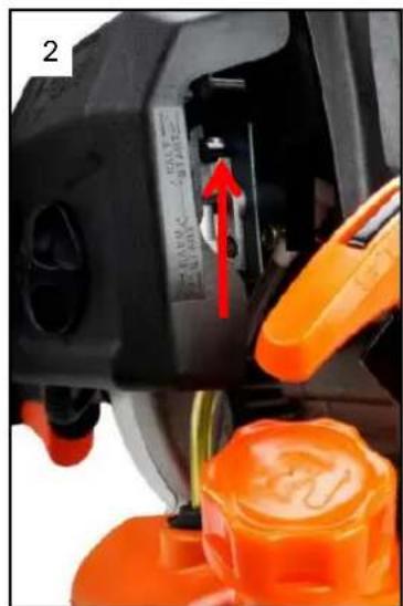
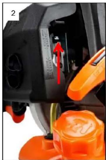
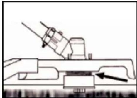
22. Cold start of the machine
- Place the device on a firm and flat surface.
Slide the engine stop switch down.

natural_image
Close-up of a black cylindrical device with an orange internal component and red directional arrows indicating movement (no text or symbols)

natural_image
Close-up of a mechanical device with orange and black components, showing a green arrow pointing to a component (no text or symbols visible)

natural_image
Close-up of a mechanical device with orange and black casing, showing internal components and a green arrow pointing to a component (no text or symbols visible)
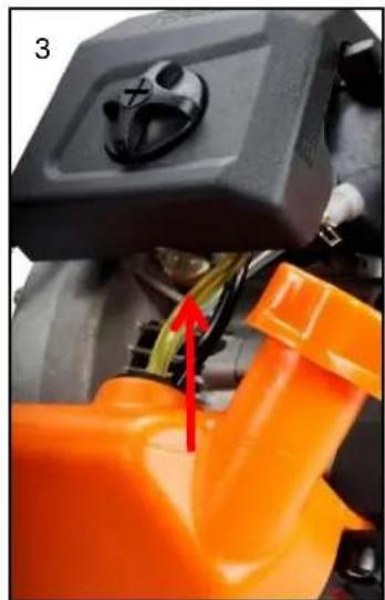
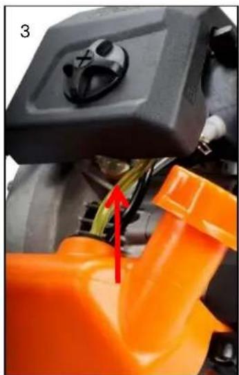
- Move the choke lever upwards to "COLD START."
-
Press the carburetor pump about 8-10 times (until gasoline flows in the line)
-
Pull out the starter rope with a short-stroke until resistance is felt
(about 100mm). A continuous, mainly fast train will provide a strong spark, and the engine will respond after 2-3 trains.
-
Important: After the engine has responded, return the choke lever to the "WARM START" position and immediately pull the starter again until the engine starts. Also, see the video "Device start" on our homepage.
-
Let the engine warm-up for about 10 minutes at idle

NOTE: If the machine does not start after repeated attempts, refer to troubleshooting chapters.
NOTE: Always pull the starter cord straight out. Pulling the starter at an angle will cause the rope to rub against the eyelet. Pulling the starter at an angle can cause the starter cord to fray or break.
Always hold the starter handle firmly when the rope pulls back. Never let the rope be thrown back from the pulled-out position. This could damage the starter device.
23. Warm start of the machine
- Place the device on a firm and flat surface.
- Move the engine stop switch down
- Slide the choke to the "WARM START" position
- Pull out the starter rope with a short-stroke until resistance is felt
(about 100mm). A continuous high-speed train will provide a strong spark and start the engine
If the machine does not start, please proceed again according to "Cold start of the machine
STOP MACHINE
Unlock the throttle lever. Let the machine return to idle. Push the engine stop switch until the machine stops.
ADDITIONAL SAFETY INSTRUCTIONS
Before running your machine, repeat GENERAL SAFETY INSTRUCTIONS in this manual.
CAUTION
IF YOU are NOT familiar with the trimming techniques, practice with the MACHINE in the "OFF" position.
ALWAYS TRIM OR CUT AT HIGH ENGINE SPEEDS. Do not run the machine slowly at the beginning or when trimming.
ALWAYS MAKE DISTANCE IN WORKING AREAS from cans, bottles, rocks, etc. Striking objects can cause serious injury to users or bystanders and can also damage the machine. If an object is accidentally struck, immediately stop the MACHINE and check the device. Never run the machine with damaged or defective parts.
DO NOT use the machine for any purpose other than trimming grass.
NEVER lift nylon cutting head above knee height when operating.
Do not run the machine on a slope if there is a chance of slipping or losing stability.
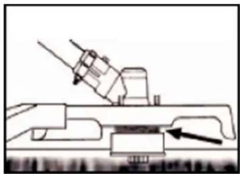
RELEASE OF THE NYLON CUTTING HEAD

To release fresh thread, leave the machine at full power and "push" on Run nylon cutting head against the lawn. The thread releases automatically. The
protective shield cuts off excess thread.

CAUTION: Remove grass deposits regularly to prevent overheating of the drive axle. Grass build-up occurs when weed fibers become entangled around the shaft under the protective shield. This condition prevents the shaft from cooling correctly. Remove grass deposits with a screwdriver or similar tool only when the machine is switched off.
natural_image
Technical line drawing of a mechanical assembly with a downward arrow indicating force or direction (no text or symbols present)
natural_image
Technical line drawing of a mechanical assembly with an arrow indicating a component (no text or symbols present)
24. Trimming techniques
When properly equipped with a protective shield and nylon cutting head, your machine will trim unsightly weeds and tall grass with extended reach and areas along fences, walls, land, and around trees.
NOTE: Pay special attention when trimming on brick or stone walls, etc., which will cause rapid weed wear.
TRIM MORE ACCURATELY
Swing the trimmer from side to side with a nylon cutting head. Do not tilt the nylon cutting head while working. For correct cutting height, trim in a test area beforehand. For right cutting height, trim in advance in a test area. Keep nylon cutting head at the same level for the uniform depth of the cut.
natural_image
Diagram of a mechanical device emitting particles or smoke, with arrows indicating direction (no text or symbols)
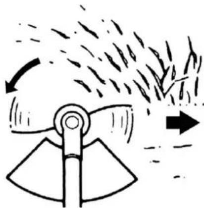
TRIMMING AROUND TREES
Trim around logs with a slow approach, so the thread does not contact the log. Walk around the tree from left to right. Approach grass or weeds with the tip of the thread and tilt the nylon cutter head slightly.
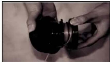
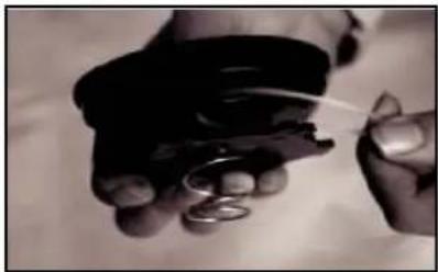
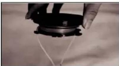
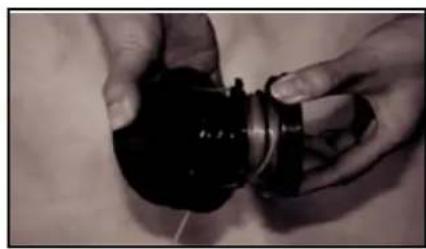
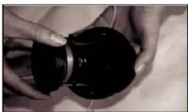
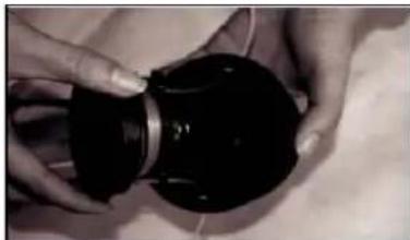
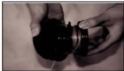
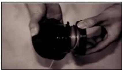
Replace nylon thread
- Switch off the engine.
- Place the trimmer on the floor so that the cutting tool is facing upwards with the bobbin.
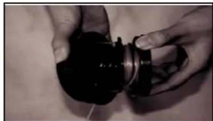
-
Open the cutting device and the spool by turning the locking knob on the shock absorber.
-
Cut the new thread to 6 or 5 meters and wind it tightly clockwise around the bobbin.
-
Remove the superfluous thread.
natural_image
Close-up of hands holding a small object with a white tool, no visible text or symbols
natural_image
Close-up of hands holding a black mechanical component (no visible text or symbols)
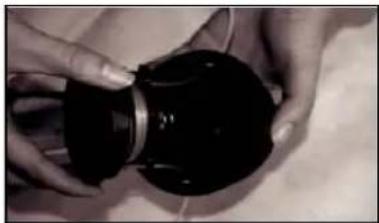
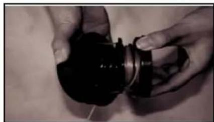
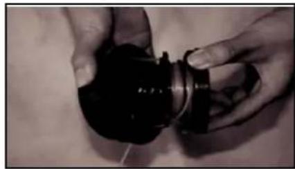
- After the bobbin is wrapped, fix the thread ends, as shown in the picture.
natural_image
Close-up of a hand holding a black mechanical component with wires, against a cloudy sky background (no text or symbols visible)

natural_image
Close-up of hands holding a black cylindrical object (no visible text or symbols)
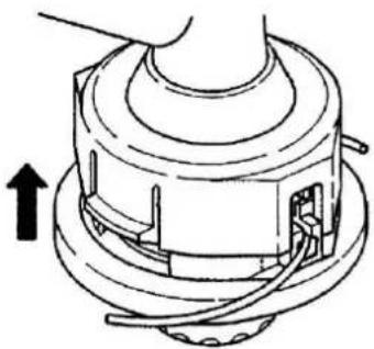
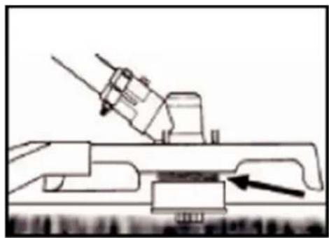
-
put the cord ends through the holes in the outer part of the bobbin.
-
Press the inner and the outer bobbin together and turn them against each other until they engage.
natural_image
Technical line drawing of a mechanical assembly with no visible text or symbols
25. Maintenance and care
Regular checks and adjustments must be made to ensure that the gasoline engine maintains its excellent performance. Periodic maintenance also provides a long service life. See the following table for the regular maintenance cycle.
| Component\Maintenancecycle | Everyuse | Everymonthor 10h | Every 3monthsor 25h | Every 6monthsor 50h | Every 12monthsor 100h | Every 2years or300h |
| Lubricatingoil | Check oil level | ■ | | | | | |
| Exchange | | ■ | | ■ | | |
| Air Filter | Check | ■ | | | | | |
Manual_FX-4MS142_Int24_rev2
| Clean up | | | ■a | | | |
| Spark plug | Check & adjust | | | | | ■ | |
| Exchange | | | | | | ■ |
| Spark plug connector (optional) | Clean up | | | | | ■ | |
| Cooling fins | Exam | | | | ■ | | |
| connecting elements such as screws and nuts | Check (tighten if necessary) | | | | | | |
| Coupling | Exam | | | | ■b | | |
| Idle speed | Check and adjust | | | | | ■b | |
| Valve clearance | Check and adjust | | | | | ■b | |
| combustion chamber | Clean up | 300 h thereafter |
| Fuel | Check | | | | | ■ | |
| Fuel tank | Check | | | | | ■ | |
| Fuel line | Check | Every x years (replace if necessary) |

WARNING
A. Increase maintenance intervals if working in dusty environments.
B. All maintenance work - except for the work listed in the operating instructions -
must be carried out by qualified maintenance personnel
C. For commercial use, maintenance cycles must be adjusted as required.
Oil change
It is also recommended to replace the oil if it runs hot and loses
its lubricating properties.
1 After filling, check that the oil cover is well closed.
2 When changing the oil, unscrew the oil cover and tilt the motor towards the oil filler neck to collect the oil in a suitable container for used oil.
3 Fill in sufficient new 4 cycle oil.
4 Screw the oil cover back in.
In case of spillage, please wipe off the overflowing oil and do not forget
to wash your hands well with soap.
WARNING

Please contact your local community for the disposal of the used oil. Please do not dispose of used oil in the sewage system or the open environment.
Maintenance
Air Filter
The function of the air filter is to clean impurities like dust from the air and to prevent these dust particles from entering the combustion chamber and the carburetor.
To avoid any damage to the carburetor, it is necessary to carry out regular maintenance of the air filter. The maintenance intervals must be increased when working in a dusty environment.
WARNING
Please do not use alcohol or highly flammable agents to clean the air filter, as this could lead to a fire or even an explosion
It is strictly forbidden to operate the engine without an air filter, as this would cause damage to the engine.
1 Turn the screw counterclockwise to remove the filter cover
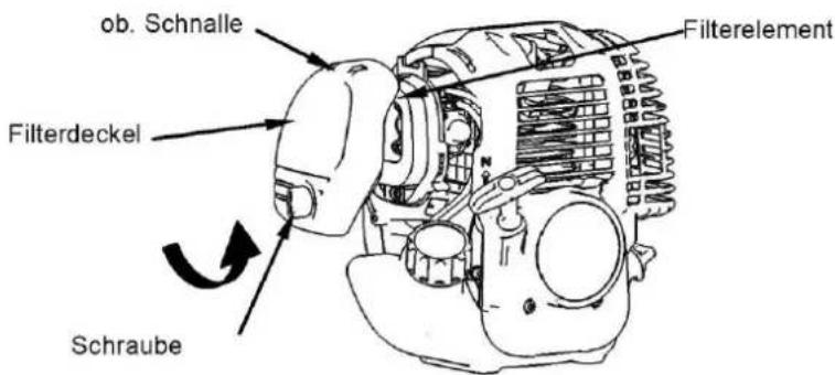
2 Use non-flammable solvents or cleaning agents with a high flash point to clean the filter element and let it dry completely.
3 Immerse the filter element in fresh lubricating oil and then press out the oil.
4 Put the filter element in the correct position again.
5 Install the filter cover and screw the screw back in clockwise.
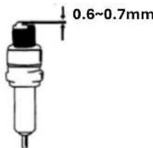
Spark plug maintenance
To ensure regular operation of the engine, the ignition distance of 0.6 - 0.7
must be maintained and free of carbon deposits.
1 Carefully remove the spark plug connector. Do not pull on the cable but directly on the plug.
2 Use the spark plug wrench supplied to unscrew the spark plug.
3 Visually check the spark plug for damage or electrode burn-off.
Remove the carbon deposits.
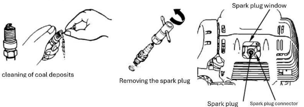
4 Check the gap with a feeler gauge and bend the electrode to the correct distance of 0.6 to 0.7mm
5 Check the spark plug washer and screw the spark plug in the first 2-3 threads manually first.
6 Mount the ignition cap back on the spark plug
WARNING

The spark plug must be screwed down tightly; otherwise, the engine runs hot and is damaged.
Maintenance during storage of the machine
If the engine is not to be used for a more extended period, the following maintenance must be carried out:
1 Open the fuel filler cap and drain the fuel completely. Operate the primary pump until the gasoline is completely removed from the fuel lines.
2 Open the oil cap and completely drain the lubricating oil as described
3 Adjust the crankshaft to top dead center (by pulling the starter) to ensure that the air does not cause corrosion
4 Wipe off all oil stains and clean the cooling fins. Place the device in a clean, dry, and well-ventilated place.
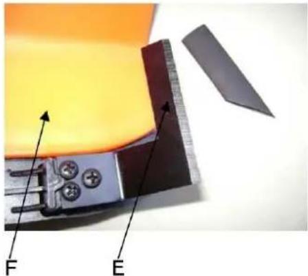
PROTECTIVE SHIELD-KNIFE SHARPENING.
- Remove the cutting blade (E) from the protective shield (F).
- Clamp the knife in a vice. Sharpen the knife with a flat-file.
Please make sure that you keep the angle of the cutting edge. Move the blade only in one direction.
natural_image
Close-up of a mechanical component with labeled parts F and E, showing internal components and a ruler-like structure (no readable text or symbols beyond labels)
STORAGE OF A MACHINE

WARNING: If these steps are not taken, plaque will form in the carburetor and cause difficult starting or permanent damage due to storage.
- Perform all general maintenance recommended in the maintenance section of your user manual.
- Clean the exterior of the machine, drive axle, protective shield, and nylon cutting head.
- Drain fuel from the fuel tank.
- After fuel is drained, start the machine.
- Let the device idle until the machine stops by itself. This cleans the carburetor of fuel.
- Let the machine cool down (about 5 minutes).
- Use a spark plug wrench, remove the spark plug.
- Pour 1 teaspoon of clean 2-cycle oil into the combustion chamber. Pull the starter cord slowly several times to coat the internal components. Replace the spark plug.
- Store the machine in a cool, dry place away from any ignition source such as an oil burner, water heater, etc.
TRANSPORT PROTECTION
Make sure that the machine is well visible during transport to avoid fuel loss, damage, or injury.
Use transport protection for metal sheets during transport and storage.
26. Troubleshooting
- Difficulties during commissioning
| Situation | Cause | Solution |
| No ignition spark | Spark plug | Coal deposit | Clean the spark plug.Adjust the gap0.6~0.7mm Replace the spark plug |
| other | ignition coil defective flywheel magnet too weak | replaced ignition coil replaced flywheel |
| Weak ignition spark | Compression | Too much gasoline in the combustion chamber Poor fuel or water in the tank | Remove the spark plug and allow it to dry.Replace fuel |
| The carburetor does not pump oil anymore. | Oil line blocked | Cleaning the carburetor and cleaning the pipes |
| regular oil supply but weak compression | Piston rings do not close spark plug not tightly screwed on Cylinder head, not tight Incorrect valve clearance or ignition timing. | replace screw tightReplace or adjust |
| regular oil supply and good ignition spark | Poor contact between ignition cap and spark plug Short circuit or on/off switch | replace or check |
- Emergencies during operation
| Situation | Cause | Solution |
| the engine does not reach the speed | Choke is in the wrong position. The exhaust system does not clog the air supply. Moving elements have worn ignition spark weakly too much valve clearance. Cylinder head sooty | Open choke Replace exhaust system Check or replace ignition coil, flywheel. Spark plug Adjust valves Clean cylinder head |
| Operating materials are leaking | Lines to carburetor blocked Spark plug spacing incorrect | Adjust replaced lines and carburetor gap |
| Engine noises | Wrong choke position Camshaft damaged | Check Replace camshaft |
| Carburetor leaking | Failure of the check valve on the tank cap | replaced the tank cap |
| The carburetor gasket is worn out | Replace carburetor or gasket |
If no troubleshooting solves the problem, contact your dealer.
27. Customer Service
Have your purchased device repaired only by qualified personnel and only with original spare parts. This will ensure that the safety of the device is maintained.
If you do not have the addresses of authorized service centers, please contact the sales office where you purchased the device. Please contact the manufacturer FUXTEC GmbH directly at www.fuxtec.de at any time regarding maintenance work and procurement of spare parts.
28. Warranty
The warranty period is 24 months from the date of purchase. Please keep your proof of purchase in a safe place. Excluded from the warranty are wearing parts and damage caused by improper use, use of force, technical modifications, use of wrong accessories or non-original spare parts, and repair attempts by non-qualified personnel. Authorized dealers may only carry out warranty repairs.
29. Disposal note
Please contact your local community for the disposal of the device. Please dispose of all functional materials such as gasoline and oil in advance.
- EU Declaration of Conformity
| Herewith we | FUXTEC GMBH |
| We herewith declare, | KAPPSTRAße 69, 71083 HERRENBERG, GERMANY |
| Declare that the machine described below, due to its design and construction and in the version marketed by us, complies with the relevant essential health and safety requirements of the EC directives. |
| That the following machine complies with the appropriate basic safety and health requirements of the EC Directive based on its design and type, as brought into circulation by us. |
| This declaration becomes invalid if the machine is modified without our agreement. |
| In case of alteration of the machine, not agreed upon by us, this declaration will lose its validity |
| Designation of the machine: | Gasoline motor scythe/lawn trimmer |
Machine Description:
Machine Type:
Trade name
| Power consumption/capacity | 42,5cm ^3 |
| Measured sound power level Measured sound | LPA =104dB |
power level
| Guaranteed sound power level: Guaranteed | LWA=113dB |
sound power level
| Relevant EG-straightening thread: | EC machine straightening thread 2006/42/EG |
Applicable EC Directives: EC Machinery Directive: 2006/42/EC
EC Directive on Electromagnetic Compatibility (EMC) 2004/108/EC
EC Directive of Electromagnetic Compatibility 2004/108/EC
EC-directive thread Noise emission (2000/14/EWG & 2005/88/EC)
EC Directive of noise emission (2000/14/EC & 2005/88/EC)
| applied harmonized | EN 11806-1 |
Applicable Harmonized Standards:
Manufacturer signature/date:
Authorized Signature/Date/ Place:

L. Zirkler, 07.06.2023
The name and address of the person
authorized to compile the technical Leonhard Zirkler
documentation established within the FUXTEC GMBH - KAPPSTRAße 69, 71083 HERRENBERG, GERMANY
community
Name and address of the person authorized to
compile the technical file, which must be
established in the
VERSION FRANCAISE
MODE D'EMPLOI ORIGINAL
natural_image
Exterior view of a small manual tool with a black-and-orange brush and orange handle (no text or symbols visible)
CE
natural_image
Line drawing of a person wearing a helmet and safety harness, holding equipment (no text or symbols)

natural_image
Line drawing of a worker in safety gear using a tool (no text or symbols)

natural_image
Illustration of a person wearing a full-body safety harness and helmet, holding equipment (no text or symbols)
natural_image
Line drawing of hands adjusting a device with an arrow indicating left motion (no text or symbols)
natural_image
Person holding a mechanical device with attached cable (no visible text or symbols)
natural_image
Close-up of a metallic mechanical clamp or bracket with a black base, next to a cylindrical rod (no text or symbols visible)

natural_image
Hand holding a metallic cylindrical tool with a dial indicator (no visible text or symbols)

natural_image
Hand holding a metal tool with a handle, against a plain white background (no text or symbols visible)
natural_image
Close-up of a black robotic brush with orange outline and mechanical lever (no text or symbols visible)
natural_image
Three black arrows labeled 1, 2, and an unlabeled curved arrow pointing upward (no text or symbols beyond labels)
Avertissement !
natural_image
Close-up of a black handheld device with orange outline and mechanical lever (no visible text or symbols)

natural_image
Two-step diagram showing a tool being inserted into a mechanical component, with no visible text or symbols.
natural_image
Close-up of a mechanical engine with black and orange components, no visible text or symbols
natural_image
Close-up of a black handheld device with an orange internal component and a red arrow indicating direction (no text or symbols)
natural_image
Close-up of a mechanical component with orange and black parts, no visible text or symbols
natural_image
Close-up of a Fuxtev electric motor with attached fan and propeller (no visible text or symbols)
natural_image
Technical line drawing of a mechanical device with a downward arrow indicator (no text or symbols present)
natural_image
Technical line drawing of a mechanical assembly with a tool and component (no text or symbols)
natural_image
Diagram of a mechanical device emitting particles with motion arrows indicating flow (no text or symbols)
COUPER AUTOUR DES ARBRES
natural_image
Close-up of hands holding a small mechanical component with a wire, no visible text or symbols
natural_image
Close-up of hands holding a black mechanical component (no visible text or symbols)
natural_image
Close-up of a hand holding a black mechanical component with wires, no visible text or symbols

natural_image
Close-up of hands holding a black cylindrical object (no visible text or symbols)
AVERTISSEMENT
natural_image
Close-up of a mechanical component with labeled parts F and E, showing yellow material and a ruler-like structure (no text or symbols beyond labels)
STOCKAGE D'UN APPAREIL

EC Declaration of Conformity
We herewith declare,
KAPPSTRAße 69, 71083 HERRENBERG, GERMANY
that the following machine complies with the appropriate basic safety and health requirements of the EC Directive based on its design and type, as brought into circulation by us.
In case of alteration of the machine, not agreed upon by us, this declaration will lose its validity
Machine Description:
Type d'appareil :
FX-4MS142
Machine Type:
Measured sound power level
Puissance
LPA = 104dB
sonore mesurée
Guaranteed sound power level:
Puissance
L_WA=113dB
sonore garantie
Directives CE applicables :
Directive Machines 2006/42/CE
Applicable EC Directives:
EC Machinery Directive: 2006/42/EC
EC Directive of Electromagnetic Compatibility 2004/108/EG
EC Directive of noise emission (2000/14/EC & 2005/88/EC)
Applicable Harmonized Standards:
EN ISO 14982
Authorized Signature/Date/ Place:
C. Bille
L. Zirkler, 07.06.2023
name and address of the person authorised to
compile the technical file, who must be
established in the Community
VERSIONE ITALIANA
natural_image
Exterior view of a manual tool with a black-and-white body, extending from a metal rod (no text or symbols visible)
natural_image
Close-up of a person using a mechanical tool to lift or lift a cylindrical object, with no visible text or symbols.
natural_image
Close-up of a metallic mechanical clamp or bracket with a black base, no visible text or symbols

natural_image
Hand holding a metallic cylindrical tool with a knob, against a white background (no text or symbols visible)

natural_image
Hand holding a metallic tool with a handle, against a plain white background (no text or symbols visible)
natural_image
Close-up of a black handheld device with orange outline and mechanical lever (no visible text or symbols)
natural_image
Close-up of a black handheld device with orange frame and mechanical lever (no visible text or symbols)

natural_image
Two-step diagram showing a tool being inserted into a mechanical component, with no visible text or symbols.
natural_image
Close-up of a black mechanical device with orange internal components and a red arrow indicating a downward motion (no text or symbols)
natural_image
Close-up of a mechanical component with orange and black parts, showing a red arrow pointing to a green cable or wire (no text or symbols visible)
natural_image
Technical line drawing of a mechanical device with a downward arrow indicator (no text or symbols present)

natural_image
Technical line drawing of a mechanical assembly with a tool and base component (no text or symbols)
natural_image
Diagram of a mechanical device emitting smoke or vapor, with arrows indicating direction (no text or symbols)
TAGLIARE INTORNO GLI ALBERI
natural_image
Close-up of hands holding a black mechanical component with wires, no visible text or symbols

natural_image
Close-up of hands holding a black cylindrical object (no visible text or symbols)
natural_image
Technical line drawing of a mechanical assembly with no visible text or symbols
natural_image
Close-up of a mechanical component with labeled parts F and E, showing internal components and a ruler (no readable text or symbols beyond labels)
IMMAGAZZINAGGIO DI UNA DISPOSITIVO

We herewith declare,
KAPPSTRAße 69, 71083 HERRENBERG, GERMANY
that the following machine complies with the appropriate basic safety and health requirements of the EC Directive based on its design and type, as brought into circulation by us.
In case of alteration of the machine, not agreed upon by us, this declaration will lose its validity
Machine Description:
Applicable EC Directives:
EC Machinery Directive: 2006/42/EC
EC Directive of Electromagnetic Compatibility 2004/108/EG
EC Directive of noise emission (2000/14/EC & 2005/88/EC)
Applicable Harmonized Standards:
EN ISO 14982
Authorized Signature/Date/ Place:
C. Bille
L. Zirkler, 07.06.2023
the person authorised to compile the technical
file, who must be established in the
Community
VERSION ESPANOLA
natural_image
Model of a manual tool with a black-and-white brush and orange handle, extending diagonally (no text or symbols visible)
CE
MANTÉNGASE SIEMPRE A 15 METROS DE DISTANCIA DE OTRA PERSONA
DISTANCIA
EL NIVEL DE RUIDO GARANTIZADO CUMPLE CON LAS DIRECTRICES LEGALES SOBRE RUIDO

natural_image
Close-up of hands operating a mechanical device with a lever and connecting rod (no visible text or symbols)
- CUCHILLA (3 dientes)
- CUCHILLAS DE CORTE
- ESCUDO
- EJE MOTRICE
- MANIJA EN U
- EMPUÑADURA AUXILIAR
- ASA
- BARRERA DE GASES*
- INTERRUPTOR DE PARADA DEL MOTOR
- ENCLAVAMIENTO DE SEGURIDAD
- ESTRANGULAR
- TANQUE
- TAPÓN DE COMBUSTIBLE
- ENLACE
- TORNILLO DE ALA
- CORREA PARA EL HOMBRO
natural_image
Close-up of a metallic mechanical clamp or lever mechanism with a black base (no text or symbols visible)

natural_image
Hand holding a metallic cylindrical tool with a measuring tape (no visible text or symbols)

natural_image
Hand holding a metallic tool with a handle, against a plain background (no text or symbols visible)
natural_image
Close-up of a black and orange robotic brush tool with a lever handle (no text or symbols visible)
natural_image
Close-up of a black robotic brush with orange outline and mechanical lever (no text or symbols visible)

natural_image
Two-step diagram showing a tool being inserted into a mechanical component, with no visible text or symbols.
natural_image
Close-up of a black and orange electric shaver with a green arrow indicating direction (no text or symbols)

ADVERTENCIA

natural_image
Close-up of a black handheld device with orange buttons and a red arrow indicating direction (no text or symbols)

natural_image
Close-up of a mechanical device with orange and black components, showing a green arrow pointing to a component (no text or symbols visible)

natural_image
Close-up of a mechanical device with orange and black components, showing a green arrow pointing to a component (no text or symbols visible)
natural_image
Close-up of a mechanical device with orange and black components, showing internal wiring and directional arrows (no text or symbols)
natural_image
Technical line drawing of a mechanical assembly with a downward arrow indicating force or direction (no text or symbols present)
natural_image
Technical line drawing of a mechanical assembly with an arrow indicating a component (no text or symbols present)
natural_image
Diagram of a mechanical device emitting particles or smoke, with arrows indicating direction (no text or symbols)
natural_image
Close-up of hands holding a small object with a white tool, possibly a tool or device (no visible text or symbols)
natural_image
Close-up of hands holding a black mechanical component (no visible text or symbols)
natural_image
Close-up of a hand holding a black mechanical component with wires, against a cloudy sky background (no text or symbols visible)
natural_image
Close-up of hands holding a black cylindrical object with a circular top (no visible text or symbols)
natural_image
Technical line drawing of a mechanical assembly with no visible text or symbols
natural_image
Illustration of hands performing a manual tooling process with a spark plug (no text or symbols present)
natural_image
Technical line drawing of a mechanical device with no visible text or symbols
ADVERTENCIA

natural_image
Close-up of a mechanical component with labeled parts F and E, showing internal components and a ruler-like scale (no text or symbols beyond labels)
ALMACENAMIENTO DE UNA MÁQUINA

natural_image
Exterior view of a manual tool with a black-and-white body, no visible text or symbols
CE
MANTENHA SEMPRE A 15 METROS DE DISTÂNCIA DE OUTRA
PESSOA
DISTÂNCIA

O NÍVEL DE RUÍDO GARANTIDO ESTÁ EM CONFORMIDADE COM AS DIRETRIZES LEGAIS DE RUÍDO

natural_image
Close-up of a person using a mechanical tool to adjust or install a cylindrical component, with no visible text or symbols.
-
LÂMINA (3 dentes)
-
LÂMINAS DE CORTE
-
ESCUDO
-
EIXO MOTOR
-
PUNHO EM U
-
PEGA AUXILIAR
-
PEGA
-
BARREIRA DE GÁS*
-
INTERRUPTOR DE PARAGEM DO MOTOR
-
INTERTRAVAMENTO DE SEGURANÇA
-
ACELERADOR
-
TANQUE
-
TAMPA DE COMBUSTÍVEL
-
LIGAÇÃO
-
PARAFUSO DE ASA
-
TIRA DE OMBRO
natural_image
Close-up of a metallic mechanical clamp or bracket with a black base and circular end (no text or symbols visible)

natural_image
Close-up of a hand holding a metallic cylindrical tool with a knob (no visible text or symbols)

natural_image
Hand holding a mechanical tool with a metallic handle and black grip (no text or symbols visible)
natural_image
Close-up of a black and orange robotic brush tool with a lever handle (no text or symbols visible)
natural_image
Close-up of a black robotic brush with orange outline and mechanical lever (no text or symbols visible)

natural_image
Two-step diagram showing a tool being inserted into a mechanical component, with no visible text or symbols.
natural_image
Close-up of a black and orange portable air purifier with a green arrow indicating direction (no text or symbols)

ADVERTÊNCIA

natural_image
Close-up of a black handheld device with orange buttons and a red arrow indicating a downward motion (no text or symbols)

natural_image
Close-up of a mechanical device with orange and black components, showing a green arrow pointing to a component (no text or symbols visible)

natural_image
Close-up of a mechanical device with orange and black casing, showing internal components and a green arrow pointing to a component (no text or symbols visible)
natural_image
Close-up of a mechanical device with orange and black components, showing internal wiring and directional arrows (no text or symbols)
natural_image
Technical line drawing of a mechanical device with a downward arrow indicator (no text or symbols present)
natural_image
Technical line drawing of a mechanical assembly with a tool and component (no text or symbols)
natural_image
Diagram of a mechanical device emitting smoke or vapor, with arrows indicating direction (no text or symbols)
do corte.
CORTE EM TORNO DE ÁRVORES
natural_image
Close-up of hands holding a small mechanical component with a wire, no visible text or symbols
natural_image
Close-up of hands holding a black mechanical component (no visible text or symbols)
natural_image
Close-up of a hand holding a black mechanical component with wires, against a cloudy sky background (no text or symbols visible)
natural_image
Close-up of hands holding a black cylindrical object (no visible text or symbols)
natural_image
Technical line drawing of a mechanical component with no visible text or symbols
natural_image
Illustration of a hand pouring liquid into a screwdriver (no text or symbols)
natural_image
Line drawing of a mechanical component with a curved arrow indicating rotation (no text or symbols)
Remoção da vela de
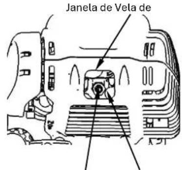
Vela de
Conector de Vela de
ignicão
natural_image
Close-up of a mechanical component with labeled parts F and E, showing internal components and a cutting tool (no text or symbols beyond labels)
ARMAZENANDO UMA MÁQUINA

natural_image
Model of a manual tool with a black-and-white body, extending from a metal rod (no visible text or symbols)
CE
HET AANRAKEN VAN HET DRAAIENDE MES IS VERBODEN, LETSEL

HOUD ALTIJD 15 METER AFSTAND VAN ANDERE PERSONEN AFSTAND

HET GEGARANDEERDE GELUIDSNIVEAU VOLDOET AAN DE
WETTELIJKE RICHTLIJNEN VOOR GELUID

WAARSCHUWING VOOR RONDVLIEGENDE VOORWERPEN
NIET ROKEN EN OPEN VUUR OP HET APPARAAT
natural_image
Close-up of a person using a mechanical device with a lever mechanism (no visible text or symbols)
- BLAD (3-tands)
- SNIJMESSEN
- SCHILD
- AANDRIJFAS
- U-HANDGREEP
- EXTRA HANDVAT
- HANDVAT
- GASBARRIÈRE*
- MOTORSTOPSCHAKELAAR
- VEILIGHEIDS VERGRENDELING
- WURGEN
- TANK
- TANKDOP
- VERBINDEN
- VLEUGEL SCHROEF
- SCHOUDERRIEM
natural_image
Close-up of a metallic mechanical clamp or bracket with a black base and circular end (no text or symbols visible)

natural_image
Close-up of a hand holding a metallic cylindrical tool with a knob (no visible text or symbols)

natural_image
Hand holding a metallic tool with a handle, against a plain white background (no text or symbols visible)
natural_image
Close-up of a black robotic brush with orange outline and mechanical lever (no text or symbols visible)
natural_image
Close-up of a black handheld device with orange frame and mechanical lever (no visible text or symbols)


natural_image
Close-up of a mechanical tool with a black blade and orange base, being adjusted by hand (no text or symbols visible)

natural_image
Close-up of hands installing a mechanical component with a wrench, no visible text or symbols
natural_image
Close-up of a black and orange electric shaver with a green arrow indicating motion (no text or symbols)

WAARSCHUWING

natural_image
Close-up of a black handheld device with orange buttons and a red arrow indicating a downward motion (no text or symbols)

natural_image
Close-up of a mechanical device with orange and black components, showing a green arrow pointing to a component (no text or symbols visible)

natural_image
Close-up of a mechanical device with orange and black components, showing a green arrow pointing to a component (no text or symbols visible)
natural_image
Close-up of a mechanical device with orange and black casing, showing internal wiring and directional arrows (no text or symbols)
stationair draait
natural_image
Diagram of a naval gun firing from a ship deck, showing blade and gear assembly (no text or symbols)
natural_image
Technical line drawing of a mechanical assembly with no visible text or symbols
natural_image
Diagram of a mechanical device emitting smoke or vapor, with arrows indicating direction (no text or symbols)
SNOEIEN ROND BOMEN
natural_image
Close-up of hands holding a small black object with a coiled spring, no visible text or symbols
natural_image
Close-up of hands holding a black mechanical component (no visible text or symbols)
natural_image
Close-up of a hand holding a black mechanical component with wires extending upward (no visible text or symbols)

natural_image
Close-up of hands holding a black cylindrical object (no visible text or symbols)
natural_image
Technical line drawing of a mechanical assembly with no visible text or symbols
WAARSCHUWING

natural_image
Close-up of a mechanical component with labeled parts F and E, showing internal components and a ruler-like structure (no readable text or symbols beyond labels)
BESCHERMING TEGEN TRANSPORT
natural_image
Exterior view of a manual tool with a black-and-white body, no visible text or symbols
CE
HÄLL ALLTID 15 METERS AVSTÅND FRÅN EN ANNAN PERSON AVSTÅND

DEN GARANTERADE LJUDNIVÅN ÖVERENSSTÄMMER MED DE
LAGSTADGADE BULLERRIKTLINJERNA

WARNING FÖR FLYGANDE FÖREMÅL

INGEN RÖKNING OCH ÖPPEN ELD PÅ ENHETEN
- BLAD (3-tandad)
-
SKÄRANDE BLAD
-
SKÖLD
- DRIVAXEL
- U-HANDTAG
- EXTRA HANDTAG
- HANDTAG
- GASBARRIÄR*
- STRÖMBRYTARE FÖR MOTORSTOPP
- SÄKERHETSSPÄRR
- STRYPVENTIL
- STRIDSVAGN
- TANKLOCK
- LÄNK
- VINGSKRUV
- AXELREM
natural_image
Close-up of a metallic mechanical clamp or bracket with a black base, no visible text or symbols

natural_image
Close-up of a hand holding a metallic cylindrical tool or mechanical component (no visible text or symbols)

natural_image
Hand holding a tool with a metallic handle and black clip, against a plain white background (no text or symbols visible)
natural_image
Close-up of a black electric shaver with orange outline and mechanical lever (no text or symbols visible)
Varning!
natural_image
Close-up of a black robotic brush with orange outline and mechanical lever (no text or symbols visible)

natural_image
Close-up of a black industrial fan or support structure with a metallic wheel and metal bracket (no text or symbols visible)

natural_image
Close-up of a mechanical tool with a black blade and orange base, being adjusted by hand (no text or symbols visible)

natural_image
Close-up of hands installing a mechanical component with a wrench, no visible text or symbols
natural_image
Close-up of a black and orange portable air purifier with a green arrow indicating direction (no text or symbols)

bar
| 材料 | 数值 |
|---|---|
| 5件-30 | -20 |
| 10件-30 | -10 |
| 30 | 30 |
-30℃, 40℃
Umgebungstemperatur

WARNING

natural_image
Close-up of a black cylindrical device with an orange internal component and a red arrow indicating direction (no text or symbols)

natural_image
Close-up of a mechanical device with orange and black components, showing a green arrow pointing to a component (no text or symbols visible)

natural_image
Close-up of a mechanical device with orange and black components, showing internal wiring and a green arrow pointing to a component (no text or symbols visible)
natural_image
Technical line drawing of a naval gun firing, showing blade and gear assembly (no text or symbols)
natural_image
Technical line drawing of a mechanical assembly with no visible text or symbols
natural_image
Diagram of a mechanical device emitting particles or smoke, with no visible text or symbols
BESKÄRNING RUNT TRÄD
natural_image
Close-up of hands holding a small object with a white plastic clip, no visible text or symbols
natural_image
Close-up of hands holding a black mechanical component (no visible text or symbols)
natural_image
Close-up of a hand holding a black mechanical component with wires, against a cloudy sky background (no text or symbols visible)

natural_image
Close-up of hands holding a black cylindrical object (no visible text or symbols)
natural_image
Technical line drawing of a mechanical component with no visible text or symbols
WARNING

natural_image
Close-up of a mechanical component with labeled parts F and E, showing internal components and a ruler-like structure (no readable text or symbols beyond labels)
FÖRVARING AV EN MASKIN

POLSKA WERSJA JEZYKOWA
ORYGINALNA INSTRUKCJA OBSŁUGI
natural_image
Exterior view of a manual tool with a black-and-white body, no visible text or symbols
CE
NOSIĆ RĘKAWICE (Ostra krawędź!).

ZAWSZE ZACHOWUJ ODLEGŁOŚĆ 15 METRÓW OD INNEJ OSOBY ODLEGŁOŚĆ

GWARANTOWANY POZIOM HAŁASU JEST ZGODNY Z PRAWNYMI
WYTYCZNYMI DOTYCZĄCYMI HAŁASU

natural_image
Close-up of a person using a mechanical tool to adjust or install a cylindrical component (no visible text or symbols)
- OSTRZE (3-zębne)
- OSTRZA
- TARCZA
- OŚ NAPEDOWA
- UCHWYT W KSZTAŁCIE LITERY U
- UCHWYT POMOCNICZY
- UCHWYT
- BARIERA GAZOWA*
- WYŁĄCZNIK SILNIKA
- BLOKADA BEZPIECZEŃSTWA
- PRZEPUSTNICA
- CZOŁG
- KOREK WLEWU PALIWA
- ŁĄCZE
- ŚRUBA SKRZYDŁA
- NARAMIENNIK
natural_image
Close-up of a metallic mechanical clamp or bracket with a black base, no visible text or symbols

natural_image
Close-up of a hand holding a metallic cylindrical tool or mechanical component (no visible text or symbols)

natural_image
Hand holding a metal tool with a handle, against a plain white background (no text or symbols visible)
natural_image
Close-up of a black robotic brush with orange outline and mechanical lever (no text or symbols visible)
Montaż Rasentrmerów
Krok 1:
natural_image
Close-up of a black robotic brush with orange outline and mechanical lever (no text or symbols visible)

natural_image
Two-step diagram showing a tool being inserted into a mechanical component, with no visible text or symbols.
natural_image
Close-up of a black and orange portable air purifier with a green arrow indicating motion (no text or symbols)

natural_image
Close-up of a black cylindrical device with orange internal components and a red arrow indicating direction (no text or symbols)

natural_image
Close-up of a mechanical device with orange and black components, showing a green arrow pointing to a component (no text or symbols visible)

natural_image
Close-up of a mechanical device with orange and black components, showing a green arrow pointing to a component (no text or symbols visible)
natural_image
Close-up of a mechanical device with orange and black components, showing internal wiring and directional arrows (no text or symbols)
natural_image
Illustration of a naval gun firing from a ship deck, with no visible text or symbols
natural_image
Technical line drawing of a mechanical assembly with an arrow indicating a component (no text or symbols present)
natural_image
Diagram of a mechanical device emitting particles or smoke, with arrows indicating direction (no text or symbols)
PRZYCINANIE WOKÓŁ DRZEW
natural_image
Close-up of hands holding a small object with a white tool, possibly a tool or device (no visible text or symbols)
natural_image
Close-up of hands holding a black mechanical component (no visible text or symbols)
natural_image
Close-up of a hand holding a black mechanical component with wires wrapped around it (no visible text or symbols)

natural_image
Close-up of hands holding a black cylindrical object (no visible text or symbols)
natural_image
Technical line drawing of a mechanical assembly with no visible text or symbols
natural_image
Illustration of a hand pouring liquid into a screwdriver (no text or symbols)
natural_image
Mechanical component diagram showing a shaft and housing assembly with a curved arrow indicating rotation (no text or symbols)
Wyjmowanie świecy
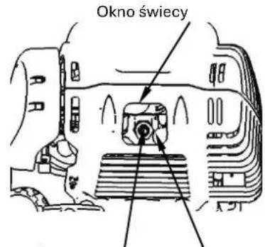
OSTRZEŻENIE

natural_image
Close-up of a mechanical component with labeled parts F and E, showing internal components and a ruler-like structure (no readable text or symbols beyond labels)
PRZECHOWYWANIE MASZYNY