FX-BV240 - Scarifier Fuxtec - Free user manual and instructions
Find the device manual for free FX-BV240 Fuxtec in PDF.
| Product Type | Gasoline Scarifier |
| Brand | Fuxtec |
| Model | FX-BV240 |
| Engine | 212 cm³, 4.1 kW at 3400 rpm |
| Fuel Tank Capacity | 3.6 L |
| Engine Oil Volume | 0.6 L |
| Cutting Width | 400 mm |
| Blades and Tines | 18 blades, 24 tines |
| Cutting Depth | -15 mm to +5 mm (below and above ground) |
| Wheel Size (front/rear) | 8 inches / 8 inches |
| Collection Bag Capacity | 45 L |
| Estimated Weight | ~30 kg |
| Approximate Dimensions (L x W x H) | ~100 x 50 x 80 cm |
| Power Source | Unleaded gasoline (95+ octane) |
| Main Functions | Scarification, aeration (with optional roller) |
| Height Adjustment | Center lever, continuous positions from -3 to -15 mm |
| Maintenance and Cleaning | Air filter cleaning every 25 h, engine oil change, spark plug cleaning |
| Spare Parts and Repairability | Rollers, blades, spark plugs, filters, brake pads (original parts) |
| Safety | Engine brake, emergency stop, debris guard, PPE required |
| General Information | Private use, max 10 h/year, for garden lawns |
Frequently Asked Questions - FX-BV240 Fuxtec
User questions about FX-BV240 Fuxtec
0 question about this device. Answer the ones you know or ask your own.
Ask a new question about this device
Download the instructions for your Scarifier in PDF format for free! Find your manual FX-BV240 - Fuxtec and take your electronic device back in hand. On this page are published all the documents necessary for the use of your device. FX-BV240 by Fuxtec.
USER MANUAL FX-BV240 Fuxtec
natural_image
Illustration of a yellow and black lawn mower with open blade, no text or symbols present
natural_image
Orange icon of a person reading a book (no text or symbols)
Manual\_FX-BV240\_Int24\_rev02
Inhalt
DEUTSCHE VERSION....8
ENGLISH VERSION....31
VERSION FRANCAISE....51
VERSIONE ITALIANA....73
VERSION ESPANOLA 94
VERSAO PORTUGUESA 115
NEDERLANDSE VERSIE ....138
SVENSK VERSION....161
POLSKA WERSJA JEZYKOWA 184
Inhalt
DEUTSCHE VERSION....8
text_image
Warning sign with triangular warning symbol, downward arrow indicating safety hazard, and three symbols: building, hazard, and crossbones.natural_image
Close-up of two circular objects on a dark surface, labeled 1 and 2 with an arrow pointing to one (no text or symbols beyond labels)Abb.3A
MONTAGE UND DEMONTAGE DES GRASFANGKORBS
natural_image
Close-up of a black electronic device with wires and a tool, no visible text or symbolsAbb. 4A

natural_image
Close-up of hands operating a mechanical device with a tool, no visible text or symbolsAbb. 4B
natural_image
Close-up of a black plastic panel with curved cutouts, mounted on a metal bracket (no visible text or symbols)Abb. 4C
ANLASSER
natural_image
Person cleaning a car window with a tool (no visible text or symbols)Abb.5
SCHNITTTIEFE
natural_image
Close-up of a hand operating a black cylindrical device on a metallic workbench (no visible text or symbols)Abb. 6
natural_image
Close-up of a motorcycle's front wheel with a circular dial indicator and arrow pointing to the wheel (no visible text or symbols)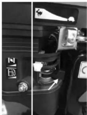
natural_image
Side-by-side comparison of a car interior showing the front and side views of a vehicle (no visible text or symbols)
natural_image
Person handling a black device with wires, possibly a vehicle or equipment item (no visible text or symbols)Fig.7D Fig.7E

natural_image
Close-up of a mechanical assembly with no visible text or symbolsZUM STOPPEN DES MOTORS

natural_image
Close-up of a hand holding a cable with a white arrow pointing to a component, placed on a textured surface (no visible text or symbols)Abb.8A Abb.8B
natural_image
Close-up of a black industrial component with a circular dial and directional arrow, no visible text or symbols.GRASFANGBEHÄLTER
natural_image
Close-up of a black plastic enclosure with visible internal components and mounting brackets, placed on a textured floor (no text or symbols)Abb.9A Abb.9B

natural_image
Close-up of hands holding a tool on a dark surface, possibly a musical instrument or electronic device (no visible text or symbols)natural_image
Close-up of a small wheeled vehicle with visible wheels and suspension components (no text or symbols)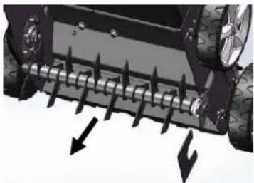
natural_image
Close-up of a vehicle's wheel rim with directional arrows indicating force or movement (no text or symbols)Abb.11A Abb.11B
natural_image
Close-up of a vehicle's wheel rim with visible tire tracks and mechanical components (no text or symbols)Abb.11C
Abb.11D

natural_image
Mechanical assembly diagram showing a shaft and wheel with an arrow indicating direction (no text or symbols)Abb.11E

natural_image
Close-up of a mechanical roller or spring assembly with no visible text or symbols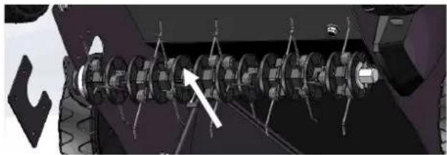
natural_image
Mechanical assembly diagram showing a shaft and housing with no visible text or symbolsAbb.11G

natural_image
Close-up of a mechanical assembly with multiple gears and a central shaft, no visible text or symbolsAbb.11F

natural_image
Mechanical assembly diagram showing a multi-cranked gear mechanism with no visible text or symbolsAbb.11H
Hereby we declare that the above mentioned machine meet the essential safety and health requirements of the above stated
EC directives. Any manipulation or change of the machine not being explicitly authorized by us in advance renders this document null and void.
In its standard version, the device is designed as a scarifier for private use, i.e., for use in the garden. The roller of the scarifier is designed to pull moss and weeds out of the soil and to loosen the dirt. This allows your lawn to absorb nutrients better and cleans it simultaneously. We recommend that you work your yard in spring and fall.
Loosening machines are machines for private use, which usually do not exceed a service life of more than 10 hours per year, and are mainly used for the maintenance of small, private lawns and home/hobby gardens. We generally advise against the use in public facilities, sports halls, and agricultural and forestry applications. To ensure proper use and maintenance of the device, we advise you to carefully follow and keep the operating instructions supplied by the manufacturer. The manual contains detailed information about the operating, maintenance, and service conditions.

CAUTION: Due to the high risk of injury to the user, the device must not be used for shredding branch or trimmings. Also, the equipment must not be used as a rotary cultivator to level out elevations such as hills.
For safety reasons, the scarifier may not be used as a drive for other devices or toolsets of any kind unless expressly recommended by the manufacturer.
The device may only be used for its intended purpose. Any other use shall be considered misuse. Liability for any damage or injury of any kind resulting from this is borne by the user and not by the manufacturer.
Please note that our devices are not designed for commercial, trade, or industrial use.
24. SYMBOLS AFFIXED TO THE PRODUCT

Read this user manual carefully before using the product and keep it in a safe place for future reference.
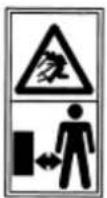
Keep a distance to persons in your vicinity.
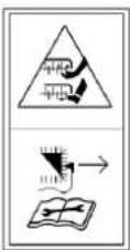
Be careful not to cut your fingers or toes.
Remove the spark plug lead before performing repair or maintenance work on the machine.
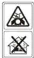
Caution! Toxic fumes!
Caution! The device must not be used in a closed or poorly ventilated environment. There is a danger of inhaling poisonous gases!
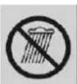
Avoid rain or humidity.

Always pay attention to eyes and hearing protection.

CE Marking
The product complies with the requirements and regulations of the European Community.
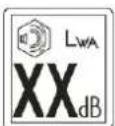
Noise level indicator
The tool noise level does not exceed 105dB.
SAFETY WARNING SYMBOL: Indicates precautions or safety information. It can also be used in conjunction with other symbols or images.
25. GENERAL SAFETY PRECAUTIONS

Before using this machine, you must read the instructions in this manual.

Observe the following safety instructions when using this device to avoid the risk of personal injury or damage to property. Please also observe the specific safety instructions in the respective chapters. In case of doubt, follow the legal guidelines or regulations for accident prevention when using the device.

CAUTION! When using machines powered by gasoline, necessary precautions should always be observed to avoid the risk of severe personal injury and damage to the device.

CAUTION! This machine generates an electromagnetic field during operation. This field may interfere with active or passive medical implants. To reduce the risk of severe or fatal injury, we recommend that persons with medical implants inform their doctor and the manufacturer of medical implants before operating this machine.
TRAINING:

Users must receive proper training in the operation, adjustment, and commissioning of the machine, including unauthorized operations.
- Read the instructions carefully. Familiarize yourself with the operating elements and proper operation of the machine. Before each use, take a moment to familiarize yourself with your device.
- Never let children or persons, who are not familiar with this manual, use the machine. Local regulations may limit the age of the operator.
- This machine is not intended for use by persons (including children) with reduced physical, sensory or mental abilities or lack of experience and knowledge unless they have been supervised or instructed by a person responsible for their safety.
- Never work when persons, especially children or pets, are nearby.
- Note that the operator or user is responsible for accidents or dangers caused by other persons or their property.
26. SAFETY INSTRUCTIONS FOR USING THE VERTICAL MOWING MACHINE
- Do not run the engine in enclosed spaces as hazardous carbon monoxide may accumulate.
- Carry out soil cultivation in daylight or under good artificial lighting. If possible, do not use the tiller on wet grass.
- Ensure good stability on slopes.
- Move the machine on foot.
- For machines on wheels, it is necessary to dig up the ground along the slope, never moving up and down the hill.
- Be especially careful when changing the direction of travel on a slope.
- Do not carry out soil cultivation on steep slopes.
- Be especially careful when turning the tiller or pulling it towards you.
- Stop the tiller blades when the machine is to be tilted so that it can be transported to other areas.
- Never use the tiller with a defective guard or guard grille without an attached device that is mounted as a buffer or moss/grass collection basket.
- Do not change the set engine control. Do not change it under any circumstances.
- Start the engine carefully. Keep a sufficient distance between your feet and the tiller.
- Start the engine. The tiller must not be tilted, even if it is to be lifted during the process. Only tilt as far as necessary and only lift it from the rear (user side).
- Never reach with hands or feet behind or under the rotating elements. Always keep a distance from the
ejection area.
- Never lift the tiller and never carry it with the engine running.
- Switch off the engine and pull out the spark plug connector before removing blockages blocking the ejection area:
- Before releasing the blockages or removing blockages in the ejection area.
- Before removing the collection bag or before checking, cleaning, or working on the milling machine.
- After hitting an obstacle, before recommissioning and starting work, check for damage to the milling machine and carry out any necessary repairs. If the milling machine starts to vibrate unusually, it should be checked immediately.
- Switch off the engine:
- If you move away from the milling machine.
- Before refueling.
-
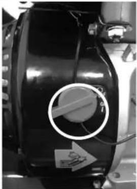
- When turning off the engine, the ignition switch must be in the OFF position (position OFF or O). The fuel tap position must be changed to OFF or O.
27. WORKING RANGE
- Keep the work area clean and well exposed. Cluttered and dark areas cause accidents.
- Check the environment in which the machine is used and remove all objects such as stones, toys, sticks, and wires that could be caught and thrown away. This can cause damage to the machine or injury to the user.
- Do not operate this machine in areas with a potentially explosive atmosphere, e.g., in the presence of flammable liquids, gases, or dust. The device generates sparks, which can ignite the dust or vapors.
- Keep away children and people present during the operation of the machine. Distractions can cause you to lose control.
28. INDIVIDUAL SAFETY
- This machine is not intended for use by persons (including children) with reduced physical, sensory or mental capabilities or lack of experience and knowledge unless they are supervised or instructed in the use of the machine by a person responsible for their safety.
• Children should be supervised to ensure that they do not play with the machine. - Stay alert, watch what you do, and use common sense when operating this device.
- Do not use this device if you are tired, ill, or under the influence of drugs, alcohol, or medication. A moment of inattention while operating this device can cause you to lose control and cause serious injury.
- Do not overexert yourself. Always make sure you have a good grip and balance. This allows better control of the tool in unexpected situations.
- Remove all adjusting keys or wrenches before turning on the machine. A wrench or wrench attached to a rotating part of the device can cause injury.
- Use safety equipment. Always wear eye protection. Safety equipment such as a dust mask, non-slip safety shoes, a hard hat, or hearing protection reduces the likelihood of personal injury.
- Dress appropriately. Do not wear loose clothing or jewelry. Keep hair, clothing, and gloves away from moving parts. Loose clothing, jewelry, or long hair can get caught in moving parts.
- If the device is used for a more extended period, vibrations can cause blood circulation problems in the hands. These effects can be increased by low ambient temperatures and by gripping the handles too tightly. The service life can be extended by wearing suitable gloves or taking regular breaks from work. Take frequent work breaks. Limit daily exposure.
29. USE AND CARE OF GASOLINE-POWERED TOOLS

CAUTION! Gasoline is highly flammable and explosive.
- Store the fuel in specially designed containers intended for this purpose.
- Fill up only outdoors, and do not smoke.
- Fill the fuel before starting the engine. Never remove the cap of the tank or add gasoline while the engine is running or when the engine is hot.
- Do not attempt to start the engine if gasoline is spilled, but move the machine away from the spillage area and avoid creating a source of ignition until the gasoline vapors have dissipated. Afterward, reattach all tank and container covers securely.
- Do not operate the engine in a closed room, as dangerous carbon monoxide may accumulate.
- The gasoline-powered device must not be used forcibly. Use the appropriate tool when refueling. A suitable tool will do the job better and safer without long trial and error.
- Never use the gasoline-powered device if the main switch is not working. Any machine that cannot be operated by a switch is dangerous and must be repaired.
- Switch off the device entirely before making adjustments, exchanging accessories, or storing tank tools. Such preventive safety measures will reduce the risk of accidentally starting the device that runs on gasoline.
- Keep unused machines out of the reach of children and do not leave this machine to persons who are not familiar with gasoline-powered devices themselves or with this manual. Petrol tools are dangerous in the hands of inexperienced operators.
- The maintenance of petrol tools. Check the alignment for parts of the device that have undergone makeshift repairs, are broken, and for all other factors that could affect the function of the gasoline tool. Have the gasoline tool repaired before use if damaged. Many accidents are caused by poorly maintained, gasoline-powered tools.
- Use the gasoline-powered device, accessories, and tools, etc., following this manual and in the manner intended for the type of gasoline-powered device, taking into account the working conditions and the work to be performed. Using the gasoline-powered tool for unintended work may cause a dangerous situation.
PERSONAL PROTECTION

Be prepared! Have at least one of the following things at hand:
- a suitable fire extinguisher (dry powder)
- a fully equipped first-aid kit, easily accessible to the machine operator and accompanying person. It should contain good dressings for lacerations/ cuts.
- a cell phone or other device to quickly call for emergency service.

Do not work alone. There must be another person nearby who is familiar with the basics of first aid.

The accompanying person must maintain a safe distance from your workplace, but must also be able to use you all the time! Work only in places where you can quickly call the emergency services!
• In the event of an injury, always follow the basic principles of first aid.
- If someone has cut themselves, cover the wound with a clean cloth and press it firmly onto the wound to stop the blood flow.
- Do not allow gasoline or oil to come into contact with the skin. Keep gasoline and oil away from the eyes. If gasoline or oil comes in contact with the eyes, wash them immediately with clean water. If the irritation is still present, consult a doctor immediately.
- Persons with poor blood circulation, who are exposed to extreme vibrations, may suffer from injuries to blood vessels or the nervous system. Vibration may cause the following symptoms in the fingers, hands, or wrists: "falling asleep" (numbness), tingling, pain, irritation, prickly sensation, change in skin color or
skin. If any of these symptoms occur, also consult a doctor immediately.
Safety has priority in case of fire:
- If a fire comes from the engine or smoke escapes from a location other than the exhaust system, first move away from the device to ensure your physical safety.
- Use a dry powder fire extinguisher to prevent the fire from spreading.
- A panic reaction could cause the fire and other damage to take on an even greater scale.
30. MAINTENANCE AND STORAGE
- Make sure that all nuts, bolts, and screws are tightened and that the device is in a safe operating condition.
- Check the catcher regularly for signs of wear and tear and functional impairments.
- Remember that on devices with gearwheels, the movement of one gearwheel can cause the other gearwheels to start rotating with it.
- When adjusting the device, be careful not to get your fingers caught between moving teeth and rigid parts of the device.
- When performing maintenance on the teeth, be aware that the teeth can still move even when the engine is switched off.
- For your safety, worn or damaged parts should be replaced immediately. Use only original spare parts and original accessories.
- Store the device in a place out of reach of children.
- Never store the machine with gasoline in the tank inside a building where vapors can cause a naked flame or spark.
- Let the engine cool down before storing it in any enclosure.
- To reduce the risk of fire, keep the engine, silencer, battery compartment, and fuel storage compartment free of grass, straw, moss, leaves, or excess grease.
- If it is necessary to empty the fuel tank, do so outdoors. The emptied fuel should be stored in a container specially designed for fuel storage or disposed of properly.
31. OVERVIEW
Fig.1

text_image
1 2 3 4 5 6 7 8 9 10 11 12 FUXTEC| 1. Handle | 7. Front carrying handle |
| 2. working height adjustment lever | 8. Oil dipstick and filler hole for engine oil |
| 3. Starter cable handle | 9. On / Off switch |
| 4. Grass catcher | 10. Fuel tank cap |
| 5. Wheels | 11. Wing screw |
| 6. Depth regulator working height adjustment | 12.Break lever |
32. ASSEMBLY
CLIP HANDLE
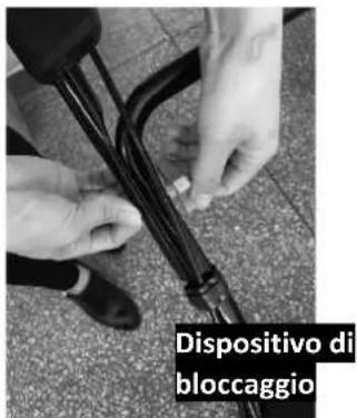
- Fasten the lower handlebar in the body of the machine using bolts, washers, and locking attachments. (Fig.2A/ Fig.2B/ Fig.2C)
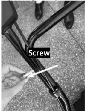
- Connect the lower handlebar and the upper handlebar with screws, washers, and locking attachments. (Fig.2D/ Fig.2E/ Fig.2F)
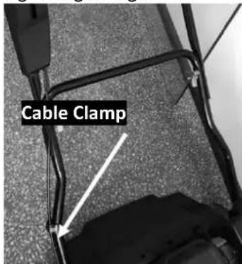
- Attach the cable clamps at the marked position and then fasten the cable. (Fig.2G)
text_image
Screw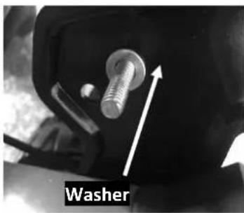
natural_image
Close-up of a mechanical component with a bolts and an upward arrow labeled 'Washer' (no other text or symbols visible)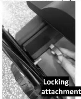
text_image
Locking attachmentFig.2A Fig.2B Fig.2C
text_image
Screw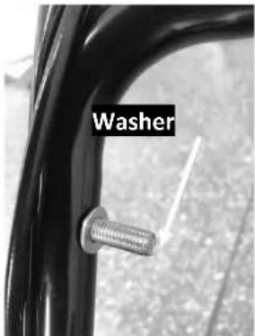
text_image
Washer
text_image
Closure- attachmentFig.2D Fig.2E Fig.2F
text_image
Cable ClampFig.2G
Manual\_FX-BV240\_Int24\_rev02
SETTING THE APPROPRIATE ANGLE
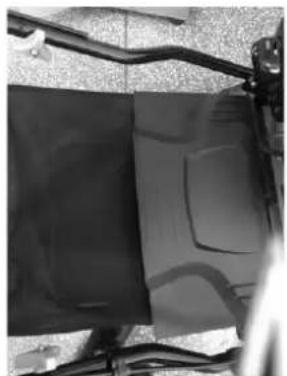
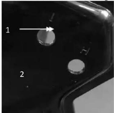
• Unscrew the locking attachments with which the lower handle was fixed. (Fig.3A)
- Move the lower handle up or down and adjust it to the desired height. With this scarifier, 2 setting heights can be selected; at 2 height levels, the lower handle is highest to the ground, and at one height, it is lowest.
- Set the correct height and then attach the lower handle with the locking attachments.

CAUTION: The left and right sides of the lower handle must be adjusted to the same height.
natural_image
Close-up of two circular metallic components labeled 1 and 2, with no visible text or symbols beyond labelsFig.3A
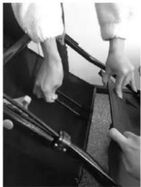
MOUNTING AND DISMOUNTING THE GRASS COLLECTOR
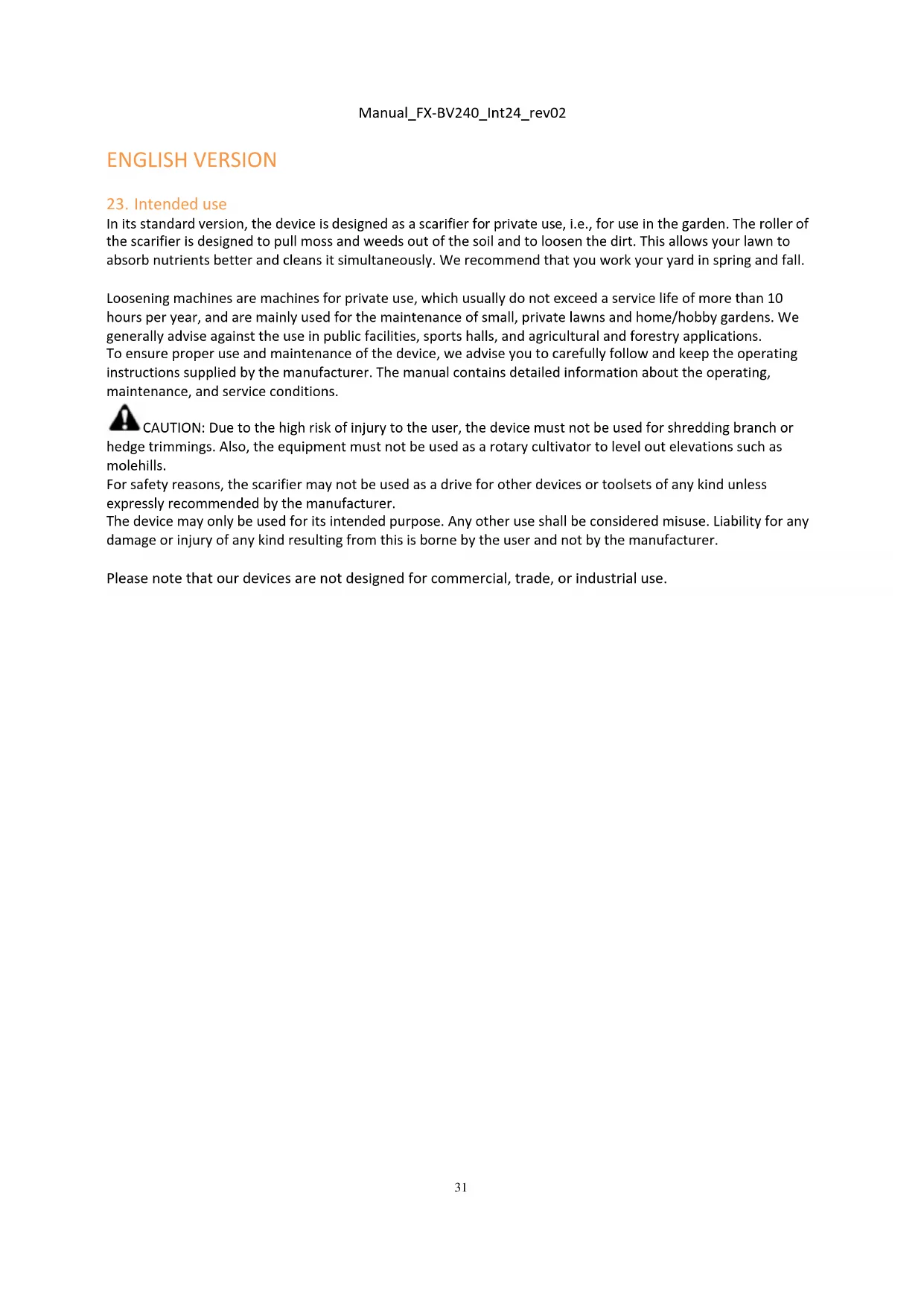
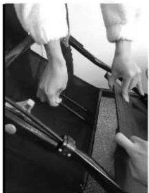
To attach: Lift the rear cover and hang the grass collector on the rear of the scarifier. (Fig.4A/Fig.4B/Fig.4C). To remove: Grip and lift the rear cover, remove grass collector.

CAUTION: Before connecting the grass collector to the device, make sure that the engine is switched off, and the mowing unit is not rotating.

natural_image
Close-up of a hand holding a pen and a black rectangular object, possibly a device or tool, with no visible text or symbols.
natural_image
Close-up of hands operating a table with a pen and a small object, no visible text or symbols
natural_image
Two black rectangular panels with abstract curved lines, mounted on a metal frame (no text or symbols visible)Fig. 4A Fig. 4B Fig. 4C
STARTER
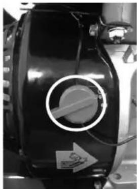
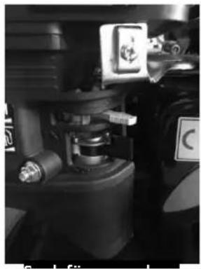
Move the throttle lever from the engine to the cable guide. (Fig.5)

natural_image
Person cleaning a car interior with visible wiring and a black plastic box (no text or symbols)Fig.5
CUTTING DEPTH
Move the lever outward to release it from the rack. Move the lever forward or backward to adjust the height. (Fig.6 and see 6.4).

natural_image
Close-up of a hand operating a black circular component on a metallic tray (no visible text or symbols)Fig. 6
33. USER MANUAL
Maintain the engine as described in the separate engine manual for your scarifier, with gasoline and oil. Read the instructions carefully.

CAUTION! Gasoline is highly flammable.
Store the fuel in containers specially designed for this purpose.
Only refuel outdoors and before starting the engine. Do not smoke while refueling or working with the fuel.
Never remove the fuel tank cap or add gasoline while the engine is running or when the engine is hot.
Do not start the engine if gasoline is spilled. In this case, the machine must be moved away from the spillage area, and no source of ignition must be created until the petrol vapors have evaporated.
Securely fasten all fuel tanks and container lids in their original place.
Before tilting the scarifier to service the blades or drain oil, there must be no fuel left in the tank.

CAUTION: Never refill the fuel tank in enclosed spaces, while the engine is running or before the engine
has cooled down for at least 15 minutes after start-up.
Manual\_FX-BV240\_Int24\_rev02
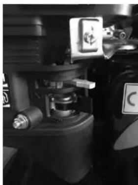
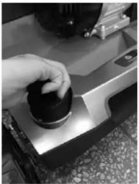
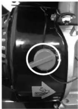
TO START THE ENGINE
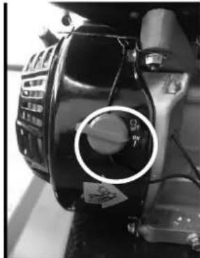
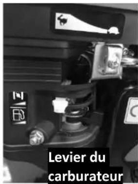
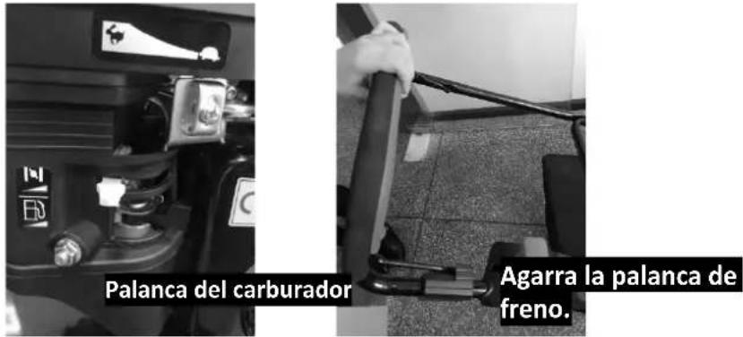
- Before you start the engine, please turn the engine switch to "ON." (Fig.7A)
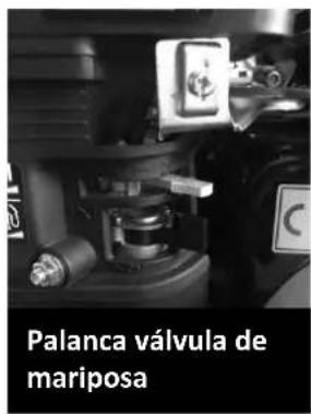
- To start a cold engine, set the throttle stick to "On" (Fig. 7B). Move the throttle lever to the "Off" position. (Fig.7B).
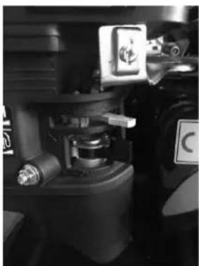
- Stand behind the device, grasp the brake lever, and hold it against the lower handle.
• (Fig.7C) - Hold the brake lever as shown in Fig.7C and quickly pull up the starter handle, as shown in Fig.7D. After starting the engine, slowly return it to the cable guide pins.
- Set the throttle lever to the "On" position. (Fig.7F)

NOTE! If the cutting unit comes into contact with the ground, the device may move jerkily.
natural_image
Close-up of a mechanical component with a circular hole and label, no visible text or symbols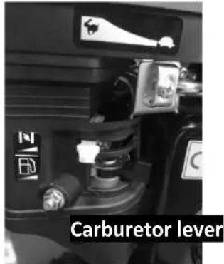
text_image
Carburetor lever
text_image
Grasp the brake lever.Fig.7A Fig.7B Fig.7C

natural_image
Person holding a device next to a black box, possibly a vehicle or container (no visible text or symbols)Throttle lever
natural_image
Close-up of mechanical components with no visible text or symbolsFig.7D Fig.7E
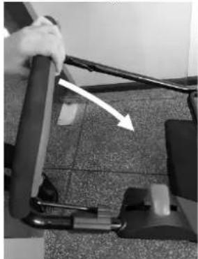
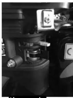
TO STOP THE ENGINE

CAUTION: After the engine is turned off, the blade continues to rotate for several seconds.
- Release the brake lever to stop the engine and blade. (Fig. 8A)
- Set the engine switch to the "OFF" position. (Fig.8B)
natural_image
Close-up of a hand gripping a mechanical component with a white arrow pointing to a section (no visible text or symbols)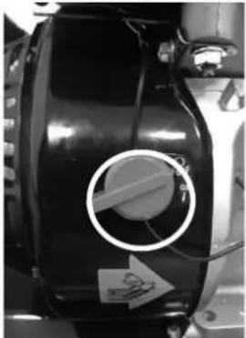
natural_image
Close-up of a black industrial component with a circular mark and directional arrow, no visible text or symbols.Fig.8A Fig.8B
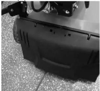
GRASS COLLECTOR
Working without grass collector (optional)
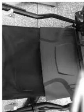
With the scarifier, you can work with or without a grass collector. Whenever you remove the grass collector, the protective flap falls. When mowing the lawn without an attached grass collector, the cut grass is thrown directly onto the ground. (Abb.9A)
Working with the grass collector When working with the grass collector, the cuttings are disposed of via the grass collector. When the grass collector bag is full of clippings, you must empty the grass collector bag and clean it.
- Switch off the engine and wait until it stops.
- Raise the protective flap and release the grass collector bag. (Fig.9B)
• Empty the contents.
natural_image
Close-up of a black plastic enclosure with visible internal components and mounting brackets (no text or symbols)
natural_image
Close-up of hands holding a tool with scissors and weights, no visible text or symbolsFig.9A Fig.9B
INSTRUCTIONS FOR HEIGHT ADJUSTMENT

CAUTION: Never adjust the scarifier at any time without first switching off the engine.
Your scarifier is equipped with a lever for height adjustment, which offers an unlimited number of working positions. The working positions are dimensioned in -3mm, -6mm, -9mm, -12mm, and -15mm height.
- Stop the scarifier and disconnect the spark plug cable before changing the cutting height of the device.
- To change the cutting height, turn the front knob clockwise or vice versa to the desired height.
- Move the transport lever to transport position to prevent the mowing deck from touching the ground when the work is finished.
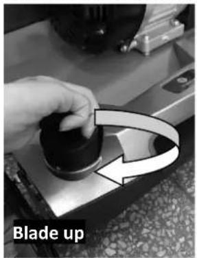
text_image
Blade up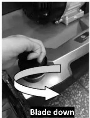
text_image
Blade downFig.10A Fig.10B
34. REPLACING THE ROLLER

CAUTION: Make sure to wear work gloves.

Caution: Only use original scarifier/aerator shafts approved by the manufacturer.
The device can be mounted with the scarifier roller or the aerator roller.
Only replace the roller with an original roller as this ensures optimum performance and safety under all conditions.
To change the scarifier roller or the optionally available aerator roller, proceed as follows
- Switch off the engine and let it cool down.
- Remove the spark plug connector.
- Remove the grass collector.
Lift the device slightly at the front.

Note: Do not lift the machine too high. Otherwise, fuel may leak from the tank. Drain fuel if necessary before changing the roller.
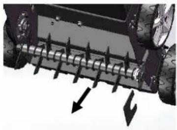
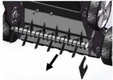
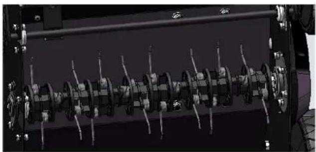
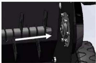
Remove the roller.
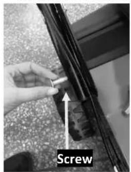
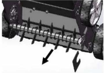
- Remove the four screws. (Fig.11B)
- Lift the roller and pull it out in the direction of the arrows. (Fig.11C)
natural_image
Technical illustration of a robotic car with visible wheels and mechanical components, showing motion direction (no text or symbols)Fig.11A Fig.11B
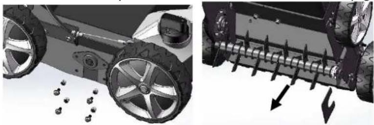
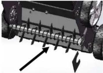
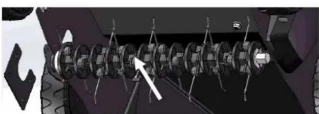
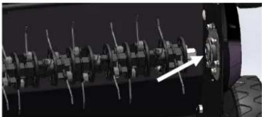
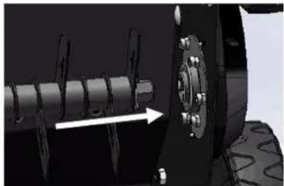
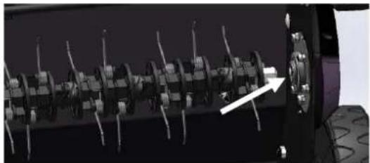
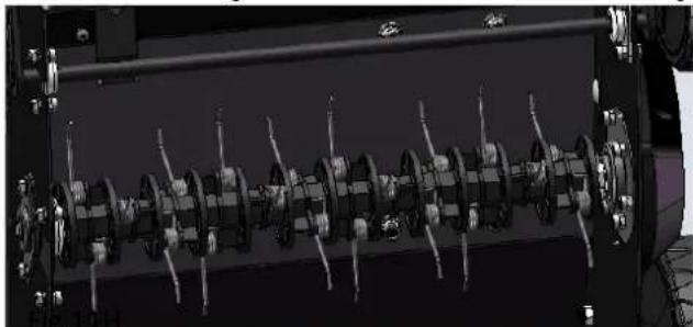
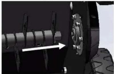
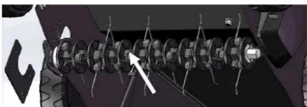
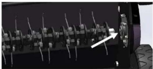
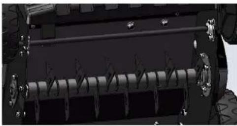
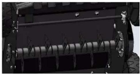
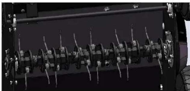
Attach the roller.
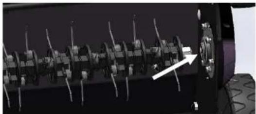
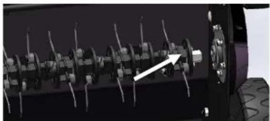
- Push the new roller in the direction of the arrows, insert the shaft into the hexagon socket and press the other side into the holder. (Fig.11C/ Fig.11D/ Fig.11E).
- Fasten the roller again with the two screws.
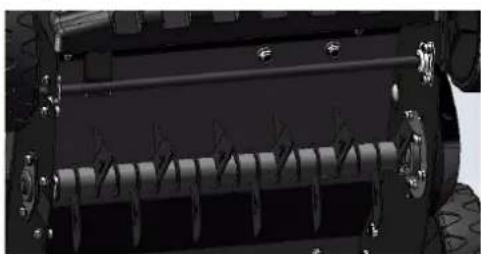
- Check if the roller is seated correctly.
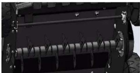
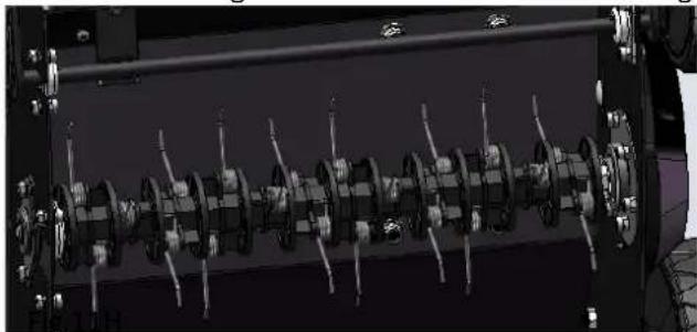
- Fix the aerator roller and the scarifier roller. (Fig.11F/ Fig.11G/ Fig.11H).
natural_image
Close-up of a mechanical component with threaded fasteners and directional arrows indicating force or movement (no text or symbols)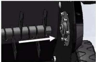
natural_image
Mechanical assembly diagram showing a shaft and wheel assembly with an arrow indicating direction (no text or symbols present)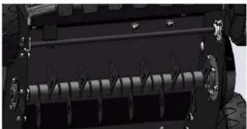
natural_image
Close-up of a vehicle's internal mechanical components, possibly a conveyor or roller, with no visible text or symbols.Fig.11C Fig.11D Fig.11E
natural_image
Mechanical assembly diagram showing a chain of gears or cylinders with a white arrow pointing to one (no text or symbols present)Fig.11F Fig.11G
natural_image
Close-up of a mechanical assembly with multiple gears and a central knob, no visible text or symbols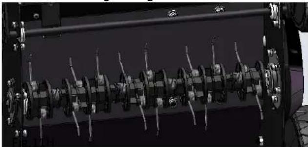
natural_image
Mechanical assembly diagram showing a multi-stage mechanical component with rotating parts and connecting rods (no visible text or labels)35. FUNCTIONAL DESCRIPTION
The scarifier is pushed by hand over the grass area to be dug. A petrol engine drives the cutting tools. The cutting depth is set by adjusting the individual central height adjustment mechanism.
Loosening up:
Through its rotation, the cutting unit removes the felt layer formed by moss, lichen, and weeds. It transports the loosened material to the outside or into the grass collector. During cutting, the blades penetrate the soil and ensure that the lawn is loosened, and the nutrients can be better absorbed. We recommend loosening the yard in spring (April/May) and autumn (October).
Aerate:
The cutting mechanism (the aeration roller) rotates, combs the lawn, and aerates the slightly mossy areas. The removed moss is transported to the outside or into the grass collector. During aeration, the soil surface is rubbed down, which improves drainage and, at the same time, facilitates the absorption of oxygen.
We recommend aerating the lawn as needed throughout the vegetation period.
36. MAINTENANCE INSTRUCTIONS
IGNITION PLUG
Only use original spark plugs for replacement. For best results, replace the spark plug every 100 operating hours.
BRAKE PADS
Check and replace the engine brake pads regularly at the customer service. Only original parts can be used for replacement.
USE OF GREASE

CAUTION: PULL OUT THE SPARK PLUG BEFORE MAINTENANCE.
- WHEELS - Lubricate the ball bearings with a light lubricant at least once per season.
- ENGINE - Follow the engine manual for lubrication information.
37. CLEANING

CAUTION: Do not spray the engine with a hose. There is a risk of water damaging the engine or aminating the fuel system.
- Wipe the canopy with a dry cloth.
- Clean the deck by tilting the scarifier so that the spark plug points upwards.
ENGINE AIR FILTER

CAUTION: Do not allow dirt or dust to clog the foam element of the air filter.
The engine air cleaner element must be serviced (cleaned) after 25 hours of regular use. If the machine is used in dry, dusty conditions, the foam element must be checked regularly.
CLEANING THE AIR FILTER
- Remove the cover. (Fig.12A)
- Blow away the dust of the filter element. (Fig.12B).
- Apply a few drops of SAE30 oil to the foam filter and then press firmly together to remove excess oil.
- Reinstall the filter.
- Close the filter cover.

NOTE: Replace the filter if it is frayed, torn, damaged, or if it seems impossible to clean it.

text_image
Filter cover Tab Filter elementFig.12A Fig.12B
ENGINE
The maintenance instructions for the engine can be found in the separate engine manual.
Store the engine oil according to the instructions in the separate engine manual that comes with your device.
Read and follow the instructions carefully.
Maintain the air filter according to the separate engine manual under normal conditions. Under extremely dusty conditions, the air filter must be cleaned every few hours. Poor engine performance and clogging usually indicate that the air filter should be serviced.
Refer to the separate engine manual that came with your device for information on how to service the air filter.
The spark plug should be cleaned once per season, and the air filter slide-in should be reset. Spark plug replacement is recommended at the beginning of each season; check the engine manual for the correct plug type.
Clean the engine regularly with a cloth or brush. Keep the cooling system (area of the housing fan) clean to allow proper air circulation, which is essential for engine performance and life. Be sure to remove all grass, dirt, and combustible deposits from the muffler area.
38. STORAGE AND TRANSPORTATION
Storage
The following steps should be taken to prepare the mower for storage.
- Empty the tank.
• Empty the fuel tank with a suction pump. - CAUTION! Do not drain the gasoline in closed rooms and the immediate vicinity of open fire etc. Do not smoke under any circumstances! Gasoline vapors can cause explosions or fires.
- Start the engine and let it run until it has used up all remaining fuel reserves and deposits.
- Remove the spark plug. Use an oil can to fill approx. 20 ml of oil into the combustion chamber. Operate the starter to distribute the oil evenly over the combustion chamber. Reinsert the spark plug.
- Clean and grease the scarifier carefully, as described in the upper chapter "Use of Grease."
- Lightly grease the blades to prevent corrosion.
- Store the scarifier out of reach of unauthorized persons and in a dry, clean, and frost-free place.
CAUTION! The engine must be completely cooled down before storing the lawnmower.
NOTE: When storing any type of power equipment in an unventilated or material storage facility,
- it must be ensured that the device is stainless. Coat the device, especially cables and all moving parts, with light oil or silicone.
- Make sure that you do not bend or kink any cables.
- if the starter cable comes loose from the cable guide on the handle, disconnect and ground the spark plug
wire, press the blade control lever, and then slowly pull the starter cable out of the engine. Slide the starter cable into the cable guide pins on the handle.
Transportation
- Move the transport lever into the transport position.
- Switching off the engine

Danger!
Before transport, always switch off the engine and let it cool down and remove the spark plug connector. The device must not be tilted during transport. When transporting the scarifier in or on a vehicle, make sure that it does not move unintentionally.
Empty the fuel tank before transporting the device. The fuel tank cap must be firmly closed.
- TROUBLESHOOTING AND REPAIR
| Problem | Possible reasons | Corrective actions |
| The engine does not start | The throttle valve is not in the correct position. | Move the throttle valve to the correct position. |
| The fuel tank is empty. | Fill the tank with fuel: see MANUAL. | |
| The air filter element is dirty. | Clean the air filter element: see MANUAL. | |
| The spark plug is loose. | Tighten the spark plug. | |
| The spark plug lead is loose or disconnected from the plug. | Fit the spark plug cable to the spark plug. | |
| The gap does not correspond to the spark plug. | Adjust the correct gap between the electrodes. | |
| The spark plug is defective. | Fit new, correctly closed plug: see MANUAL. | |
| The carburetor is running full of fuel. | Remove the air filter element and pull continuously on the starter cable until the carburetor has freed itself and then install the air filter element. | |
| Defective ignition module. | Contact customer service. | |
| Engine speed is reduced. | The cutting depth is too large | Set to the smaller cutting depth |
| The grass too high | Mow the lawn before loosening. | |
| The discharge opening is blocked | Pull out the spark plug connector and remove the blockage. | |
| The air filter is clogged | Clean air filter: see MANUAL. | |
| Poor results when mowing | The cutting depth is too small | Adjust to more considerable cutting depth. |
| Worn cutting blades | Exchange of the cutting blades in a special workshop. | |
| The grass collector never fills up. | The grass collector is full/clogged. | Stop the scarifier. Empty or clean the grass collector |
| The ejection chute is blocked | Pull out spark plug connector, clean ejector shaft | |
| Unusual noises | Screws, nuts, or other fastening parts are loose. | Tighten the parts. |
| Vibration | The cutting device is loose. | Tighten the blade firmly. |
| The cutting device is not in balance. | Balance the blade. |
40. ENVIRONMENT
If your machine needs to be replaced after a long period of use, do not dispose of it in the household waste, but in an environmentally friendly manner.
- TECHNICAL DATA
| Model Name | FX-BV240 |
| Drive system | Manual operation |
| Engine data (cc/kw/rpm) | 212cc 4.1kw/3400rpm |
| Gasoline tank volume (l) | 3.6 |
| Oil volume (l) | 0.6 |
| Material | Steel |
| Working width (mm) | 400mm |
| Blade + Claws | 18 blades, 24 claws |
| Working depth (mm) | minus 15 to plus 5 mm (below and above ground) |
| Wheel size (inch)(front/rear) | 8 inch (front)/8 inch (back) |
| Front carry handle | yes |
| Grass collector basket capacity | 45L |
42. EC DECLARATION OF CONFORMITY
Manufacturer / Producer
FUXTEC GmbH
Kappstraße 69, 71083 Herrenberg Germany / Germany
Email: info@fuxtec.co.uk Web: www.fuxtec.co.uk
Designation/name Petrol Scarifier FX-BV240
EC Directive / EC directive 2006 42 EC 2014/30/EU
Applicable standards
EN ISO 14982:2009
EN 13684:2018
We declare that the device mentioned above meets the above-stated EC directives' essential safety and health requirements.
Any manipulation or change of the device not being explicitly authorised by us in advance renders this document null and void.
Custody of technical documents: FUXTEC GmbH ● Kappstraße 69 ● 71083 Herrenberg ● Germany, L. Zirkler, Management Board
Herrenberg, November the 7 ^th , 2023
C. Bille
Storage of the technical documentation:
FUXTEC GmbH ● Kappstraße 69 ● 71083 Herrenberg ● Germany L. Zirkler, CEO
VERSION FRANCAISE
natural_image
Close-up of a dark, reflective surface with two circular indentations and directional arrows (no text or symbols)Fig.3A
MONTAGE ET DEMONTAGE DU SAC DE RAMASSAGE D'HERBE
natural_image
Close-up of a hand holding a black electronic device with wires and a small component, no visible text or symbols.Fig. 4A

natural_image
Close-up of hands operating a mechanical device with tools (no visible text or symbols)Fig. 4B
natural_image
Two-panel black-and-white photo showing a dark rectangular object on the left and a faint abstract line drawing on the right, with no visible text or symbols.Fig. 4C
DÉMARREUR
natural_image
Person holding a small object next to a black box, no visible text or symbolsFig.5
PROFONDEUR DE COUPE
natural_image
Close-up of a hand operating a black knob on a metallic mechanical device (no visible text or symbols)Fig. 6
54. INSTRUCTIONS D'UTILISATION
natural_image
Close-up of a mechanical component with a circular hole and a small label, no visible text or symbols.Fig.7A
Fig.7B
Fig.7C
natural_image
Person installing or adjusting a black plastic bag on a car (no visible text or symbols)Fig.7D
Levier de gaz
Fig.7E
natural_image
Close-up of a mechanical assembly with no visible text or symbolsPOUR ARRÊTER LE MOTEUR

natural_image
Close-up of a hand holding a black mechanical component with an arrow pointing to a textured surface (no visible text or symbols)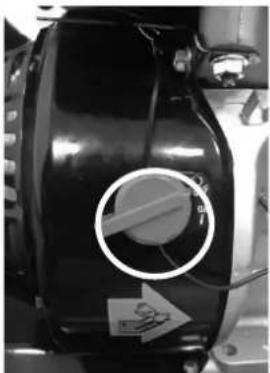
natural_image
Close-up of a black industrial component with a circular hole and directional arrow, no visible text or symbols.Fig.8A Fig.8B
BAC DE RAMASSAGE D'HERBE
natural_image
Close-up of a black plastic enclosure with visible internal components and mounting brackets (no text or symbols)Fig.9A
Fig.9B

natural_image
Close-up of hands manipulating a black object with wires, possibly a gun or mechanical component (no visible text or symbols)INSTRUCTIONS POUR LE RÉGLAGE DE LA HAUTEUR

natural_image
Close-up of a car's front wheel assembly with visible tires and wheels, no text or symbols presentFig.11A
natural_image
Close-up of a mechanical component with directional arrows indicating force or movement (no text or symbols visible)Fig.11B
natural_image
Close-up of a vehicle's wheel rim with directional arrows indicating force or movement (no text or symbols)Fig.11C
natural_image
Mechanical assembly diagram showing a shaft and wheel assembly with an arrow indicating direction (no text or symbols present)Fig.11E
natural_image
Close-up of a military vehicle's internal gear system with no visible text or symbols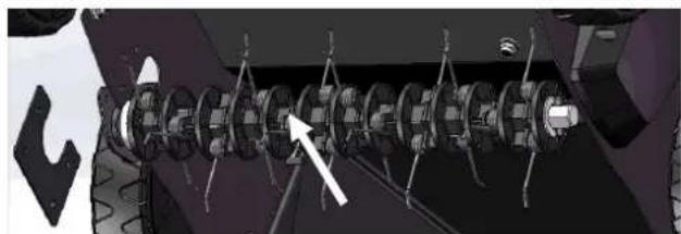
natural_image
3D rendering of a mechanical assembly with gears and rods, no visible text or symbolsFig.11F
natural_image
Close-up of a mechanical component with multiple teeth and a central knob, showing no visible text or symbols.Fig.11G
natural_image
Mechanical assembly diagram showing a multi-cranked gear mechanism with no visible text or symbols56. DESCRIPTION FONCTIONNELLE
natural_image
Simple line drawing of a lawn mower (no text or symbols)
ÉLÉMENTS D'EMBALLAGE À SÉPARER ET À DÉPOSER DANS LE BAC DE TRI

- DONNÉES TECHNIQUES
62. DÉCLARATION DE CONFORMITÉ CE
Fabricant / Producer
FUXTEC GmbH
Kappstraße 69, 71083 Herrenberg Allemagne / Germany
Email: info@fuxtec.fr Web: www.fuxtec.fr
Directives CE / EC directive 2006 42 EC
2014/30/EU
Normes appliquées / applicable standards
EN ISO 14982:2009
EN 13684:2018
Hereby we declare that the above mentioned machine meet the essential safety and health requirements of the above stated EC directives. Any manipulation or change of the machine not being explicitly authorized by us in advance renders this document null and void.
Conservation des documents techniques : FUXTEC GmbH ● Kappstraße 69 ● 71083
Herrenberg ● Germany, L. Zirkler, Direction
Herrenberg, 07.11.2023
C. Bille
natural_image
Close-up of a car window with a screw and nut, labeled 'Rondella' (no other text or symbols visible)Fig. 2F
natural_image
Close-up of two circular objects with arrows pointing to them, labeled 1 and 2 (no text or symbols beyond labels)Fig.3A
MONTAGGIO E SMONTAGGIO DEL CESTO DI RACCOLTA
natural_image
Close-up of a black electronic device with wires and a tool, no visible text or symbolsFig. 4A

natural_image
Close-up of hands holding a small object on a dark surface, possibly a gun or gun piece, with no visible text or symbols.Fig. 4B
natural_image
Two black panels showing abstract curved patterns on a textured surface, with no visible text or symbols.Fig. 4C
DISPOSITIVO D'AVVIAMENTO
natural_image
Person holding a device next to a black box, no visible text or symbolsFig.5
PROFONDITÀ DI TAGLIO
natural_image
Close-up of a hand operating a black cylindrical device on a metallic base (no visible text or symbols)Fig. 6
72. ISTRUZIONI D'USO
natural_image
Close-up of a mechanical component with a circular dial indicator and label (no readable text or symbols)Fig.7A
Fig.7B
Fig. 7C
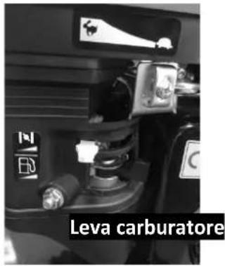
text_image
Leva carburatore
text_image
Afferrare la leva del freno.
natural_image
Person holding a device with cables, next to a black box (no visible text or symbols)Fig.7D
Fig.7E
natural_image
Close-up of a mechanical assembly with no visible text or symbolsARRESTO DEL MOTORE

natural_image
Close-up of a hand using a tool to lift a textured surface, with an arrow indicating direction (no text or symbols visible)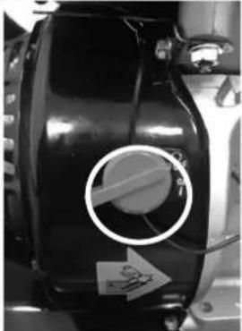
natural_image
Close-up of a black industrial component with a circular opening and a white arrow pointing to it, no visible text or symbols.Fig.8A Fig.8B
CESTO DI RACCOLTA
natural_image
Close-up of a black plastic enclosure with visible internal components and mounting brackets (no text or symbols)Fig.9A
Fig.9B

natural_image
Close-up of hands holding a tool with a string, no visible text or symbolsnatural_image
Close-up of a car's front wheel assembly with visible tire, wheels, and mounting holes (no text or symbols)Fig.11A
natural_image
Mechanical component with threaded rod and two downward arrows indicating force or motion (no text or symbols)Fig.11B
natural_image
Close-up of a mechanical component with directional arrows indicating movement or force (no text or symbols visible)Fig.11C
natural_image
Mechanical assembly diagram showing a vehicle wheel and shaft assembly with an arrow indicating direction (no text or symbols present)Fig.11E
natural_image
Close-up of a vehicle's internal mechanical component with no visible text or symbols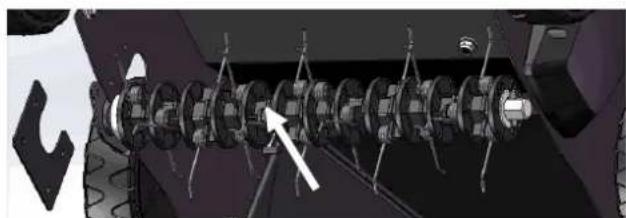
natural_image
Mechanical assembly diagram showing a shaft and housing with no visible text or symbolsFig.11F
natural_image
Close-up of a mechanical component with multiple gears and a central hub, showing no visible text or symbols.Fig.11G
natural_image
Mechanical assembly diagram showing a multi-stage motor or gear mechanism with no visible text or symbolsCANDELA DI ACCENSIONE
Email: info@fuxtec.it Web: www.fuxtec.it
Norme applicate / applicable standards
EN ISO 14982:2009
EN 13684:2018
Hereby we declare that the above mentioned machine meet the essential safety and health requirements of the above stated EC directives. Any manipulation or change of the machine not being explicitly authorized by us in advance renders this document null and void.
natural_image
Close-up of two circular components labeled 1 and 2, with arrows pointing to them (no text or symbols beyond labels)Fig.3A
MONTAJE Y DESMONTAJE DE LA CESTA DE RECOGIDA
natural_image
Close-up of a black electronic device with wires and a clip, no visible text or symbolsFig. 4A
natural_image
Close-up of hands operating a rifle with a bow, no visible text or symbolsFig. 4B

natural_image
Two black rectangular panels with curved lines, mounted on a metal frame (no visible text or symbols)Fig. 4C
natural_image
Person using a tool to adjust or install a black electronic device (no visible text or symbols)Fig.5
natural_image
Close-up of a hand operating a black knob on a metallic mechanical device (no visible text or symbols)Fig. 6
91. INSTRUCCIONES DE USO
natural_image
Close-up of a mechanical component with a circular highlight and label (no readable text or symbols)Fig.7A
Fig.7B
text_image
Palanca del carburador Agarra la palanca de freno.Fig. 7C

natural_image
Person using a carton to lift a black box, no visible text or symbolsFig.7D
Fig.7E
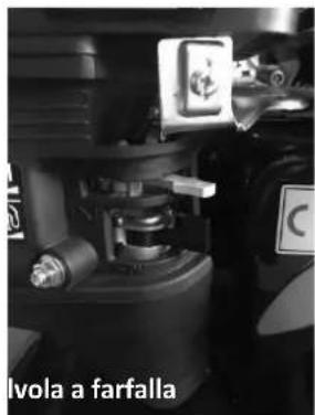
text_image
Palanca válvula de mariposaPARADA DEL MOTOR
natural_image
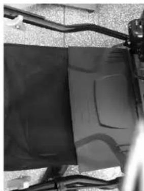
Close-up of a hand holding a chair with a white arrow pointing to the seat area (no text or symbols visible)Fig.8A Fig.8B
natural_image
Close-up of a black cylindrical device with a circular button and a white arrow, no visible text or symbols.CESTA DE RECOGIDA
natural_image
Close-up of a black plastic enclosure with visible internal components and mounting brackets (no text or symbols)Fig.9A Fig.9B

natural_image
Close-up of hands manipulating a black object with wires, possibly a tool or device (no visible text or symbols)natural_image
Close-up of a car's front wheel and suspension components with small bolts (no text or symbols visible)Fig.11A
natural_image
Close-up of a vehicle's wheel rim with visible tire tracks and two arrows indicating force or movement (no text or symbols)Fig.11B
natural_image
Close-up of a mechanical component with two arrows pointing to a textured surface (no visible text or symbols)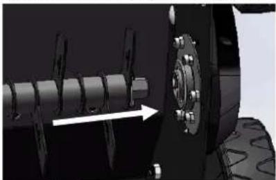
natural_image
Mechanical assembly diagram showing a vehicle wheel with attached components and a directional arrow (no text or symbols)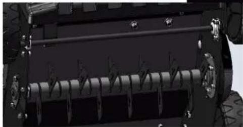
natural_image
Close-up of a vehicle's internal mechanical component with coiled spring and mounting flanges (no visible text or symbols)Fig.11C
Fig.11D
Fig.11E
natural_image
Mechanical assembly diagram showing a chain of gears or cylinders with a white arrow pointing to one end (no text or symbols present)Fig.11F
natural_image
Close-up of a mechanical assembly with multiple gears and a central hub, no visible text or symbolsFig.11G
Fig.11H
natural_image
Mechanical assembly diagram showing a multi-cranked gear mechanism with no visible text or symbolsFabricante / Producer
FUXTEC GmbH
Hereby we declare that the above mentioned machine meet the essential safety and health requirements of the above stated EC directives. Any manipulation or change of the machine not being explicitly authorized by us in advance renders this document null and void.
Fig.2A Fig.2B Fig.2C
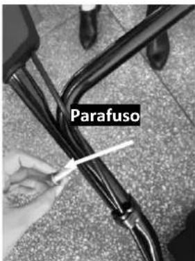
text_image
Parafuso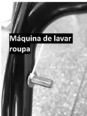
text_image
Máquina de lavar roupa
Fig.2D Fig.2E Fig.2F
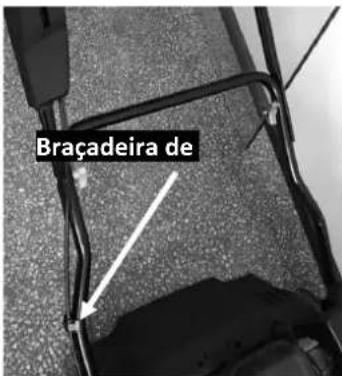
text_image
Braçadeira deFig.2G
natural_image
Close-up of two circular objects on a dark surface, labeled 1 and 2 with an arrow pointing to one (no text or symbols beyond labels)Fig.3A
MONTAGEM E DESMONTAGEM DO DISPOSITIVO DE RECOLHA DE RELVA
natural_image
Close-up of a black plastic object with a white tool partially visible, no text or symbols present.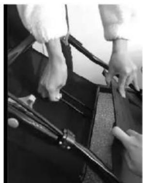
natural_image
Close-up of hands holding a rifle with visible stock, no text or symbols present
natural_image
Close-up of a dark, curved surface with faint internal patterns, possibly a material sample or abstract design (no text or symbols visible)Fig. 4A Fig. 4B Fig. 4C
INSTALADOR
natural_image
Person holding a device next to a black object, possibly a vehicle or device (no visible text or symbols)Fig.5
DICA DE CORTE
Deslocar a alavanca para fora para a soltar do suporte. Deslocar a alavanca para a frente ou para trás para regular a altura. (Fig. 6 e ver 6.4).
natural_image
Close-up of a hand operating a black circular component on a metallic workbench (no visible text or symbols)Fig. 6
natural_image
Close-up of a mechanical component with a circular dial and directional arrow, no visible text or symbols
natural_image
Side-by-side comparison of a car interior showing the front and side views of a vehicle (no visible text or symbols)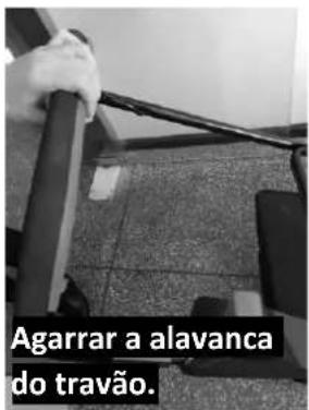
Fig.7A Fig.7B Fig.7C

natural_image
Person using a handheld device to lift a black object, no visible text or symbolsFig.7D Fig.7E
natural_image
Close-up of mechanical components with no visible text or symbolsPARA PARAR O MOTOR

natural_image
Close-up of a hand using a tool to lift a car seatbelt, with a white arrow indicating the motion direction (no text or symbols visible)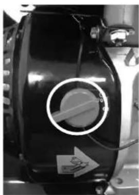
natural_image
Close-up of a black mechanical component with a circular dial and directional arrow, no visible text or symbols.Fig.8A Fig.8B
APANHADOR DE RELVA
natural_image
Close-up of a black plastic enclosure with visible internal components and mounting brackets (no text or symbols)Fig.9A Fig.9B

natural_image
Close-up of hands holding a tool on a dark surface, possibly a musical instrument or electronic device (no visible text or symbols)natural_image
Close-up of a car's front wheel and suspension components (no visible text or symbols)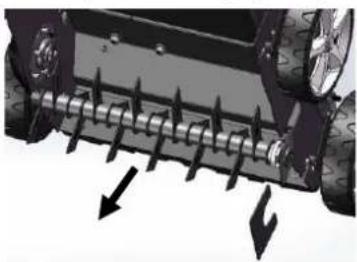
natural_image
Close-up of a vehicle's wheel rim with mechanical teeth and directional arrows indicating force or movement (no text or symbols)Fig.11A Fig.11B
Fixar o rolo.
natural_image
Close-up of a vehicle's wheel rim with directional arrows indicating force or movement (no text or symbols)Fig.11C
Fig.11D

natural_image
Mechanical assembly diagram showing a shaft and wheel with an arrow indicating direction (no text or symbols)Fig.11E

natural_image
Close-up of a mechanical roller or spring assembly with no visible text or symbols
natural_image
Mechanical assembly diagram showing a shaft and housing with no visible text or symbolsFig.11G

natural_image
Close-up of a mechanical assembly with multiple gears and a central shaft, no visible text or symbolsFig.11F

natural_image
Mechanical assembly diagram showing a multi-cranked gear mechanism with no visible text or symbolsFig.11H
natural_image
Close-up of a mechanical component with a threaded bolt and arrow, labeled 'Wasmachine' (no other text or symbols)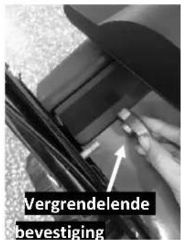
text_image
Vergrendelende bevestigingFig.2A Afb.2B Afb.2C

text_image
Schroef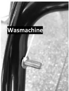
text_image
Wasmachine
text_image
Bevestiging rolluikFig.2D Afb.2E Fig.2F
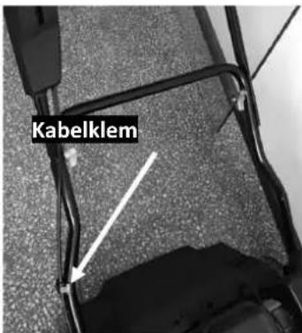
text_image
KabelklemFig.2G
DE JUISTE INSTELLENHOEK
natural_image
Microscopic view of two circular particles on a dark surface, labeled 1 and 2 with an arrow indicating direction (no text or symbols beyond labels)Fig.3A
MONTAGE EN DEMONTAGE VAN DE GRASVANGER
natural_image
Close-up of a black electronic device with wires and a small component, no visible text or symbols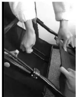
natural_image
Close-up of hands operating a mechanical device with a tool, no visible text or symbols
natural_image
Close-up of a black plastic panel with visible internal markings, mounted on a metal bracket (no text or symbols)natural_image
Person adjusting a black object with wires, possibly part of a vehicle or device (no visible text or symbols)Fig.5
KNIPTIP TIP
natural_image
Close-up of a hand pressing down on a mechanical component (no visible text or symbols)Fig. 6
natural_image
Close-up of a motorcycle's front wheel with a circular dial indicator and a small label (no readable text or symbols)natural_image
Side-by-side comparison of a car interior showing the left panel with 'EVE' logo and a right panel with a hand gesture (no readable text or symbols)
text_image
Pak de remhendel vast.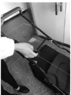
natural_image
Person handling a black device with wires, possibly a vehicle or equipment component (no visible text or symbols)Fig.7D Fig.7E

natural_image
Close-up of mechanical components with no visible text or symbolsOM DE TE STOPPENMOTOR

natural_image
Close-up of a hand holding a cable with a white arrow pointing to a component, against a textured gray background (no visible text or symbols)
natural_image
Close-up of a black industrial component with a circular dial and directional arrow (no visible text or symbols)Fig.8A Fig.8B
GRASVANGER
natural_image
Close-up of a black plastic enclosure with visible internal components and mounting brackets (no text or symbols)Fig.9A Fig.9B

natural_image
Close-up of hands holding a rifle with visible blade and bow (no text or symbols)INSTRUCTIES VOOR HOOGTEVERSTELLING

natural_image
Close-up of a car's front wheel and suspension components (no visible text or symbols)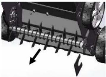
natural_image
Close-up of a vehicle's wheel rim with directional arrows indicating force or movement (no text or symbols)Fig.11A Fig.11B
Bevestig de rol.
natural_image
Close-up of a vehicle's wheel rim with directional arrows indicating force or movement (no text or symbols)Fig.11C
Fig.11D

natural_image
Mechanical assembly diagram showing a shaft and wheel with an arrow indicating direction (no text or symbols)Afb.11E
natural_image
Close-up of a vehicle's internal mechanical component with coiled spring and mounting flanges (no visible text or symbols)
natural_image
Mechanical assembly diagram showing a shaft and housing with no visible text or symbolsFig.11G
natural_image
Close-up of a mechanical assembly with multiple gears and a central shaft, no visible text or symbolsFig.11F

natural_image
Mechanical assembly diagram showing a multi-cranked gear mechanism with no visible text or symbolsFig.11H
138. FUNCTIONELE BESCHRIJVING
- PROBLEEMOPLOSSING EN CORRECTIE
L. Zirkler, Management
SVENSK VERSION
natural_image
Close-up of two circular metallic components on a dark surface, labeled 1 and 2 with an arrow pointing to one (no text or symbols beyond labels)Bild 3A
MONTERING OCH DEMONTERING AV GRÄSUPPSAMLAREN
natural_image
Close-up of a black plastic object with a small hole and metal clamped parts, no visible text or symbols.
natural_image
Close-up of hands operating a rifle with a bow, no visible text or symbols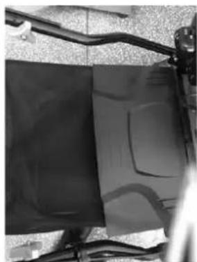
natural_image
Black-and-white photo of a mechanical device with visible wiring and a dark panel (no text or symbols)natural_image
Person cleaning a car window with a tool (no visible text or symbols)Bild 5
AVSKÄRANDE TIPP
natural_image
Close-up of a hand pressing down on a mechanical component (no visible text or symbols)Bild 6
158. BRUKSANVISNING
natural_image
Close-up of a motorcycle's side panel with a circular dial indicator and a white arrow pointing to the knob (no visible text or symbols)natural_image
Close-up of a mechanical device with a label 'E' and an arrow pointing to a component (no readable text or symbols)
text_image
Ta tag i bromshandtaget.
natural_image
Person in lab coat handling cables next to a dark object on carpet (no visible text or symbols)Bild 7D Fig. 7E
natural_image
Close-up of a mechanical assembly with no visible text or symbolsFÖR ATT STOPPA MOTORN

natural_image
Close-up of a hand holding a black object with an arrow pointing to it, placed on a textured surface (no visible text or symbols)Bild 8A Bild 8B
natural_image
Close-up of a black mechanical component with a circular dial and directional arrow, no visible text or symbols.GRÄSFÅNGARE
natural_image
Close-up of a black plastic enclosure with visible internal components and mounting brackets (no text or symbols)Bild 9A Bild 9B
natural_image
Close-up of hands holding a small object with a long rod, possibly a tool or device (no visible text or symbols)INSTRUKTIONER FÖR HÖJDJUSTERING

natural_image
Close-up of a car's front wheel and suspension components (no visible text or symbols)
natural_image
Close-up of a vehicle's wheel rim with mechanical teeth and directional arrows indicating force or motion (no text or symbols)Bild 11A Bild 11B
Sätt fast rullen.
natural_image
Close-up of a vehicle's wheel rim with directional arrows indicating force or movement (no text or symbols)Bild 11C
Fig.11D
natural_image
Mechanical assembly diagram showing a shaft and wheel with an arrow indicating direction (no text or symbols)Fig. 11E

natural_image
Close-up of a mechanical roller or spring assembly with no visible text or symbols
natural_image
Mechanical assembly diagram showing a shaft and housing with no visible text or symbolsFig.11G

natural_image
Close-up of a mechanical assembly with multiple gears and a central shaft, no visible text or symbolsFig.11F

natural_image
Mechanical assembly diagram showing a multi-cranked gear mechanism with no visible text or symbolsFig.11H
160. FUNKTIONSBESKRIVNING
POLSKA WERSJA JEZYKOWA
168. Przeznaczenie
text_image
Warning symbols including a triangular warning triangle, a lightning bolt, a triangular hazard symbol, and a house with a cross.natural_image
Microscopic view of two circular particles labeled 1 and 2, with an arrow pointing to a feature on the first particle (no text or symbols beyond labels)Rys. 3A
MONTAŻ I DEMONTAŻ KOSZA NA TRAWĘ
natural_image
Close-up of a black electronic device with wires and a small component, no visible text or symbols
natural_image
Close-up of hands operating a mechanical device with a tool, no visible text or symbols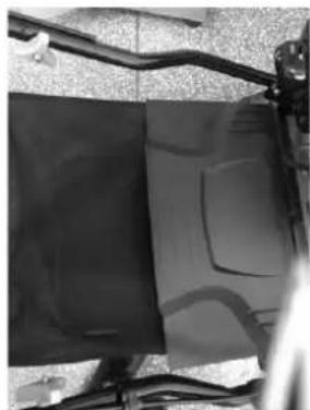
natural_image
Close-up of a black plastic panel with visible internal markings, mounted on a metal bracket (no text or symbols)natural_image
Person holding a device next to a black object, possibly a vehicle or device (no visible text or symbols)Rys. 5
GŁĘBOKOŚĆ CIĘCIA
natural_image
Close-up of a hand pressing down on a mechanical component (no visible text or symbols)Rys. 6
180. INSTRUKCJA OBSŁUGI
natural_image
Close-up of a motorcycle's drum dial with a circular knob and directional arrow (no visible text or symbols)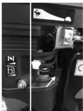
natural_image
Interior view of a vehicle showing a fuel valve and dashboard (no visible text or symbols)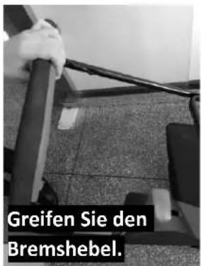
natural_image
Person in lab coat handling cables next to a dark object on carpet (no visible text or symbols)Rys.7D Rys.7E
natural_image
Close-up of a mechanical assembly with no visible text or symbolsZATRZYMAĆ SILNIKI

natural_image
Close-up of a hand holding a cable with a white arrow pointing to a component, placed on a textured surface (no visible text or symbols)Rys.8A Rys.8B

natural_image
Close-up of a black mechanical component with a circular dial and directional arrow, no visible text or symbols.ŁAPACZKI NA TRAWE
natural_image
Close-up of a black plastic enclosure with visible internal components and mounting brackets (no text or symbols)Rys.9A Rys.9B

natural_image
Close-up of hands holding a small object with a long rod, possibly a tool or device (no visible text or symbols)INSTRUKCJA REGULACJI WYSOKOŚCI

natural_image
Close-up of a car's front wheel assembly with visible tire tracks and mounting holes (no text or symbols)
natural_image
Close-up of a vehicle's roof grating system with directional arrows indicating force or movement (no text or symbols visible)Rys.11A Rys.11B
Załóż wałek.
natural_image
Close-up of a vehicle's wheel rim with visible tire tracks and directional arrows indicating motion (no text or symbols)Rys.11C
Rys.11D

natural_image
Mechanical assembly diagram showing a shaft and wheel with an arrow indicating direction (no text or symbols)Rys.11E
natural_image
Close-up of a mechanical roller or spring assembly with no visible text or symbols
natural_image
Mechanical assembly diagram showing a shaft and housing with no visible text or symbolsRyc.11G

natural_image
Close-up of a mechanical assembly with multiple gears and a central shaft, no visible text or symbolsRyc.11F
natural_image
Mechanical assembly diagram showing a multi-cranked gear mechanism with no visible text or symbolsRyc.11H
182. OPIS FUNKCJONALNY
natural_image
Illustration of a hybrid electric motor with visible blades and housing (no text or symbols)
natural_image
Orange icon of a person reading a book (no text or symbols)
Inhalt
DEUTSCHE VERSION....8
ENGLISH VERSION....25
VERSION FRANCAISE 42
POLSKA WERSJA JEZYKOWA 143
Inhalt
DEUTSCHE VERSION....8
Introduction and Security 25
- Safety Precautions.... 26
- Before the start 27
- Starting and stopping the engine 29
- Engine Maintenance.... 31
- Safety instructions for Maintenance work.... 31
- Refuelling.... 33
- Oil level measurement 34
- Oil change 35
- Air filter inspection.... 36
- Cleaning the sediment bowl.... 37
- Spark plug maintenance: 37
- Helpful hints and tips.... 38
- Petrol 39
- Engine oil 40
- Machine transport.... 41
VERSION FRANCAISE 42
POLSKA WERSJA JEZYKOWA 143
natural_image
Line drawing of a hand holding a small mechanical component (no text or symbols)
text_image
(2) (3)
text_image
Technical diagram of a vehicle engine with labeled parts including lever, valve, and housing componentstext_image
Technical diagram of a mechanical assembly with numbered components for identificationtext_image
Close-up of a vehicle electrical switch panel with red circular annotations highlighting key components.natural_image
Close-up of a mechanical assembly with a red box highlighting a component (no visible text or symbols)natural_image
Close-up of a rotary switch with 'OFF' and 'ON' labels, no readable text or symbols beyond the control buttons.text_image
EINFÜLLDECKEL/PEILSTAB OBERGRENZE IWARNUNG!
text_image
Technical diagram of a mechanical assembly with numbered components for identificationtext_image
DRAIN BOLT SEDIMENT CUPIntroduction and Security
IMPORTANT SAFETY INFORMATION
Most accidents involving engines can be avoided if you follow all the instructions in this manual and on the engine. Some of the most common hazards are illustrated below and it is explained how you can best protect yourself and others.
Owner's responsibility
- Our motors are designed for safe and reliable operation when used according to instructions. Read and understand these instructions before using the motor. Failure to follow these instructions may result in injury or damage to equipment.
- You need to know how to switch off the engine quickly and how to operate all controls. Do not allow anyone to operate the engine without proper instructions.
- Do not allow children to operate the engine. Keep children and pets from the work area.
Refuelling with care
Petrol is highly flammable and petrol vapours can explode. Fuel up outdoors, in a well-ventilated area and with the engine switched off. Never smoke near petrol and keep other flames and sparks away. Always store petrol in an approved container. If you spill petrol, make sure the area is dry before starting the engine.
Hot exhaust
- The exhaust/muffler becomes very hot during operation and remains hot for some time after the engine is switched off. Take care not to touch the silencer when it is hot. Allow the engine to cool down before parking it indoors.
- During operation, keep the motor at least 1 metre away from the walls of the building and other equipment to avoid fire hazards and to ensure adequate ventilation of fixed equipment. Do not place flammable objects near the motor.
Carbon monoxide hazard
Exhaust gases contain poisonous carbon monoxide. Avoid inhaling the exhaust fumes. Never leave the engine running in a garage or enclosed space.
Other devices
Read the instructions supplied with the unit powered by this engine for additional safety precautions to be observed in connection with starting, stopping and operating the engine, or for protective clothing that may be required to operate the unit.
Position of security stickers
These stickers warn of possible dangers that can cause serious injury. Read them carefully.
If a sticker becomes detached or difficult to read, please contact FUXTEC for replacement.
17. Safety Precautions
- When the engine is running, exhaust gases contain carbon monoxide. To avoid accidents, the engine must not be used indoors. Otherwise you run the risk of suffocation.
- Flammable, explosive and other hazardous substances must be kept well away from the engine. There must be no naked flames in the vicinity of the engine.
- The engine must be switched off when refuelling with fuel and lubricating oil. Smoking is not permitted. If fuel or lubricating oil overflows or leaks, it must be thoroughly cleaned before starting the engine.
- The use of the engine by unqualified persons is strictly forbidden.
18. Before the start
The engine is delivered to the customer without oil and petrol. Both fluids must be filled by the user before the engine is used for the first time. If there is still oil on the dipstick before the first filling, this is due to the factory test, where each engine is started once to be checked. All operating fluids are then extracted to make the engine ready for transport. A slight film of oil does not mean that the engine contains enough. Be sure to top it up before the first start-up.
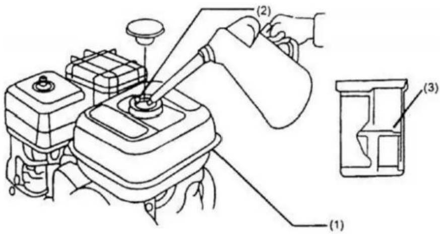
- Checking and topping up the engine oil level
Switch off the engine and check the engine oil level. Unscrew the oil dipstick to check whether the engine oil level is within the specified range. If the oil level is too low, top up the engine oil to the specified level (see figures below). For this purpose, use at least 15W/40SAE engine oil.
(2) = maximum engine oil fill level
(3) = minimum engine oil fill level
natural_image
Line drawing of a hand operating a mechanical device with a circular component (no text or symbols)
text_image
(2) (3)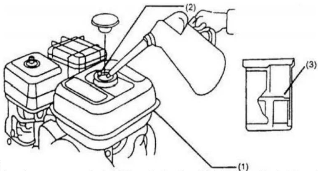
text_image
Technical diagram showing a mechanical assembly with labeled parts (1), (2), and (3) indicating different components or functions.• R
This engine runs on normal petrol. If the petrol tank level (1) is too low, add petrol through the filler neck (2) Add oil until the red mark (3) on the inside of the filter is reached (see figure below).
Do not mix petrol with engine oil.
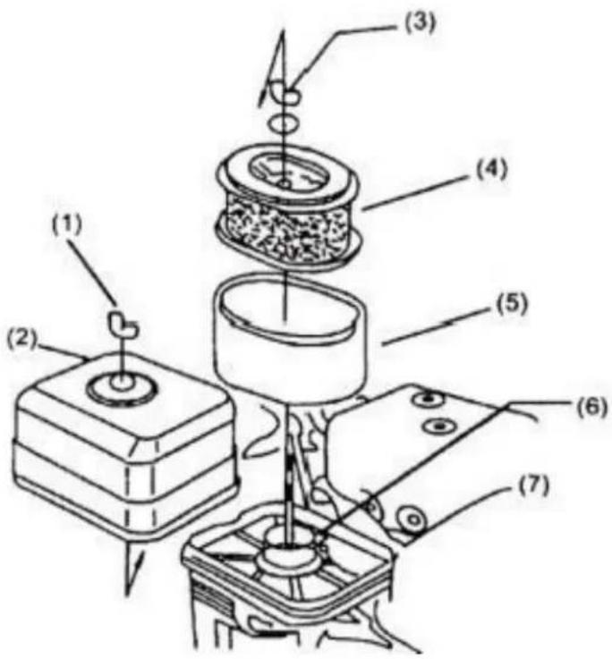
- Checking the Air Filter
This air filter is a dry filter and contains two filter elements.
A paper filter and a foam filter. To check the filter elements, remove the air filter housing (see illustration below).
If the filter elements are dirty, clean them with water.
Important: completely and gently air dry both filters before re-use.
text_image
Technical diagram of a mechanical assembly with numbered components for identification(1) = wing nut
(2) = Air filter box
(3) = wing nut
(4) = Paper filter
(5) = Foam filter
(6) = Sealing ring
(7) = air filter box
19. Starting and stopping the engine
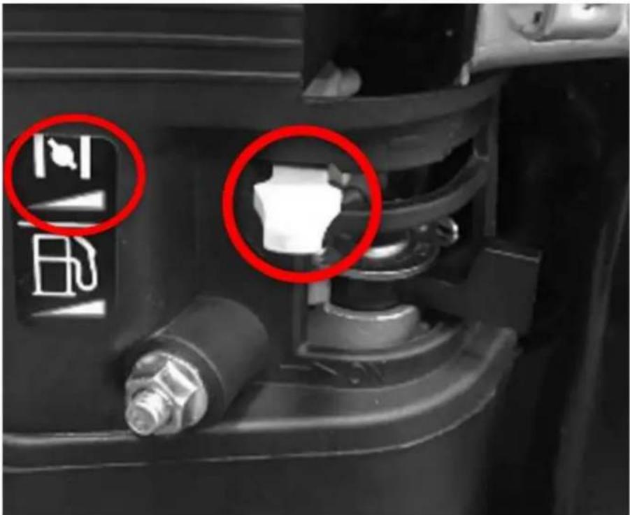
When starting the engine cold, close the choke and open the petrol tap. (see figure below).
text_image
Close-up of a vehicle engine component with red circular annotations highlighting features like fuel and valve symbols.Turn the motor switch to the 'ON' position (see figure below).
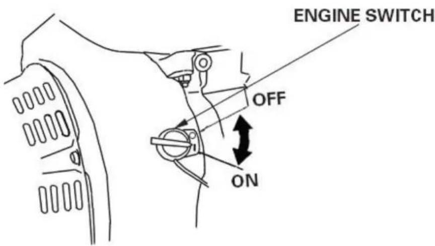
text_image
ENGINE SWITCH OFF ONAt this point, gently pull on the starter cable until you feel a slight resistance. This is the starting
position for pulling hard and starting the engine. (see illustration below).
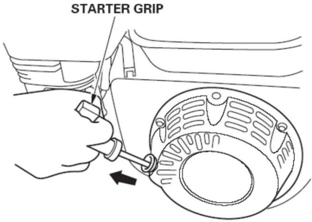
text_image
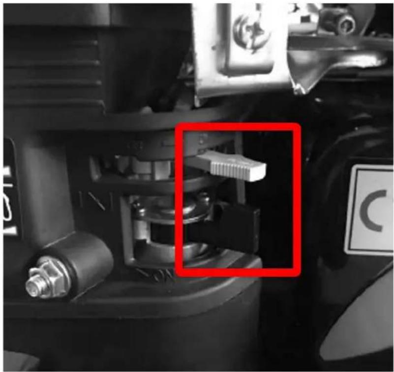
STARTER GRIPWhen the engine is running, slowly open the throttle/choke without shutting down the engine (see illustration below).
natural_image
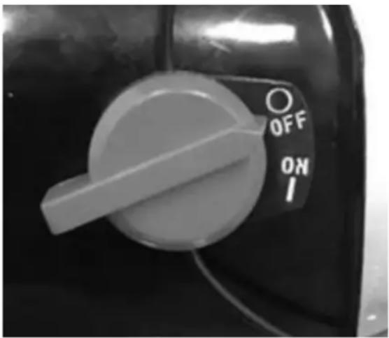
Close-up of a mechanical assembly with a red box highlighting a component, no visible text or symbolsTo stop the engine, turn the engine switch to the 'OFF' position.
natural_image
Close-up of a rotary switch with 'OFF' and 'ON' labels, no readable text or symbols beyond the control buttons.20. Engine Maintenance
Good maintenance is essential for safe, economical and trouble-free operation. It also helps reduce air pollution.
WARNING:
Improper maintenance of this motor or failure to correct a problem before use may result in a malfunction that can seriously injure or kill the user.
Always follow the recommendations and inspection and maintenance schedules in these operating instructions.
21. Safety instructions for Maintenance work
The following pages list some of the most important safety precautions. However, we cannot warn you of all possible dangers that may occur when performing maintenance work. Only you can decide whether or not to carry out a certain operation.
WARNING:
Serious injury or death can occur if maintenance instructions and precautions are not followed correctly. Always follow the procedures and precautions indicated in the instructions for use.
Safety precautions:
- Make sure the engine is switched off before starting maintenance or repair work. Repair avoids several potential risks
- Carbon monoxide intoxication from engine exhaust fumes. Ensure adequate ventilation during engine operation.
- Burns caused by hot parts. Let the engine and exhaust system cool down before touching them.
- Injuries due to moving parts. Do not start the engine unless instructed to do so.
- Read the instructions before starting and make sure you have the necessary tools and skills.
- Take care when working near petrol to reduce the risk of fire or explosion. fire or explosion. Only use a non-flammable solvent. solvent
To ensure the highest quality and reliability, use only new original spare parts from our company. For repairs and replacements, use only new original spare parts from our company or equivalent spare parts.
text_image
(1) (2) (3)22. Refuelling
Refuelling in a well-ventilated area before starting the engine. If the engine is already running, allow it to cool down. Refuel carefully to avoid spilling fuel.
Do not fill the tank beyond the mark on the fuel filter. After refuelling, tighten the tank cap securely.
Never refuel your engine in a building where petrol vapours can reach flames or sparks. can reach you. Keep petrol away from flames, barbecues, electrical appliances, etc, power tools, etc.
Spilled petrol is not only a fire hazard, but also causes damage to the environment.
Clean up spilled petrol immediately.
NOTE:
Fuel can damage paint and plastic. When filling the tank, take care not to spill fuel outside. Damage caused by spilled fuel is not covered by the warranty.
Use unleaded petrol with an octane rating of 95 or higher.
These engines are approved for operation with unleaded petrol. Unleaded petrol reduces deposits.
Fewer deposits in the engine and spark plugs prolong the life of the exhaust system.
Never use old or contaminated petrol or an oil/gasoline mixture.
Do not allow dirt or water to enter the fuel tank.
Occasionally a slight spark or ping (metallic knocking noise) may be heard when the engine is under load. This is not a cause for concern.
If sparks or knocks occur at constant speed and under normal load, change the brand of petrol.
If sparks or knocks continue to occur, please contact a specialist workshop.
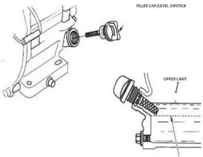
23. Oil level measurement
Check the engine oil level with the engine switched off and in a horizontal position.
Remove the filler cap/tape and clean it.
Insert the dipstick and remove it without screwing it into the filler neck. Check the oil level indicated on the dipstick.
- if the oil level is low, top up with the recommended oil to the edge of the filler neck.
4 Screw the filler cap/tape on firmly.
text_image
FILLER CAP/LEVEL DIPSTICK UPPER LIMIT IWARNING:
Do not operate the engine if the oil level is too low. This may cause irreparable damage.
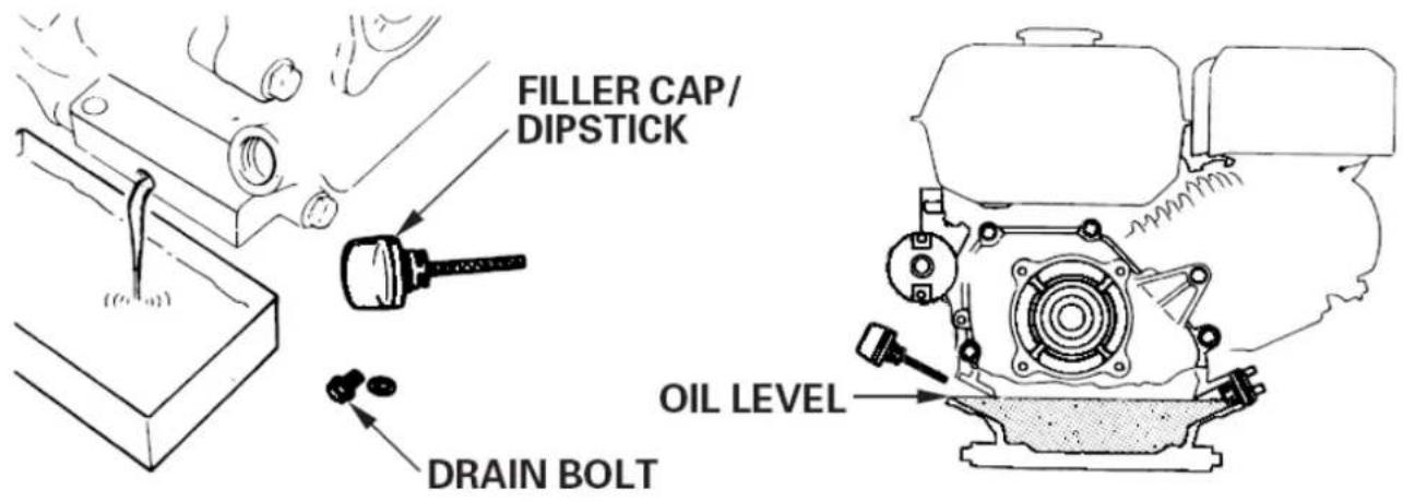
24. Oil change
Drain the used oil when the engine is hot. Hot oil drains quickly and completely.
- place a suitable container under the engine to collect used oil
- and then remove the filler/tap and drain plug.
- Allow the used oil to drain completely, then reinsert the drain plug and tighten it firmly.
- Dispose of used engine oil in an environmentally friendly manner. We recommend disposing of used oil in a sealed container at the recycling centre or service station for recovery. Do not throw it in the rubbish or pour it on the floor or down a drain.
- With the engine in a horizontal position, fill the recommended oil up to the outer edge of the oil filling opening.
• 4 Screw the filler cap/tape on firmly.
text_image
FILLER CAP/ DIPSTICK DRAIN BOLT OIL LEVELUse the following engine oil, depending on the ambient temperature:
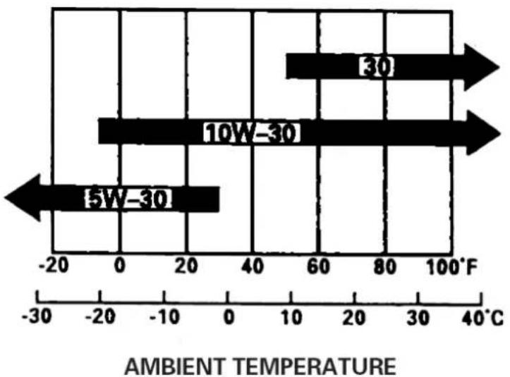
bar
| Range | Temperature (°C) | |---|---| | 5W-30 | -20 | | 10W-30 | 0 | | 30 | 60 |25. Air filter inspection
Remove the air filter cover and inspect the filter. Clean or replace dirty filter elements. Damaged filter elements must always be replaced.

text_image
Technical diagram of a mechanical assembly with numbered components for identificationA dirty air filter restricts air flow to the carburettor and reduces the performance of the engine. If you use the engine in a very dusty environment, it is best to clean the air filter after each use.
Running the engine without an air filter or with a damaged air filter causes dirt to build up. in the engine and causes it to wear out quickly. This type of damage is not covered by the warranty.
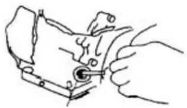
26. Cleaning the sediment bowl
- Turn the fuel tap to the OFF position and then remove the fuel sediment container and the O-ring. fuel sediment container and the O-ring.
- Wash the sediment container and the O-ring with a non-flammable solvent and dry them thoroughly.
- Insert the O-ring into the fuel valve and install the sediment container. Tighten the sediment container securely.
- Turn the fuel tap to the ON position and check for leaks. Replace the O-ring in case of leakage.
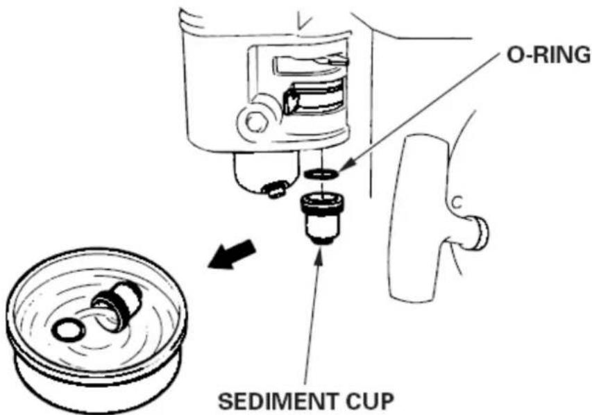
text_image
O-RING SEDIMENT CUP27. Spark plug maintenance:
- Remove the spark plug connector and remove dirt from the spark plug area.
- Remove the spark plug with a suitable spanner.
- Check the spark plug. Replace it if the electrodes are worn or if the insulation is cracked or chipped.
- Measure the distance between the spark plug electrodes with a suitable gauge. The distance should be between 0.6 and 0.7 mm. If necessary, correct the distance by carefully bending the side electrode.
- Insert the spark plug carefully and by hand to avoid over-tightening it.
• After inserting the spark plug, tighten it with a suitable spark plug spanner. - When refitting the used spark plug, tighten the spark plug 1/8 - 1/4 turn after the spark plug has been inserted.
- When installing a new spark plug tighten it 1/2 turn after the spark plug
spark plug has been inserted.
- A loose spark plug can overheat and damage the engine. If you tighten the spark plug too much, the cylinder head thread may be damaged.
- Mount the spark plug cap.
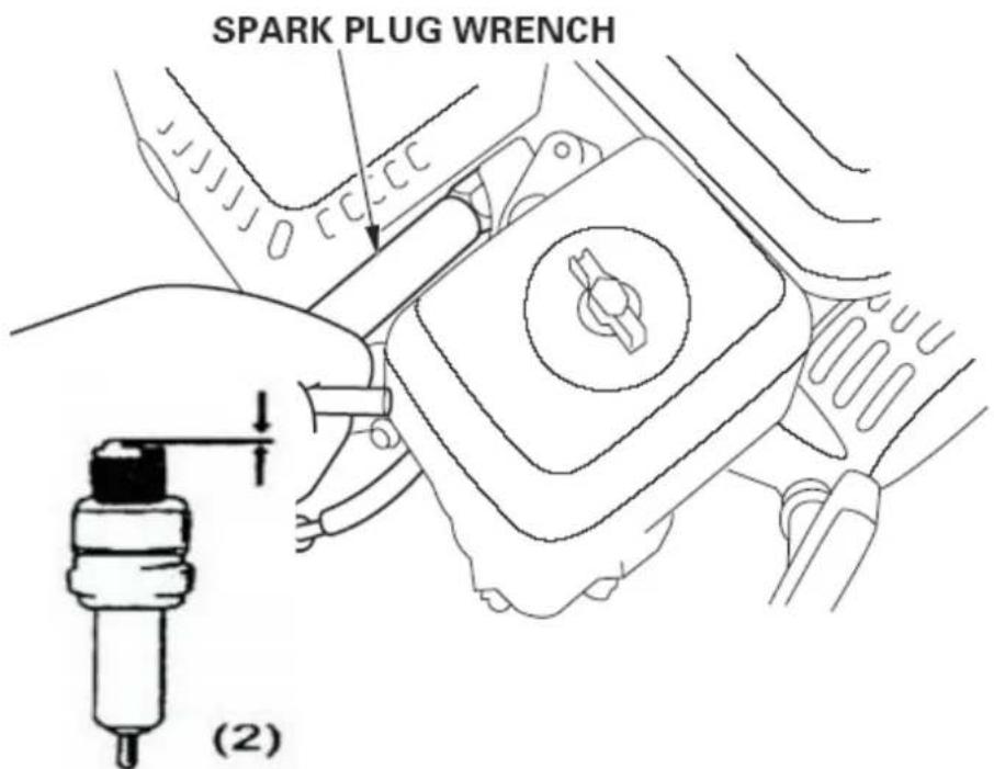
text_image
SPARK PLUG WRENCH (2)0.6 mm - 0.7 mm
0.028 - 0.03 inch
28. Helpful hints and tips
Proper preparation for storage is essential to ensure that the engine runs smoothly and looks good. The following steps will help ensure that rust and corrosion do not affect the engine's function and appearance and that the engine is easier to start after storage.
Important note:
When using a garden hose or a pressure washer, water can penetrate the air filter or the muffler opening. Water in the air filter impregnates the filter and water that passes through the air filter or silencer can enter the cylinder and cause damage.
Water coming into contact with a hot engine can cause damage. If the engine has been running, let it cool for at least half an hour before cleaning it.
29. Petrol
Petrol oxidises and deteriorates during storage.
Old petrol causes starting difficulties and leaves deposits
which can clog the fuel system.
If the petrol in the engine deteriorates during storage, it may be necessary to
have the carburettor and other fuel system components repaired or replaced.
How long petrol remains in the tank and carburettor without malfunctioning depends on factors such as the petrol mixture, fuel, storage temperatures and whether or not there is fuel in the tank.
Air in a partially filled tank promotes fuel deterioration.
Very hot storage temperatures accelerate fuel deterioration. Fuel deterioration problems can occur within a few months, or even sooner if the petrol was not fresh when the tank was filled.
The dealer's limited warranty does not cover damage to the fuel system or engine performance. engine performance problems caused by negligent stock preparation.
preparation.
It is recommended to completely empty the tank and carburettor before storing the vehicle for an extended period of time.
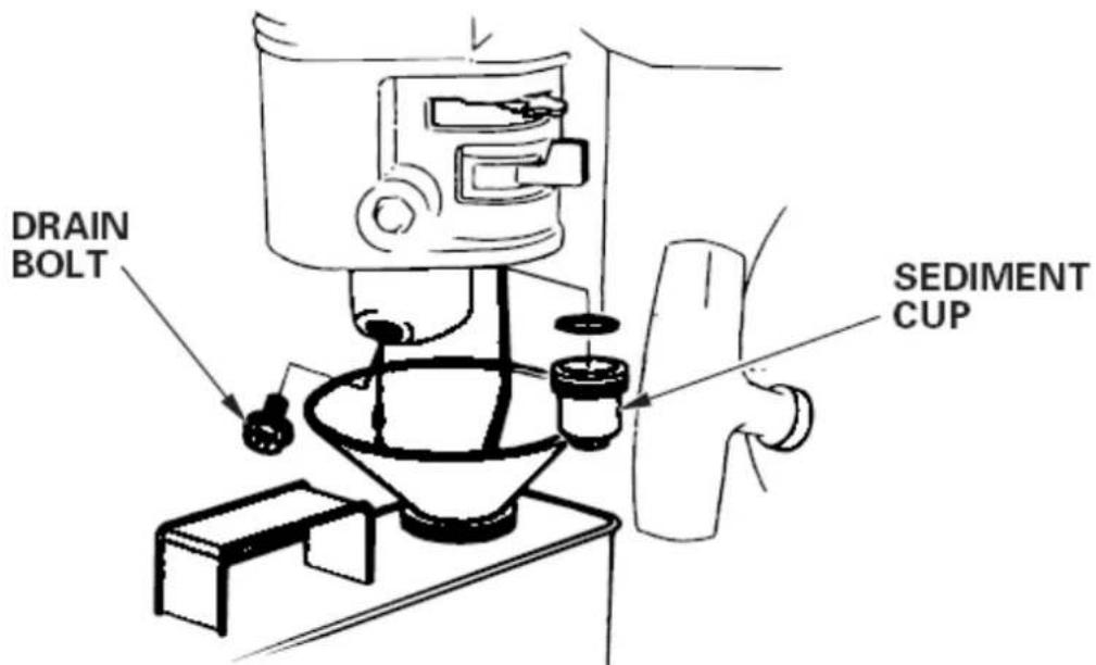
text_image
DRAIN BOLT SEDIMENT CUP- Place an approved petrol container under the carburettor and use a funnel to avoid spilling fuel.
- Remove the carburettor drain plug and sediment container and turn the fuel valve lever to the ON position.
- Once all the fuel has been drained into the container, replace the drain plug and the storage container. Tighten them securely.
30. Engine oil
- Change engine oil.
- Remove the spark plugs.
• Pour a tablespoon (5-10 cm ^3 ) of clean engine oil into the cylinder.
• Pull the starter rope several times to distribute the oil in the cylinder. - Reinsert the spark plugs.
- Slowly pull the starter rope until resistance is felt and the notch on the starter disc is aligned with the hole on the top of the recoil starter cover.
This closes the valves to prevent moisture entering the engine cylinder. - Carefully pull back the starter rope.
If the engine is stored with petrol in the tank and carburettor, it is important to reduce the risk of ignition of petrol vapours. Choose a storage area that is well ventilated and not close to appliances that operate with a flame, such as ovens, water heaters or dryers. Also avoid areas where spark-generating electric motors or power tools are in operation.
We recommend storing the machine as described in the petrol section, without petrol in the tank.
If possible, avoid storage areas with high humidity, as they promote rust and corrosion.
Unless all the fuel has been drained from the tank, leave the fuel valve lever in the OFF position to minimise the possibility of fuel leakage.
Position the unit so that the engine is level. Tipping can cause fuel or oil leaks.
When the engine and exhaust system are cold, cover the engine to protect it from dust.
A hot engine and exhaust system can ignite or melt certain materials. Do not use plastic sheeting as a dust cover. A non-porous cover retains moisture around the engine and promotes rust and corrosion.
If fuel has been drained during preparation for storage, fill the tank with fresh petrol immediately before using it again. If you store a petrol tank for refuelling, ensure that it contains only fresh petrol. that it contains only fresh petrol. Petrol oxidises and deteriorates over time, causing starting
difficulties.
If the cylinders have been coated with oil during preparation for storage, the engine may smoke briefly when starting. This is normal.
31. Machine transport
If the engine has been started, allow it to cool down for at least 15 minutes before loading the machine onto the transport vehicle. A hot engine and exhaust system can cause burns and ignite certain materials.
Keep the engine level during transport to minimise the possibility of fuel leakage.
Turn the fuel valve lever to the OFF position.
VERSION FRANCAISE
natural_image
Line drawing of a hand operating a mechanical device with a circular component (no text or symbols)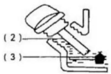
text_image
(2) (3)
text_image
Technical diagram of a mechanical assembly with labeled parts (1), (2), and (3), showing tool path and component layout.text_image
Technical diagram of a mechanical assembly with numbered components for identificationtext_image
Close-up of a vehicle battery terminal with red circular annotations highlighting fuel efficiency symbolsnatural_image
Close-up of a mechanical assembly with a red box highlighting a component (no visible text or symbols)natural_image
Close-up of a rotary switch with 'OFF' and 'ON' labels, no readable text or symbols beyond the control buttons.text_image
Technical diagram of a mechanical assembly with numbered components for identificationtext_image
DRAIN BOLT SEDIMENT CUPnatural_image
Line drawing of a hand operating a mechanical device with a circular component (no text or symbols)
text_image
(2) (3)
text_image
Technical diagram showing a mechanical assembly with labeled parts (1), (2), and (3), including a hand pouring liquid into a container.text_image
Technical diagram of a mechanical assembly with numbered components for identificationtext_image
Close-up of a vehicle electrical switch panel with red circular annotations highlighting specific components.natural_image
Close-up of a mechanical assembly with a highlighted component (no visible text or symbols)natural_image
Close-up of a rotary switch with 'OFF' and 'ON' labels, no readable text or symbols beyond the control buttons.text_image
Technical diagram of a mechanical assembly with numbered components for identificationtext_image
DRAIN BOLT SEDIMENT CUPnatural_image
Line drawing of a hand using a tool to adjust or install a mechanical component (no text or symbols present)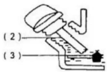
text_image
(2) (3)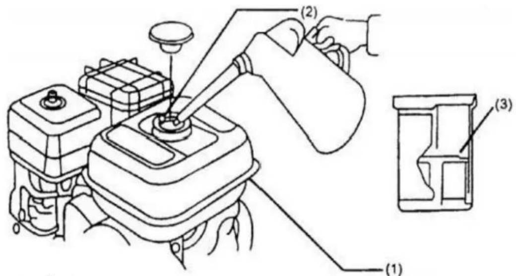
text_image
Technical diagram showing a mechanical assembly with labeled parts (1), (2), and (3) indicating different components or functions.- Repostar el motor
text_image
Technical diagram of a mechanical assembly with numbered components for identification(1) = tuerca de mariposa
(2) = Caja del filtro de aire
(3) = tuerca de mariposa
(4) = Filtro de papel
(5) = Filtro de espuma
(6) = Junta de estanqueidad
(7) = Caja del filtro de aire
text_image
Close-up of a vehicle fuel switch panel with red circular annotations highlighting specific components.natural_image
Close-up of a mechanical assembly with a red box highlighting a component (no visible text or symbols)natural_image
Close-up of a rotary switch with 'OFF' and 'ON' labels, no readable text or symbols beyond the control buttons.text_image
Technical diagram of a mechanical assembly with numbered components for identificationtext_image
DRAIN BOLT SEDIMENT CUPnatural_image
Line drawing of a hand using a tool to adjust or install a mechanical component (no text or symbols present)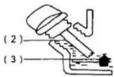
text_image
(2) (3)
text_image
Technical diagram of a vehicle engine with labeled parts including lever, valve, and housing componentstext_image
Technical diagram of a mechanical assembly with numbered components for identificationtext_image
Close-up of a vehicle engine component with red circular annotations highlighting features like fuel and valve symbols.natural_image
Line drawing of a car wheel assembly with a hand adjusting the component (no text or symbols)natural_image
Close-up of a mechanical assembly with a red box highlighting a component, no visible text or symbolsnatural_image
Close-up of a rotary switch with 'OFF' and 'ON' labels, no readable text or symbols beyond the control buttons.text_image
Technical diagram of a mechanical assembly with numbered components for identificationtext_image
DRAIN BOLT SEDIMENT CUPnatural_image
Line drawing of a hand operating a mechanical device with a circular component (no text or symbols)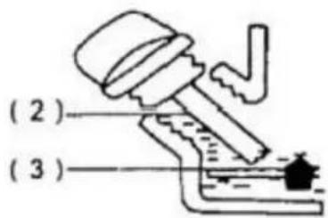
text_image
(2) (3)
text_image
Technical diagram showing a mechanical assembly with labeled parts (1), (2), and (3), including a hand pouring liquid into a container.- Motor bijvullen
text_image
Technical diagram of a mechanical assembly with numbered components for identification(1) = vleugelmoer
(2) = Luchtfilterkast
(3) = vleugelmoer
(4) = Papieren filter
(5) = Schuimfilter
(6) = Afdichtring
(7) = luchtfilterkast
99. De motor starten en stoppen
text_image
Close-up of a vehicle fuel switch panel with red circular annotations highlighting specific components.natural_image
Close-up of a mechanical assembly with a red box highlighting a component, no visible text or symbolsOm de motor te stoppen, zet u de motorschakelaar in de stand 'UIT'.

natural_image
Close-up of a rotary switch with 'OFF' and 'ON' labels, no readable text or symbols beyond the control buttons.text_image
Technical diagram of a mechanical assembly with numbered components for identificationtext_image
DRAIN BOLT SEDIMENT CUPnatural_image
Line drawing of a hand operating a mechanical device with a circular component (no text or symbols)
text_image
(2) (3)
text_image
Technical diagram showing a mechanical assembly with labeled parts (1), (2), and (3), including a hand pouring liquid into a container.text_image
Technical diagram of a mechanical assembly with numbered components for identification(1) = vingmutter
(2) = Luftfilterbox
(3) = vingmutter
(4) = Pappersfilter
(5) = Skumfilter
(6) = Tätningsring
(7) = Luftfilterlåda
text_image
Close-up of a vehicle engine component with red circular annotations highlighting features like fuel and valve symbols.natural_image
Close-up of a mechanical assembly with a red box highlighting a component, no visible text or symbolsnatural_image
Close-up of a rotary switch with 'OFF' and 'ON' labels, no readable text or symbols beyond the control buttons.text_image
Technical diagram of a mechanical assembly with numbered components for identificationtext_image
DRAIN BOLT SEDIMENT CUPPOLSKA WERSJA JEZYKOWA
natural_image
Line drawing of a hand operating a mechanical device with a circular component (no text or symbols)
text_image
(2) (3)