PO5000C - Polisher MAKITA - Free user manual and instructions
Find the device manual for free PO5000C MAKITA in PDF.

| Product type | Random orbital polisher |
| Brand | Makita |
| Model | PO5000C |
| Pad diameter | 125 mm |
| Number of orbits per minute | 0 - 6,800 min⁻¹ |
| Overall length | 451 mm |
| Net weight | 2.8 - 3.0 kg |
| Protection class | Double insulation (Class II) |
| Power supply | Single phase, mains voltage (according to rating plate) |
| Sound pressure level | 81 dB(A) |
| Sound power level | 92 dB(A) |
| Vibration emission (polishing) | 6.5 m/s² |
| Vibration uncertainty (K) | 1.5 m/s² |
| Variable speed | Yes, speed control dial from 1 to 5 |
| Electronic functions | Constant speed control, soft start |
| Operating modes | Forced rotation eccentric and free eccentric |
| Side handle | Optional, on both sides |
| Removable dust guards | Yes, to be cleaned regularly |
| Supplied accessories | Backing pad, foam pad (depending on country) |
| Optional accessories | Wool pad, felt pad |
| Maintenance | Cleaning dust guards, service at Makita authorized center |
| Reparability | Spare parts and after-sales service by Makita |
| Application | Surface polishing |
Frequently Asked Questions - PO5000C MAKITA
User questions about PO5000C MAKITA
0 question about this device. Answer the ones you know or ask your own.
Ask a new question about this device
Download the instructions for your Polisher in PDF format for free! Find your manual PO5000C - MAKITA and take your electronic device back in hand. On this page are published all the documents necessary for the use of your device. PO5000C by MAKITA.
USER MANUAL PO5000C MAKITA
natural_image
Line drawing of a mechanical power tool with a long shaft and multiple blades (no text or symbols)

natural_image
Medical illustration showing a cross-sectional view of a mechanical device with internal components and a magnified inset (no text or symbols)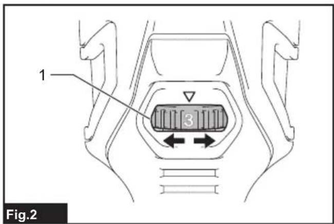
natural_image
Technical line drawing of a power tool with labeled component (1), no text or symbols present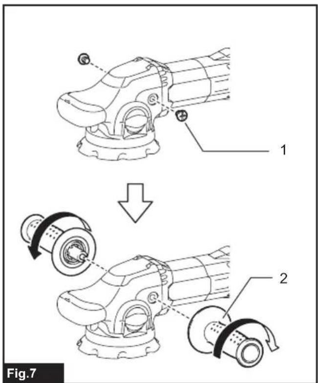
natural_image
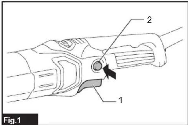
Line drawing of a person using a power tool on a car wheel (no text or symbols)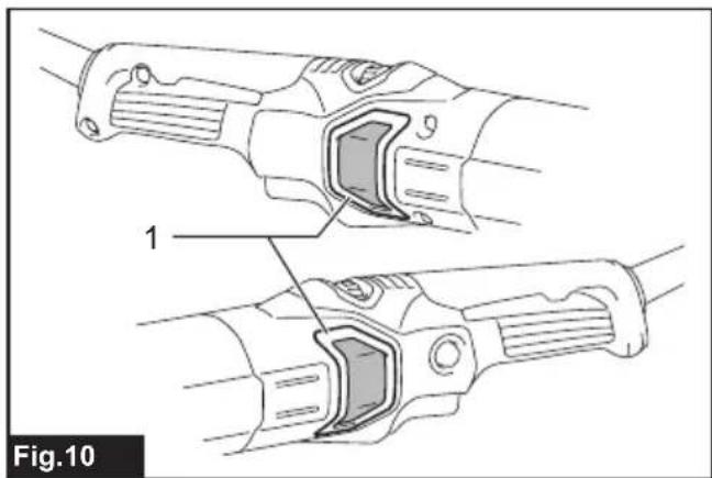
natural_image
Technical line drawing of two mechanical components with labeled parts (no text or symbols present)SPECIFICATIONS
| Model: PO5000C PO6000C | ||
| Pad diameter 125 mm 150 mm | ||
| Orbits per minute 0 - 6,800 min | -1 | |
| Overall length 451 mm | ||
| Net weight 2.8 - 3.0 kg | ||
| Safety class | ☐/II | |
- Due to our continuing program of research and development, the specifications herein are subject to change without notice.
• Specifications may differ from country to country. - The weight may differ depending on the attachment(s). The lightest and heaviest combination, according to EPTA-Procedure 01/2014, are shown in the table.
Intended use
The tool is intended for polishing.
Power supply
The tool should be connected only to a power supply of the same voltage as indicated on the nameplate, and can only be operated on single-phase AC supply. They are double-insulated and can, therefore, also be used from sockets without earth wire.
Noise
The typical A-weighted noise level determined according to EN62841:
Model PO5000C
Sound pressure level ( L_pA ): 81 dB(A)
Sound power level ( L_WA ): 92 dB (A)
Uncertainty (K) : 3 dB(A)
Model PO6000C
Sound pressure level ( L_pA ): 83 dB(A)
Sound power level (LWA): 94 dB (A)
Uncertainty (K) : 3 dB(A)

WARNING: Wear ear protection.
Vibration
The vibration total value (tri-axial vector sum) determined according to EN62841:
Model PO5000C
Work mode: polishing
Vibration emission ( a_h,P ): 6.5 m/s ^2
Uncertainty (K) : 1.5 m/s²
Model PO6000C
Work mode: polishing
Vibration emission ( a_h,P ): 7.0 m/s ^2
Uncertainty (K) : 1.5 m/s²
NOTE: The declared vibration emission value has been measured in accordance with the standard test method and may be used for comparing one tool with another.
NOTE: The declared vibration emission value may also be used in a preliminary assessment of exposure.

WARNING: The vibration emission during actual use of the power tool can differ from the declared emission value depending on the ways in which the system is used.

WARNING: Be sure to identify safety measures protect the operator that are based on an estimation of exposure in the actual conditions of use (taking account of all parts of the operating cycle such as times when the tool is switched off and when it is turning idle in addition to the trigger time).
EC Declaration of Conformity
For European countries only
The EC declaration of conformity is included as Annex A to this instruction manual.
SAFETY WARNINGS
General power tool safety warnings

WARNING: Read all safety warnings, instructs, illustrations and specifications provided with this power tool. Failure to follow all instructions ed below may result in electric shock, fire and/orious injury.
Save all warnings and instructions for future reference.
The term "power tool" in the warnings refers to your mains-operated (corded) power tool or battery-operated (cordless) power tool.
Polisher safety warnings
- This power tool is intended to function as a polisher. Read all safety warnings, instructions, illustrations and specifications provided with this power tool. Failure to follow all instructions listed below may result in electric shock, fire and/or serious injury.
- Operations such as grinding, wire brushing or cutting-off are not recommended to be performed with this power tool. Operations for which the power tool was not designed may create a hazard and cause personal injury.
- Do not use accessories which are not specifically designed and recommended by the tool manufacturer. Just because the accessory can be attached to your power tool, it does not assure safe operation.
- The rated speed of the accessory must be at least equal to the maximum speed marked on the power tool. Accessories running faster than their rated speed can break and fly apart.
- The outside diameter and the thickness of your accessory must be within the capacity rating of your power tool. Incorrectly sized accessories cannot be adequately guarded or controlled.
- Threaded mounting of accessories must match the spindle thread. For accessories mounted by flanges, the arbour hole of the accessory must fit the locating diameter of the flange. Accessories that do not match the mounting hardware of the power tool will run out of balance, vibrate excessively and may cause loss of control.
- Do not use a damaged accessory. Before each use inspect the accessory such as backing pad for cracks, tear or excess wear. If power tool or accessory is dropped, inspect for damage or install an undamaged accessory. After inspecting and installing an accessory, position yourself and bystanders away from the plane of the rotating accessory and run the power tool at maximum no-load speed for one minute. Damaged accessories will normally break apart during this test time.
- Wear personal protective equipment. Depending on application, use face shield, safety goggles or safety glasses. As appropriate, wear dust mask, hearing protectors, gloves and workshop apron capable of stopping small abrasive or workpiece fragments. The eye protection must be capable of stopping flying debris generated by various operations. The dust mask or respirator must be capable of filtrating particles generated by your operation. Prolonged exposure to high intensity noise may cause hearing loss.
-
Keep bystanders a safe distance away from work area. Anyone entering the work area must wear personal protective equipment. Fragments of workpiece or of a broken accessory may fly away and cause injury beyond immediate area of operation.
-
Position the cord clear of the spinning accessory. If you lose control, the cord may be cut or snagged and your hand or arm may be pulled into the spinning accessory.
- Never lay the power tool down until the accessory has come to a complete stop. The spinning accessory may grab the surface and pull the power tool out of your control.
- Do not run the power tool while carrying it at your side. Accidental contact with the spinning accessory could snag your clothing, pulling the accessory into your body.
- Regularly clean the power tool's air vents. The motor's fan will draw the dust inside the housing and excessive accumulation of powdered metal may cause electrical hazards.
- Do not operate the power tool near flammable materials. Sparks could ignite these materials.
- Do not use accessories that require liquid coolants. Using water or other liquid coolants may result in electrocution or shock.
Kickback and Related Warnings
Kickback is a sudden reaction to a pinched or snagged rotating wheel, backing pad, brush or any other accessory. Pinching or snagging causes rapid stalling of the rotating accessory which in turn causes the uncontrolled power tool to be forced in the direction opposite of the accessory's rotation at the point of the binding. For example, if an abrasive wheel is snagged or pinched by the workpiece, the edge of the wheel that is entering into the pinch point can dig into the surface of the material causing the wheel to climb out or kick out. The wheel may either jump toward or away from the operator, depending on direction of the wheel's movement at the point of pinching. Abrasive wheels may also break under these conditions.
Kickback is the result of power tool misuse and/or incorrect operating procedures or conditions and can be avoided by taking proper precautions as given below.
- Maintain a firm grip on the power tool and position your body and arm to allow you to resist kickback forces. Always use auxiliary handle, if provided, for maximum control over kickback or torque reaction during start-up. The operator can control torque reactions or kickback forces, if proper precautions are taken.
- Never place your hand near the rotating accessory. Accessory may kickback over your hand.
- Do not position your body in the area where power tool will move if kickback occurs. Kickback will propel the tool in direction opposite to the wheel's movement at the point of snagging.
- Use special care when working corners, sharp edges etc. Avoid bouncing and snagging the accessory. Corners, sharp edges or bouncing have a tendency to snag the rotating accessory and cause loss of control or kickback.
- Do not attach a saw chain woodcarving blade or toothed saw blade. Such blades create frequent kickback and loss of control.
Safety Warnings Specific for Polishing Operations
- Do not allow any loose portion of the polishing bonnet or its attachment strings to spin freely. Tuck away or trim any loose attachment strings. Loose and spinning attachment strings can entangle your fingers or snag on the workpiece.
Additional Safety Warnings
- Do not leave the tool running. Operate the tool only when hand-held.
- Check that the workpiece is properly supported.
- If working place is extremely hot and humid, or badly polluted by conductive dust, use a short-circuit breaker (30 mA) to assure operator safety.
- Do not use the tool on any materials containing asbestos.
SAVE THESE INSTRUCTIONS.
WARNING: DO NOT let comfort or familiarity with product (gained from repeated use) replace strict adherence to safety rules for the subject product. MISUSE or failure to follow the safety rules stated in this instruction manual may cause serious personal injury.
FUNCTIONAL DESCRIPTION
CAUTION: Always be sure that the tool is switched off and unplugged before adjusting or checking function on the tool.
Switch action
⚠️ CAUTION: Before plugging in the tool, always check to see that the switch trigger actuates properly and returns to the "OFF" position when released.
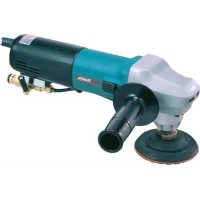
▶ Fig.1: 1. Switch trigger 2. Lock button
To start the tool, simply pull the switch trigger. The rotation speed will increase as you pull the trigger. Release the switch trigger to stop. For continuous operation, pull the switch trigger, push in the lock button and then release the switch trigger. To stop the tool from the locked position, pull the trigger fully, then release it.
CAUTION: Switch can be locked in "ON" position for ease of operator comfort during extended use. Apply caution when locking tool in "ON" position and maintain firm grasp on tool.
⚠️ CAUTION: Do not plug in the tool with the lock-on switch engaged. The tool will be run unsupported and it may cause a personal injury or breakage.
Speed adjusting dial
▶ Fig.2: 1. Speed adjusting dial
The rotating speed can be changed by turning the speed adjusting dial to a given number setting from 1 to 5. Higher speed is obtained when the dial is turned in the direction of number 5. And lower speed is obtained when it is turned in the direction of number 1. Refer to the table for the relationship between the number settings on the dial and the approximate rotating speed.
| Number Orbits per min. Pad rotating | |
| speed per minute in random orbit with forced rota-tion mode | |
| 1 1,600 180 | |
| 2 2,500 290 | |
| 3 3,700 430 | |
| 4 5,300 610 | |
| 5 6,800 780 | |
NOTICE: If the tool is operated continuously at low speeds for a long time, the motor will get overloaded, resulting in tool malfunction.
NOTICE: The speed adjusting dial can be turned only as far as 5 and back to 1. Do not force it past 5 or 1, or the speed adjusting function may no longer work.
Electronic function
The tools equipped with electronic function are easy to operate because of the following features.
Constant speed control
Possible to get fine finish, because the rotating speed is kept constant even under the loaded condition.
Soft start feature
Soft start because of suppressed starting shock.
Selecting the action mode
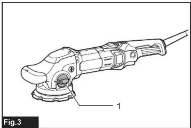
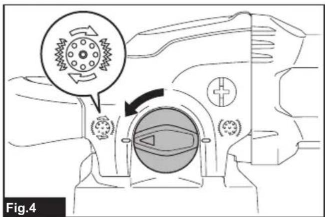
Turn the change knob to alter the rotation mode.
▶ Fig.3: 1. Change knob
NOTICE: Always turn the knob fully. If the knob is in the middle position, you can not turn on the tool.
NOTICE: You can not change the action mode when the tool is switched on.
Random orbit with forced rotation mode
▶ Fig.4
Random orbit with forced rotation mode is orbital action with forced rotation of the pad for rough polishing such as surface treatment.
Rotate the change knob counterclockwise for random orbit with forced rotation mode.
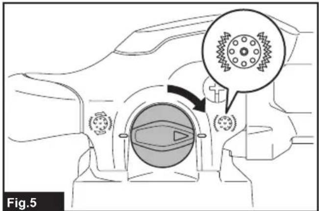
Random orbit mode
▶ Fig.5
Random orbit mode is orbital action with free rotation of the pad for fine polishing.
Rotate the change knob clockwise for random orbit mode.
ASSEMBLY
⚠️CAUTION: Always be sure that the tool is switched off and unplugged before carrying out any work on the tool.
Installing the backing pad
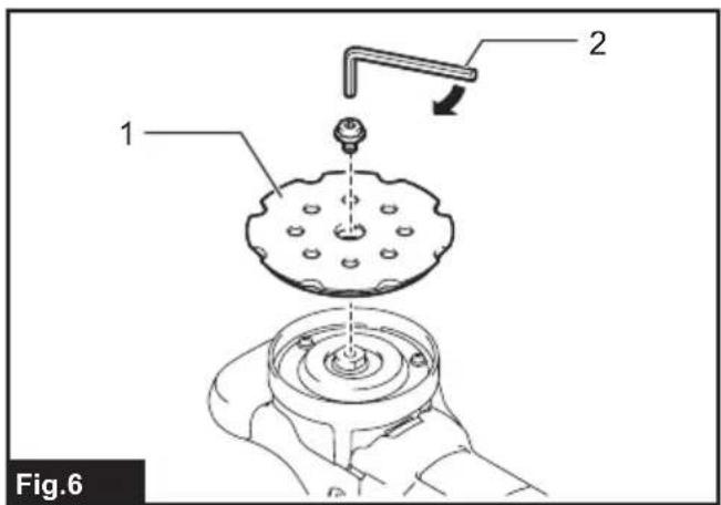
▶ Fig.6: 1. Backing pad 2. Hex wrench
Put the backing pad on the shaft then turn the bolt clockwise with a hex wrench.
⚠️CAUTION: Make sure that the backing pad is secured properly. Loose attachment will run out of balance and cause a excessive vibration which may cause loss of control.
Installing side grip
Optional accessory
▶ Fig.7: 1. Cap 2. Side grip
Remove the cap and screw the side grip on the tool securely.
The side grip can be installed on either side of the tool.
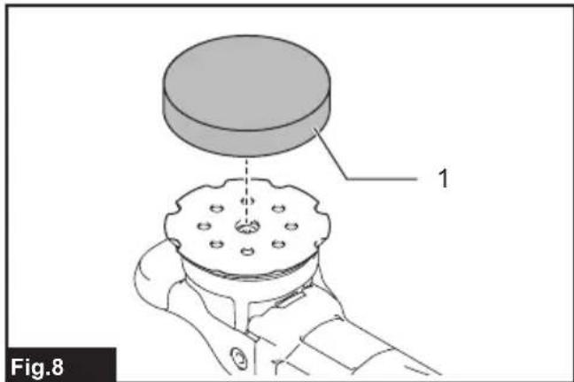
Installing or removing pad
Optional accessory
CAUTION: Only use hook-and-loop system pads for polishing.
▶ Fig.8: 1. Pad
To install the pad, first remove all dirt and foreign matter from the hook-and-loop system of the pad and the backing pad. Attach the pad to the backing pad so that their edges are aligned.
To remove the pad from the backing pad, just pull up from its edge.
⚠️ CAUTION: Make sure that the pad and backing pad are aligned and securely attached.
Otherwise the pad will cause a excessive vibration which may cause loss of control or the pad may be thrown out from the tool.
OPERATION
⚠️ CAUTION: Only use Makita genuine pads for polishing.
CAUTION: Make sure the work material is secured and stable. Falling object may cause personal injury.
⚠️ CAUTION: Hold the tool firmly with one hand on the switch handle and the other hand on the front grip (or side handle) when performing the tool.
CAUTION: Do not run the tool at high load over an extended time period. It may result in tool malfunction which causes electric shock, fire and/or serious injury.
⚠️ CAUTION: Be careful not to touch the rotating part.
NOTICE: Never force the tool. Excessive pressure may lead to decreased polishing efficiency, damaged pad, or shorten tool life.
NOTICE: Continuous operation at high speed may damage work surface.
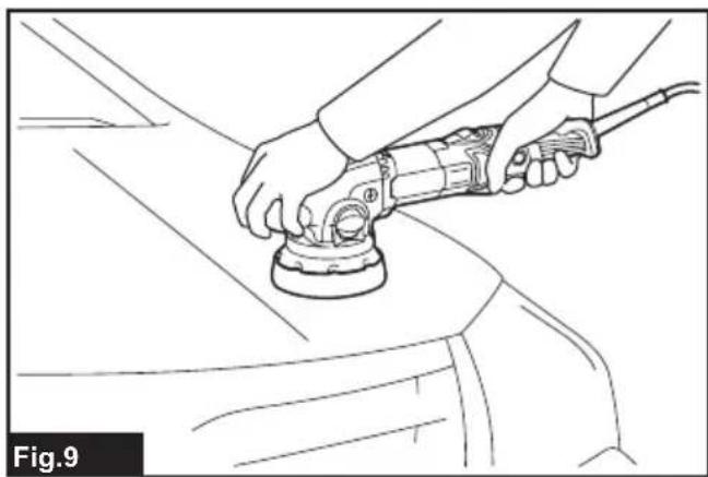
Polishing operation
▶ Fig.9
- Surface treatment (Random orbit with forced rotation mode)
Use a wool pad for rough finishing then use a sponge pad for fine finishing.
- Applying wax (Random orbit mode)
Use a sponge pad. Apply wax to the sponge pad or work surface. Run the tool at low speed to smooth out wax.
⚠️CAUTION: Do not apply excessive wax or polishing agent. It will generate more dust and may cause eye or respiratory diseases.
NOTE: First, perform a test waxing on an inconspicuous portion of the work surface. Make sure that the tool will not scratch the surface or result in uneven waxing before.
- Removing wax (Random orbit mode)
Use another sponge pad. Run the tool to remove wax.
- Polishing (Random orbit mode)
Apply a felt pad gently to the work surface.
MAINTENANCE
⚠️CAUTION: Always be sure that the tool is switched off and unplugged before attempting to perform inspection or maintenance.
NOTICE: Never use gasoline, benzine, thinner, alcohol or the like. Discoloration, deformation or cracks may result.
Cleaning dust covers
▶ Fig.10: 1. Dust cover
Regularly clean the dust covers on the inhalation vents for smooth air circulation. Remove the dust covers and clean the mesh.
To maintain product SAFETY and RELIABILITY, repairs, carbon brush inspection and replacement, any other maintenance or adjustment should be performed by Makita Authorized or Factory Service Centers, always using Makita replacement parts.
OPTIONAL ACCESSORIES
CAUTION: These accessories or attachments are recommended for use with your Makita tool specified in this manual. The use of any other accessories or attachments might present a risk of injury to persons. Only use accessory or attachment for its stated purpose.
If you need any assistance for more details regarding these accessories, ask your local Makita Service Center.
- Side grip
- Backing pad
- Wool pad
- Sponge pad
- Felt pad
NOTE: Some items in the list may be included in the tool package as standard accessories. They may differ from country to country.
SPÉCIFICATIONS
▶ Fig.6: 1. Plateau de support 2. Clé hexagonale
▶ Fig.10: 1. Pare-poussière
VEILIGHEIDSWAAR- SCHUWINGEN
OPTIONELE ACCESSOIRES
3-11-8, Sumiyoshi-cho,
Anjo, Aichi 446-8502 Japan