PV001G - Polisher MAKITA - Free user manual and instructions
Find the device manual for free PV001G MAKITA in PDF.

| Product Type | Cordless Polisher (battery) |
| Rated Voltage | 36 V - 40 V max (DC) |
| No Load Speed | 600 - 2,200 rpm (variable) |
| Pad Diameter | 180 mm (sheepskin) |
| Shaft Thread | M14 (Europe) / 15.88 mm (5/8"), M16 or M14 (other countries) |
| Overall Length (with BL4040 battery) | 531 mm |
| Net Weight | 3.0 - 4.4 kg (depending on battery) |
| Sound Pressure Level (LpA) | 80 dB(A) (uncertainty 3 dB(A)) |
| Vibration (polishing) | ≤ 2.5 m/s² (uncertainty 1.5 m/s²) |
| Compatible Batteries | BL4020, BL4025*, BL4040*, BL4050F*, BL4080F (*recommended) |
| Compatible Chargers | DC40RA, DC40RB, DC40RC |
| Electronic Functions | Constant speed control, soft start, protection against overload, overheating and deep discharge |
| Protection System | Tool/Battery Protection (automatic shut-off) |
| Supplied Accessories | Loop handle, side handle, hex wrench, lock nut wrench, sleeve 18 |
| Available Options | Foam pad, sheepskin pad, rubber cushion, lock nut 48 |
| Maintenance | Regularly clean the dust guards; use only genuine Makita parts |
| Safety | Wear safety glasses, hearing protection; maintain a firm two-handed grip |
| Standards | CE Directive 2006/42/EC, EN 62841-1, EN IEC 62841-2-3 |
| Warranty | Valid on condition of using genuine Makita batteries and chargers |
Frequently Asked Questions - PV001G MAKITA
User questions about PV001G MAKITA
0 question about this device. Answer the ones you know or ask your own.
Ask a new question about this device
Download the instructions for your Polisher in PDF format for free! Find your manual PV001G - MAKITA and take your electronic device back in hand. On this page are published all the documents necessary for the use of your device. PV001G by MAKITA.
USER MANUAL PV001G MAKITA
natural_image
Technical line drawing of a mechanical assembly with no visible text or symbols
natural_image
Technical line drawing of a mechanical device with a labeled component (1) and an arrow indicating a downward motion or force, no text or symbols present.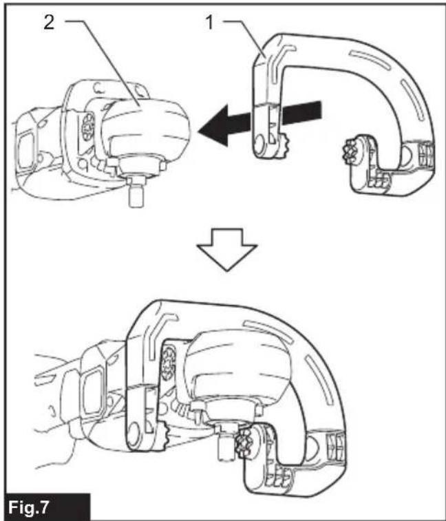
natural_image
Technical line drawing of a mechanical tool interacting with a textured surface, showing a 15° angle measurement (no text or symbols present)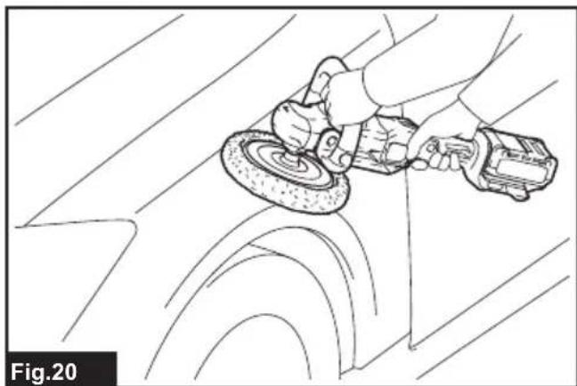
natural_image
Line drawing of a person using a power tool on a car wheel (no text or symbols)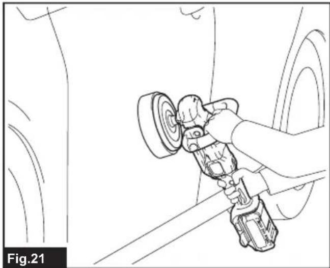
natural_image
Line drawing of a person using a power tool to clean or adjust equipment near a vehicle (no text or symbols)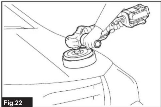
natural_image
Line drawing of a hand using a power tool to lift a car wheel (no text or symbols)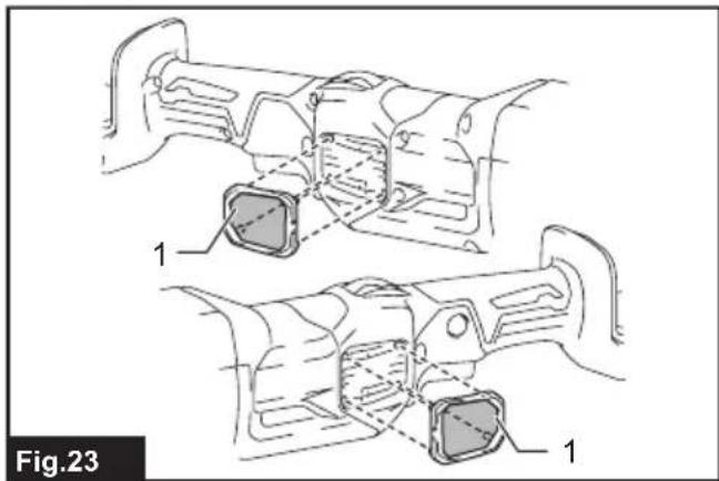
natural_image
Technical line drawing of a mechanical component with two views labeled 1, showing internal structure and assembly (no text or symbols beyond labels)SPECIFICATIONS
| Model: PV001G | ||
| Maximum capacities Wool pad 180 mm | ||
| Spindle thread European countries | Wool bonnet 180 mm | |
| Countries other than Europe (country specific) | 15.88 mm (5/8") / M16 / M14 | |
| Rated speed (n) / No load speed (n) 2,200 min | -1 | |
| Overall length (with battery cartridge BL4040) 531 mm | ||
| Rated voltage D.C. 36 V - 40 V max | ||
| Net weight 3.0 - 4.4 kg | ||
• Due to our continuing program of research and development, the specifications herein are subject to change without notice.
- Specifications and battery cartridge may differ from country to country.
- The weight may differ depending on the attachment(s), including the battery cartridge. The lightest and heaviest combinations, according to EPTA-Procedure 01/2014, are shown in the table.
Applicable battery cartridge and charger
| Battery cartridge BL4020 / BL4025* / BL4040* / BL4050F* / BL4080F | *: Recommended battery |
| Charger | DC40RA / DC40RB / DC40RC |
• Some of the battery cartridges and chargers listed above may not be available depending on your region of residence.

WARNING: Only use the battery cartridges and chargers listed above. Use of any other battery cartridges and chargers may cause injury and/or fire.
Symbols
The followings show the symbols which may be used for the equipment. Be sure that you understand their meaning before use.

Read instruction manual.


Wear safety glasses.
Maintain a firm grip with both hands on the power tool.

Ni-MH Li-ion
Only for EU countries
Due to the presence of hazardous components in the equipment, waste electrical and electronic equipment, accumulators and batteries may have a negative impact on the environment and human health. Do not dispose of electrical and electronic appliances or batteries with household waste!
In accordance with the European Directive on waste electrical and electronic equipment and on accumulators and batteries and waste accumulators and batteries, as well as their adaptation to national law, waste electrical equipment, batteries and accumulators should be stored separately and delivered to a separate collection point for municipal waste, operating in accordance with the regulations on environmental protection.
This is indicated by the symbol of the crossed-out wheeled bin placed on the equipment.
Intended use
The tool is intended for polishing.
Noise
The typical A-weighted noise level determined according to EN62841-2-3:
Sound pressure level (L _pA ) : 80 dB(A)
Uncertainty (K) : 3 dB(A)
The noise level under working may exceed 80 dB (A).
NOTE: The declared noise emission value(s) has been measured in accordance with a standard test method and may be used for comparing one tool with another.
NOTE: The declared noise emission value(s) may also be used in a preliminary assessment of exposure.
WARNING: Wear ear protection.
WARNING: The noise emission during actual use of the power tool can differ from the declared value(s) depending on the ways in which the tool is used especially what kind of workpiece is processed.
⚠ WARNING: Be sure to identify safety measures to protect the operator that are based on an estimation of exposure in the actual conditions of use (taking account of all parts of the operating cycle such as the times when the tool is switched off and when it is running idle in addition to the trigger time).
Vibration
The vibration total value (tri-axial vector sum) determined according to EN62841-2-3:
Work mode: polishing
Vibration emission (ah, P): 2.5 m/s ^2 or less
Uncertainty (K) : 1.5 m/s²
NOTE: The declared vibration total value(s) has been measured in accordance with a standard test method and may be used for comparing one tool with another.
NOTE: The declared vibration total value(s) may also be used in a preliminary assessment of exposure.
⚠ WARNING: The vibration emission during actual use of the power tool can differ from the declared value(s) depending on the ways in which the tool is used especially what kind of workpiece is processed.
⚠ WARNING: Be sure to identify safety measures to protect the operator that are based on an estimation of exposure in the actual conditions of use (taking account of all parts of the operating cycle such as the times when the tool is switched off and when it is running idle in addition to the trigger time).
EC Declaration of Conformity
For European countries only
The EC declaration of conformity is included as Annex A to this instruction manual.
SAFETY WARNINGS
General power tool safety warnings
WARNING: Read all safety warnings, instructions, illustrations and specifications provided with this power tool. Failure to follow all instructions listed below may result in electric shock, fire and/or serious injury.
Save all warnings and instructions for future reference.
The term "power tool" in the warnings refers to your mains-operated (corded) power tool or battery-operated (cordless) power tool.
Cordless polisher safety warnings
Safety Warnings for Polishing Operations:
-
This power tool is intended to function as a polisher. Read all safety warnings, instructions, illustrations and specifications provided with this power tool. Failure to follow all instructions listed below may result in electric shock, fire and/or serious injury.
-
Operations such as grinding, sanding, wire brushing, hole cutting or cutting-off are not to be performed with this power tool. Operations for which the power tool was not designed may create a hazard and cause personal injury.
-
Do not convert this power tool to operate in a way which is not specifically designed and specified by the tool manufacturer. Such a conversion may result in a loss of control and cause serious personal injury.
-
Do not use accessories which are not specifically designed and specified by the tool manufacturer. Just because the accessory can be attached to your power tool, it does not assure safe operation.
-
The rated speed of the accessory must be at least equal to the maximum speed marked on the power tool. Accessories running faster than their rated speed can break and fly apart.
-
The outside diameter and the thickness of your accessory must be within the capacity rating of your power tool. Incorrectly sized accessories cannot be adequately guarded or controlled.
-
The dimensions of the accessory mounting must fit the dimensions of the mounting hardware of the power tool. Accessories that do not match the mounting hardware of the power tool will run out of balance, vibrate excessively and may cause loss of control.
-
Do not use a damaged accessory. Before each use inspect the accessory such as abrasive wheels for chips and cracks, backing pad for cracks, tear or excess wear, wire brush for loose or cracked wires. If power tool or accessory is dropped, inspect for damage or install an undamaged accessory. After inspecting and installing an accessory, position yourself and bystanders away from the plane of the rotating accessory and run the power tool at maximum no-load speed for one minute. Damaged accessories will normally break apart during this test time.
-
Wear personal protective equipment.
Depending on application, use face shield, safety goggles or safety glasses. As appropriate, wear dust mask, hearing protectors, gloves and workshop apron capable of stopping small abrasive or workpiece fragments. The eye protection must be capable of stopping flying debris generated by various applications. The dust mask or respirator must be capable of filtrating particles generated by the particular application. Prolonged exposure to high intensity noise may cause hearing loss.
- Keep bystanders a safe distance away from work area. Anyone entering the work area must wear personal protective equipment.
Fragments of workpiece or of a broken accessory may fly away and cause injury beyond immediate area of operation.
-
Never lay the power tool down until the accessory has come to a complete stop. The spinning accessory may grab the surface and pull the power tool out of your control.
-
Do not run the power tool while carrying it at your side. Accidental contact with the spinning accessory could snag your clothing, pulling the accessory into your body.
-
Regularly clean the power tool's air vents. The motor's fan will draw the dust inside the housing and excessive accumulation of powdered metal may cause electrical hazards.
-
Do not operate the power tool near flammable materials. Sparks could ignite these materials.
-
Do not use accessories that require liquid coolants. Using water or other liquid coolants may result in electrocution or shock.
-
Do not allow any loose portion of the polishing bonnet or its attachment strings to spin freely. Tuck away or trim any loose attachment strings. Loose and spinning attachment strings can entangle your fingers or snag on the workpiece.
Kickback and Related Warnings
Kickback is a sudden reaction to a pinched or snagged rotating wheel, backing pad, brush or any other accessory. Pinching or snagging causes rapid stalling of the rotating accessory which in turn causes the uncontrolled power tool to be forced in the direction opposite of the accessory's rotation at the point of the binding.
For example, if an abrasive wheel is snagged or pinched by the workpiece, the edge of the wheel that is entering into the pinch point can dig into the surface of the material causing the wheel to climb out or kick out. The wheel may either jump toward or away from the operator, depending on direction of the wheel's movement at the point of pinching. Abrasive wheels may also break under these conditions.
Kickback is the result of power tool misuse and/or incorrect operating procedures or conditions and can be avoided by taking proper precautions as given below.
-
Maintain a firm grip with both hands on the power tool and position your body and arms to allow you to resist kickback forces. Always use auxiliary handle, if provided, for maximum control over kickback or torque reaction during start-up. The operator can control torque reactions or kickback forces, if proper precautions are taken.
-
Never place your hand near the rotating accessory. Accessory may kickback over your hand.
-
Do not position your body in the area where power tool will move if kickback occurs. Kickback will propel the tool in direction opposite to the wheel's movement at the point of snagging.
-
Use special care when working corners, sharp edges, etc. Avoid bouncing and snagging the accessory. Corners, sharp edges or bouncing have a tendency to snag the rotating accessory and cause loss of control or kickback.
-
Do not attach a saw chain woodcarving blade, segmented diamond wheel with a peripheral gap greater than 10 mm or toothed saw blade. Such blades create frequent kickback and loss of control.
Additional Safety Warnings:
-
Be careful not to damage the spindle, the flange (especially the installing surface) or the lock nut. Damage to these parts could result in wheel breakage.
-
Make sure the wheel is not contacting the workpiece before the switch is turned on.
-
Before using the tool on an actual workpiece, let it run for a while. Watch for vibration or wobbling that could indicate poor installation or a poorly balanced wheel.
-
Use the specified surface of the wheel to perform polishing.
-
Do not leave the tool running. Operate the tool only when hand-held.
-
Do not touch the workpiece immediately after operation; it may be extremely hot and could burn your skin.
-
Do not touch accessories immediately after operation; it may be extremely hot and could burn your skin.
-
Observe the instructions of the manufacturer for correct mounting and use of wheels. Handle and store wheels with care.
-
For tools intended to be fitted with threaded hole wheel, ensure that the thread in the wheel is long enough to accept the spindle length.
-
Check that the workpiece is properly supported.
-
Pay attention that the wheel continues to rotate after the tool is switched off.
-
Do not use the tool on any materials containing asbestos.
-
Do not use cloth work gloves during operation. Fibers from cloth gloves may enter the tool, which causes tool breakage.
SAVE THESE INSTRUCTIONS.
WARNING: DO NOT let comfort or familiarity with product (gained from repeated use) replace strict adherence to safety rules for the subject product. MISUSE or failure to follow the safety rules stated in this instruction manual may cause serious personal injury.
Important safety instructions for battery cartridge
- Before using battery cartridge, read all instructions and cautionary markings on (1) battery charger, (2) battery, and (3) product using battery.
- Do not disassemble or tamper with the battery cartridge. It may result in a fire, excessive heat, or explosion.
- If operating time has become excessively shorter, stop operating immediately. It may result in a risk of overheating, possible burns and even an explosion.
-
If electrolyte gets into your eyes, rinse them out with clear water and seek medical attention right away. It may result in loss of your eyesight.
-
Do not short the battery cartridge:
(1) Do not touch the terminals with any conductive material.
(2) Avoid storing battery cartridge in a container with other metal objects such as nails, coins, etc.
(3) Do not expose battery cartridge to water or rain.
A battery short can cause a large current flow, overheating, possible burns and even a breakdown.
-
Do not store and use the tool and battery cartridge in locations where the temperature may reach or exceed 50 °C (122 °F).
-
Do not incinerate the battery cartridge even if it is severely damaged or is completely worn out. The battery cartridge can explode in a fire.
-
Do not nail, cut, crush, throw, drop the battery cartridge, or hit against a hard object to the battery cartridge. Such conduct may result in a fire, excessive heat, or explosion.
-
Do not use a damaged battery.
-
The contained lithium-ion batteries are subject to the Dangerous Goods Legislation requirements.
For commercial transports e.g. by third parties, forwarding agents, special requirement on packaging and labeling must be observed.
For preparation of the item being shipped, consulting an expert for hazardous material is required.
Please also observe possibly more detailed national regulations.
Tape or mask off open contacts and pack up the battery in such a manner that it cannot move around in the packaging. -
When disposing the battery cartridge, remove it from the tool and dispose of it in a safe place. Follow your local regulations relating to disposal of battery.
-
Use the batteries only with the products specified by Makita. Installing the batteries to non-compliant products may result in a fire, excessive heat, explosion, or leak of electrolyte.
-
If the tool is not used for a long period of time, the battery must be removed from the tool.
- During and after use, the battery cartridge may take on heat which can cause burns or low temperature burns. Pay attention to the handling of hot battery cartridges.
- Do not touch the terminal of the tool immediately after use as it may get hot enough to cause burns.
- Do not allow chips, dust, or soil stuck into the terminals, holes, and grooves of the battery cartridge. It may cause heating, catching fire, burst and malfunction of the tool or battery cartridge, resulting in burns or personal injury.
-
Unless the tool supports the use near high-voltage electrical power lines, do not use the battery cartridge near a high-voltage electrical power lines. It may result in a malfunction or breakdown of the tool or battery cartridge.
-
Keep the battery away from children.
SAVE THESE INSTRUCTIONS.
CAUTION: Only use genuine Makita batteries. Use of non-genuine Makita batteries, or batteries that have been altered, may result in the battery bursting causing fires, personal injury and damage. It will also void the Makita warranty for the Makita tool and charger.
Tips for maintaining maximum battery life
- Charge the battery cartridge before completely discharged. Always stop tool operation and charge the battery cartridge when you notice less tool power.
- Never recharge a fully charged battery cartridge. Overcharging shortens the battery service life.
- Charge the battery cartridge with room temperature at 10 °C - 40 °C (50 °F - 104 °F). Let a hot battery cartridge cool down before charging it.
- When not using the battery cartridge, remove it from the tool or the charger.
- Charge the battery cartridge if you do not use it for a long period (more than six months).
FUNCTIONAL DESCRIPTION
⚠️CAUTION: Always be sure that the tool is switched off and the battery cartridge is removed before adjusting or checking function on the tool.
Installing or removing battery cartridge
⚠️CAUTION: Always switch off the tool before installing or removing of the battery cartridge.
⚠️CAUTION: Hold the tool and the battery cartridge firmly when installing or removing battery cartridge. Failure to hold the tool and the battery cartridge firmly may cause them to slip off your hands and result in damage to the tool and battery cartridge and a personal injury.
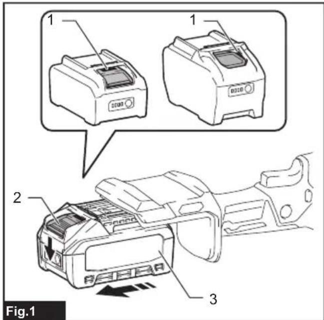
▶ Fig.1: 1. Red indicator 2. Button 3. Battery cartridge
To remove the battery cartridge, slide it from the tool while sliding the button on the front of the cartridge.
To install the battery cartridge, align the tongue on the battery cartridge with the groove in the housing and slip it into place. Insert it all the way until it locks in place with a little click. If you can see the red indicator as shown in the figure, it is not locked completely.
⚠CAUTION: Always install the battery cartridge fully until the red indicator cannot be seen. If not, it may accidentally fall out of the tool, causing injury to you or someone around you.
⚠️CAUTION: Do not install the battery cartridge forcibly. If the cartridge does not slide in easily, it is not being inserted correctly.
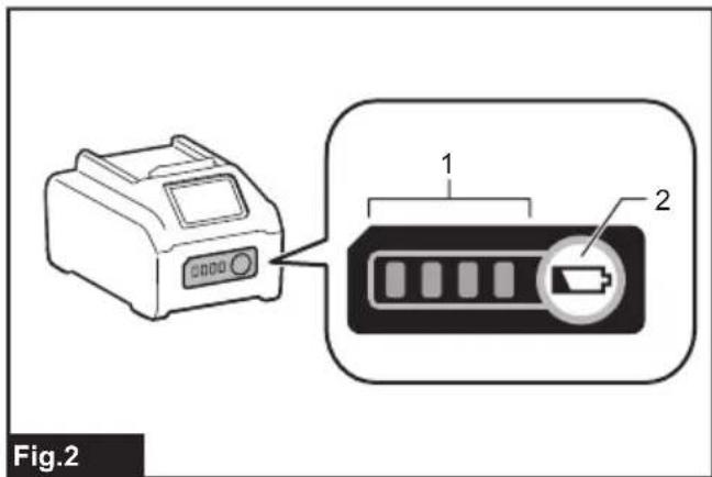
Indicating the remaining battery capacity
Press the check button on the battery cartridge to indicate the remaining battery capacity. The indicator lamps light up for a few seconds.
▶ Fig.2: 1. Indicator lamps 2. Check button
| Indicator lamps Remaining | capacity | ||
| Lighted Off | Blinking | ||
| 75% to 100% | |||
| 50% to 75% | |||
| 25% to 50% | |||
| 0% to 25% | |||
| Charge the battery. | |||
| The battery may have malfunctioned. | |||
NOTE: Depending on the conditions of use and the ambient temperature, the indication may differ slightly from the actual capacity.
NOTE: The first (far left) indicator lamp will blink when the battery protection system works.
Tool / battery protection system
The tool is equipped with a tool/battery protection system. This system automatically cuts off power to the motor to extend tool and battery life. The tool will automatically stop during operation if the tool or battery is placed under one of the following conditions:
Overload protection
When the tool/battery is operated in a manner that causes it to draw an abnormally high current, the tool automatically stops. In this situation, turn the tool off and stop the application that caused the tool to become overloaded. Then turn the tool on to restart.
Overheat protection
When the tool/battery is overheated, the tool stops automatically. In this situation, let the tool/battery cool before turning the tool on again.
Overdischarge protection
When the battery capacity is not enough, the tool stops automatically. In this case, remove the battery from the tool and charge the battery.
Protections against other causes
Protection system is also designed for other causes that could damage the tool and allows the tool to stop automatically. Take all the following steps to clear the causes, when the tool has been brought to a temporary halt or stop in operation.
- Turn the tool off, and then turn it on again to restart.
- Charge the battery(ies) or replace it/them with recharged battery(ies).
- Let the tool and battery(ies) cool down.
If no improvement can be found by restoring protection system, then contact your local Makita Service Center.
Switch action
CAUTION: Before installing the battery cartridge into the tool, always check to see that the switch trigger actuates properly and returns to the "OFF" position when released.
CAUTION: Switch can be locked in "ON" position for ease of operator comfort during extended use. Apply caution when locking tool in "ON" position and maintain firm grasp on tool.
CAUTION: Do not install the battery cartridge with the lock button engaged.
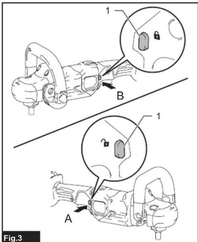
CAUTION: When not operating the tool, depress the trigger-lock button from side to lock the switch trigger in the OFF position.
▶ Fig.3: 1. Trigger-lock button
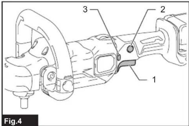
▶ Fig.4: 1. Switch trigger 2. Lock button 3. Trigger-lock button
To prevent the switch trigger from accidentally pulled, the trigger-lock button is provided. To start the tool, depress the trigger-lock button from A (inside and pull the switch trigger. Tool speed is increased by increasing pressure on the switch trigger. Release the switch trigger to stop. After use, depress the trigger-lock button from B (inside.
For continuous operation, depress the lock button while pulling the switch trigger, and then release the switch trigger. To stop the tool, pull the switch trigger fully, then release it.
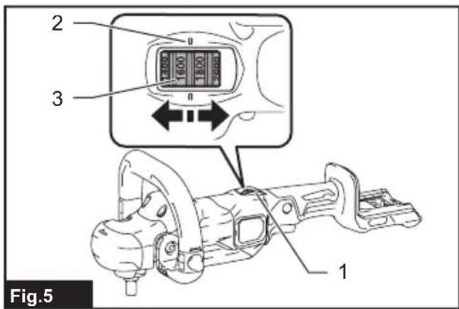
Speed adjusting dial
The rotating speed can be changed by using the speed adjusting dial on top of the switch handle. Turn the speed adjusting dial to align the pointers with your desired rotating speed indicated on the speed scale. The rotating speed can be adjusted from 600 (RPM) to 2,200 (RPM), and a target speed can be obtained when the switch trigger is fully squeezed.
▶ Fig.5: 1. Speed adjusting dial 2. Pointer 3. Speed scale
NOTICE: If the tool is operated continuously at low speeds for a long time, the motor will get overloaded, resulting in tool malfunction.
NOTICE: The speed adjusting dial turns between 600 and 2,200 on the speed scale. Avoid turning the dial back and forwards further as it may cause damage to the tool.
NOTE: Be sure to read numbers on the scale as an indicator since the actual speed may fluctuate slightly.
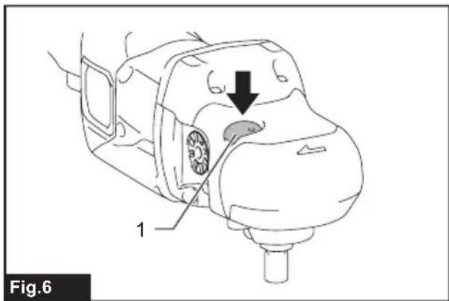
Shaft lock
Press the shaft lock to prevent spindle rotation when installing and removing accessories.
▶ Fig.6: 1. Shaft lock
NOTICE: Never actuate the shaft lock while the spindle is moving. The tool may be damaged.
Accidental restart preventive function
If you install the battery cartridge while pulling the switch trigger or locking the switch trigger, the tool does not start. To start the tool, release the switch trigger, and then pull the switch trigger.
Electronic function
The tool is equipped with the following electronic functions for easy operation.
Constant speed control
Possible to get fine finish, because the rotating speed is kept constant even under the loaded condition.
Soft start feature
The soft-start function minimizes start-up shock, and makes the tool start smoothly.
ASSEMBLY
CAUTION: Always be sure that the tool is switched off and the battery cartridge is removed before carrying out any work on the tool.
Installing loop handle
CAUTION: Be sure to hold the tool firmly with both hands, positioning one hand on the switch handle and the other on the loop handle, side grip or tool head.
CAUTION: Make sure that the loop handle is installed securely before operation.
- Place the loop handle over the tool head by passing the tool head through the loop of the handle.
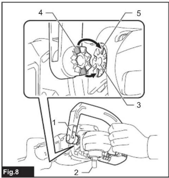
▶ Fig.7: 1. Loop handle 2. Tool head - Attach the straight end of the loop handle over the mounting hole on side of the tool head, fitting the guide ridges on the handle end well into the guide grooves around the mounting hole.
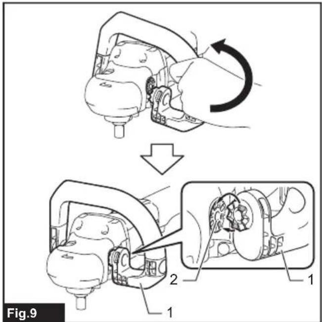
▶ Fig.8: 1. Straight end of loop handle 2. Spindle 3. Mounting hole 4. Guide ridge 5. Guide groove - Hold the loop handle and pull the loop end over the mounting hole on the other side of the tool head, refining angles to engage the handle position.
- Install and tighten the hex bolts into the mounting holes on both sides of the tool head to secure the loop handle in place.
▶ Fig.9: 1. Loop end of loop handle 2. Mounting hole
NOTE: The loop handle has an asymmetric shape that can be applied for left or right hand, making it more comfortable for you to grip and easy for polishing.
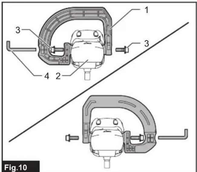
▶ Fig.10: 1. Loop handle 2. Tool head 3. Hex bolt 4. Hex wrench
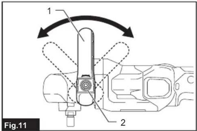
NOTE: The loop handle can be laid down back and forwards according to your preferred position. Loosen the hex bolts, move the handle to your desired angle and then refasten the bolts to lock the angle.
▶ Fig.11: 1. Loop handle 2. Hex bolt
Installing side grip
CAUTION: Be sure to hold the tool firmly with both hands, positioning one hand on the switch handle and the other on the loop handle, side grip or tool head.
⚠️ CAUTION: Make sure that the side grip is installed securely before operation.
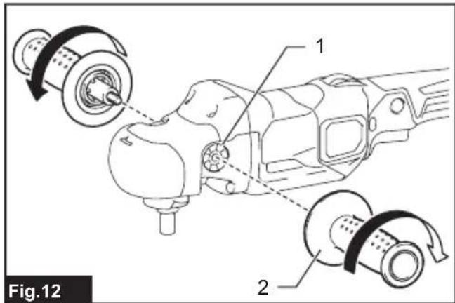
Screw the side grip tightly into the mounting hole on either side of the tool head.
▶ Fig.12: 1. Mounting hole 2. Side grip
Installing and removing wool pad
Optional accessory
⚠️CAUTION: Make sure that the backing pad is secured properly. Loose attachment will run out of balance and cause an excessive vibration which may cause loss of control.
⚠️CAUTION: Make sure that the wool pad and backing pad are aligned and securely attached. Otherwise the wool pad will cause an excessive vibration which may cause loss of control or the wool pad may be thrown out from the tool.
⚠️CAUTION: Only use the hook-and-loop system wool pads for polishing.
NOTICE: Never actuate the shaft lock when the spindle is moving. The tool may be damaged.
NOTICE: Regularly clean accessories and spindle to remove dust and debris. Wipe the components clean with a cloth dampened in soapy water if necessary.
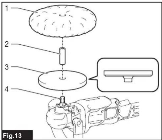
▶ Fig.13: 1. Wool pad 2. Sleeve 18 3. Backing pad 4. Spindle
Installing wool pad
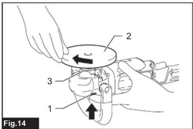
- Press in the shaft lock to prevent spindle rotation, and thread the backing pad into the spindle.
- Hand tighten the backing pad securely.
▶ Fig.14: 1. Shaft lock 2. Backing pad 3. Spindle
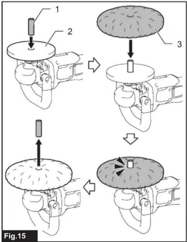
- Insert the sleeve 18 into the center hole of the backing pad.
- Install the wool pad over the backing pad, passing the sleeve 18 through the center hole of the wool pad. Use the sleeve 18 as a positioning guide to align the wool pad accurately along the backing pad.
- Pull the sleeve 18 out of the center hole of the backing pad.
▶ Fig.15: 1. Sleeve 18 2. Backing pad 3. Wool pad
Removing wool pad
- Gently peel the wool pad off the backing pad.
- Unscrew the backing pad while pressing in the shaft lock.
Installing and removing wool bonnet
Optional accessory
⚠️CAUTION: Make sure that the rubber pad is secured properly. Loose attachment will run out of balance and cause an excessive vibration which may cause loss of control.
NOTICE: Never actuate the shaft lock when the spindle is moving. The tool may be damaged.
NOTICE: Regularly clean accessories and spindle to remove dust and debris. Wipe the components clean with a cloth dampened in soapy water if necessary.
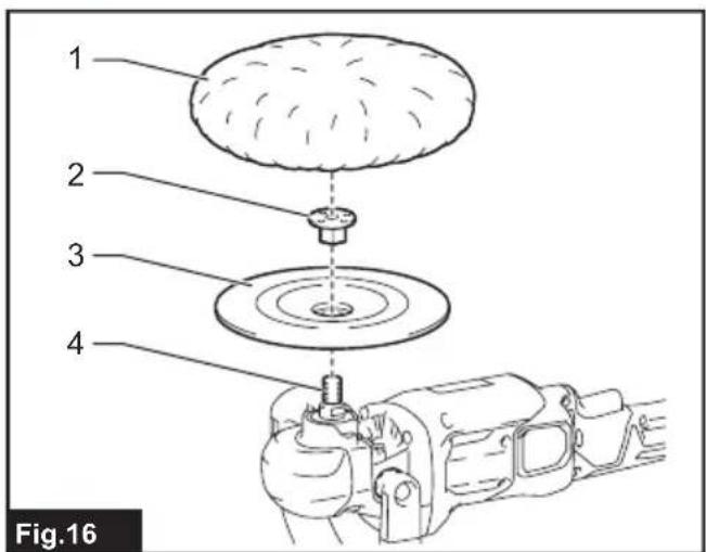
▶ Fig.16: 1. Wool bonnet 2. Lock nut 3. Rubber pad 4. Spindle
Installing wool bonnet
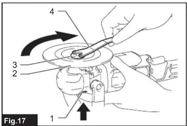
- Press in the shaft lock to prevent spindle rotation.
- Place the rubber pad over the spindle, passing the spindle thread through the center hole of the rubber pad.
- Install the lock nut onto the spindle, and then tighten it clockwise using the lock nut wrench to secure the rubber pad firmly in place.
▶ Fig.17: 1. Shaft lock 2. Rubber pad 3. Lock nut 4. Lock nut wrench
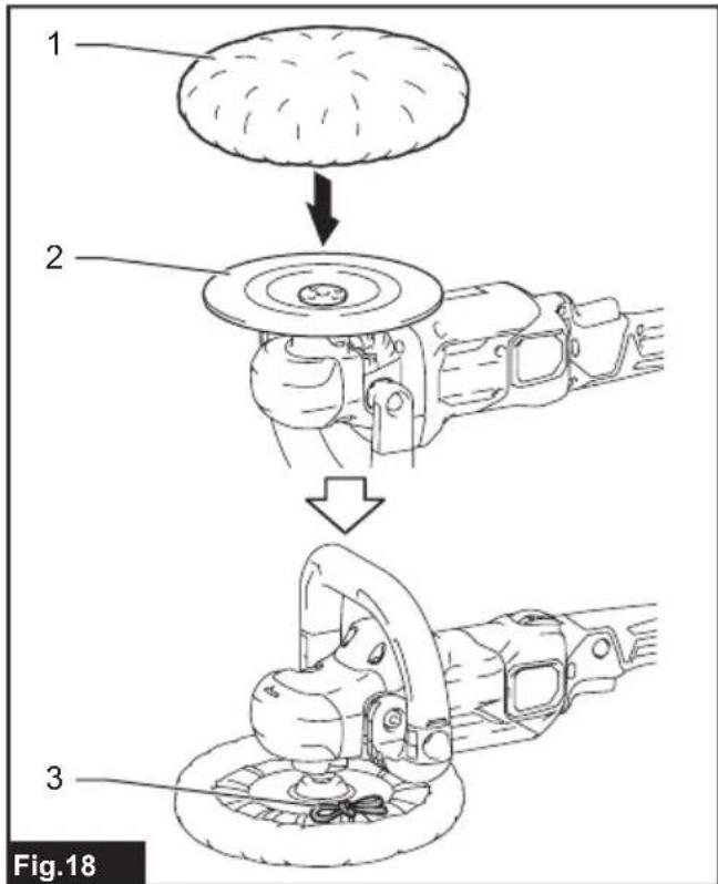
- Lay the wool bonnet down over the rubber pad and cover up completely.
- Turn the tool upside down. Pull the strings tight and tie a bow knot. Then tuck the knot and any loose strings between the wool bonnet and the rubber pad.
▶ Fig.18: 1. Wool bonnet 2. Rubber pad 3. Strings
Removing wool bonnet
- Untie the bow knot and gently remove the wool bonnet from the rubber pad.
- Loosen the lock nut counterclockwise with the lock nut wrench while pressing in the shaft lock. Pull the lock nut and rubber pad off the spindle.
OPERATION
CAUTION: Only use Makita genuine pads for polishing (optional accessories).
CAUTION: Be sure to hold the tool firmly with both hands, positioning one hand on the switch handle and the other on the loop handle, side grip or tool head.
⚠️ CAUTION: Make sure that the loop handle or side grip is installed securely before operation.
CAUTION: Make sure the work material is secured and stable. Falling object may cause personal injury.
CAUTION: Do not run the tool at high load over an extended time period. It may result in tool malfunction which causes electric shock, fire and/or serious injury.
⚠️ CAUTION: Be careful not to touch the rotating part.
NOTICE: Never force the tool. Excessive pressure may lead to decreased polishing efficiency, damaged pad, or shorten tool life.
NOTICE: Continuous operation at high speed may damage work surface.
Polishing basics
⚠️CAUTION: Always wear safety glasses or a face shield during operation.
NOTICE: It is recommended that you have a trial run over an inconspicuous spot to find an appropriate workload.
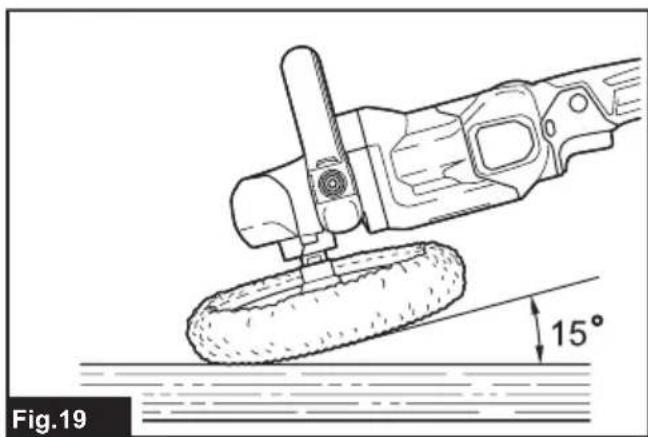
▶ Fig.19
- Make sure that the workpiece is properly supported and both hands are free to control the tool.
- Hold the tool firmly with one hand on the switch handle and the other hand on the loop handle, side grip or tool head.
- Turn the tool on, letting the polishing wheel reach full speed. Then carefully enter into operation moving the tool back and forth with steady pressure over the workpiece surface.
NOTE: Keep the wool pad/bonnet at an angle of about 15 degrees to the workpiece surface.
NOTE: Apply an even amount of gentle pressure over the polishing wheel. Excessive pressure will result in poor performance and premature wear to wool pad/bonnet.
- Having finished, switch the tool off and wait until the wheel has come to a complete stop before putting the tool down.
Polishing operations
Surface treatment
Use a wool pad for rough finishing, then use a sponge pad (optional accessory) for fine finishing.
▶ Fig.20
Applying wax
Apply wax to the sponge pad (optional accessory) or work surface. Run the tool at low speed to smooth out wax.
▶ Fig.21
⚠️CAUTION: Do not apply excessive wax or polishing agent. It will generate more dust and may cause eye or respiratory diseases.
NOTE: First, perform a test waxing on an inconspicuous portion of the work surface. Make sure that the tool will not scratch the surface, or it may result in uneven waxing.
Removing wax
Apply with a clean sponge pad (optional accessory). Run the tool to remove wax.
▶ Fig.22
MAINTENANCE
CAUTION: Always be sure that the tool is switched off and the battery cartridge is removed before attempting to perform inspection or maintenance.
NOTICE: Never use gasoline, benzine, thinner, alcohol or the like. Discoloration, deformation or cracks may result.
To maintain product SAFETY and RELIABILITY, repairs, any other maintenance or adjustment should be performed by Makita Authorized or Factory Service Centers, always using Makita replacement parts.
Cleaning dust covers
▶ Fig.23: 1. Dust cover
Regularly clean the dust covers on the inhalation vents for smooth air circulation. Remove the dust covers and clean the mesh.
OPTIONAL ACCESSORIES
CAUTION: These accessories or attachments are recommended for use with your Makita tool specified in this manual. The use of any other accessories or attachments might present a risk of injury to persons. Only use accessory or attachment for its stated purpose.
If you need any assistance for more details regarding these accessories, ask your local Makita Service Center.
- Lock nut 48
- Lock nut wrench 28
- Sponge pad (Hook & loop)
• Wool pad 180 (Hook & loop) - Wool bonnet 180
- Backing pad 165 (Hook & loop)
- Rubber pad 170
- Sleeve 18
- Side grip (auxiliary handle)
- Loop handle
- Makita genuine battery and charger
NOTE: Some items in the list may be included in the tool package as standard accessories. They may differ from country to country.
SPÉCIFICATIONS
▶ Fig.11: 1. Poignée arceau 2. Boulon hexagonal
▶ Fig.23: 1. Pare-poussière
⚠ WAARSCHUWING: Draag gehoorbescherming.
VEILIGHEIDSWAAR- SCHUWINGEN
▶ Fig.7: 1. Beugelhandgreep 2. Gereedschapskop
▶ Fig.11: 1. Beugelhandgreep 2. Inbusbout
OPTIONELE ACCESSOIRES
▶ Fig.11: 1. Mango circular 2. Perno hexagonal
3-11-8, Sumiyoshi-cho,
Anjo, Aichi 446-8502 Japan
ENGLISH
Annex A: EC Declaration of Conformity
e as t e manu at urers Makita Europe N.V., Business a ress Jan-Baptist Vinkstraat 2, 3070 Kortenberg, BELGIUM. ut ori e Hiroshi Tsujimura or t e o mpilation of the technical file and declare under our sole responsibility t at t e pro ut s esignation Cordless Designation of Type(s): PV001G. Fulfills all the relevant provisions of 2006/42/EC and also fulfills all the relevant provisions of the following EC/EU Directives: 2014/30/EU, 2011/65/EU and are manufactured in accordance with the following Harmonised Standards: EN 62841-1:2015, EN IEC 62841-2-3:2021+A11:2021, EN IEC 55014-1:2021, EN IEC 55014-2:2021, EN IEC 63000:2018.
lae o e laration Kortenberg, Belgium. Responsible person Hiroshi Tsujimura, Director - Makita Europe N.V. ate an signature on t e last page