PW5000C - Polisher MAKITA - Free user manual and instructions
Find the device manual for free PW5000C MAKITA in PDF.

| Product Type | Polisher |
| Brand | Makita |
| Model | PW5000C |
| Max. abrasive disc capacity | 125 mm |
| Shaft thread | M14 or 5/8" depending on country |
| Max. shaft length | 23 mm |
| No-load speed (n0) | 4,400 min⁻¹ |
| Variable speed | 2,000 to 4,400 min⁻¹ (5 positions) |
| Overall length | 313 mm |
| Net weight | 2.3 to 2.6 kg |
| Safety class | Double insulation (Class II) |
| Power supply | Single-phase, 110 V (via isolation transformer) or 230 V depending on country |
| Main functions | Natural stone polishing, soft start, electronic speed control, overload protection, shaft lock |
| Water supply | Yes, max pressure 7 bar, lever for opening/closing |
| Sound pressure level (Lpa) | 88 dB(A) |
| Sound power level (Lwa) | 96 dB(A) |
| Vibration (stone polishing) | 5.0 m/s² (uncertainty K=1.5 m/s²) |
| Maintenance | Clean ventilation openings regularly, use genuine Makita parts |
| Safety | Safety goggles, noise protection headset, two-handed use, personal protective equipment |
| Spare parts and repairability | Repairs by Makita authorized service center, accessories: side handle, abrasive disc, backing pad, dust guard |
| General information | Manual available in several languages, CE compliant, do not dispose with household waste |
Frequently Asked Questions - PW5000C MAKITA
User questions about PW5000C MAKITA
0 question about this device. Answer the ones you know or ask your own.
Ask a new question about this device
Download the instructions for your Polisher in PDF format for free! Find your manual PW5000C - MAKITA and take your electronic device back in hand. On this page are published all the documents necessary for the use of your device. PW5000C by MAKITA.
USER MANUAL PW5000C MAKITA
| Model: PW5000C PW5000CH | |||
| Max. capacity Abrasive disc 125 mm | |||
| Spindle thread M14 or 5/8" (country specific) | |||
| Max. spindle length 23 mm | |||
| No load speed (n0) / Rated speed (n) 4,400 min | -1 | ||
| Overall length 313 mm | |||
| Net weight 2.3 - 2.6 kg | |||
| Safety class | ☐/II | ||
- Due to our continuing program of research and development, the specifications herein are subject to change without notice.
- Specifications may differ from country to country.
- The weight may differ depending on the attachment(s). The lightest and heaviest combinations, according to EPTA-Procedure 01/2014, are shown in the table.
Symbols
The followings show the symbols which may be used for the equipment. Be sure that you understand their meaning before use.

Read instruction manual.

Wear safety glasses.

Always operate with two hands.

DOUBLE INSULATION

Only for EU countries
Due to the presence of hazardous components in the equipment, used electrical and electronic equipment may have a negative impact on the environment and human health.
Do not dispose of electrical and electronic appliances with household waste! In accordance with the European Directive on waste electrical and electronic equipment and its adaptation to national law, used electrical and electronic equipment should be collected separately and delivered to a separate collection point for municipal waste, operating in accordance with the environmental protection regulations.
This is indicated by the symbol of the crossed-out wheeled bin placed on the equipment.
Intended use
The tool is intended for surface work with natural stone.
Power supply
The tool should be connected only to a power supply of the same voltage as indicated on the nameplate, and can only be operated on single-phase AC supply. They are double-insulated and can, therefore, also be used from sockets without earth wire.
The typical A-weighted noise level determined according to EN62841-2-3:
Noise
| Model Sound pressure | level \( \left( {\mathrm{L}}_{\mathrm{{pA}}}\right) : \left( {\mathrm{{dB}}\left( \mathrm{A}\right) }\right) \) | Sound power level (LwA) : (dB(A)) | Uncertainty (K) : (dB(A)) |
| PW5000C 88 96 3 | |||
| PW5000CH | 88 96 3 |
NOTE: The declared noise emission value(s) has been measured in accordance with a standard test method and may be used for comparing one tool with another.
NOTE: The declared noise emission value(s) may also be used in a preliminary assessment of exposure.
WARNING: Wear ear protection.
WARNING: The noise emission during actual use of the power tool can differ from the declared value(s) depending on the ways in which the tool is used especially what kind of workpiece is processed.
WARNING: Be sure to identify safety measures to protect the operator that are based on an estimation of exposure in the actual conditions of use (taking account of all parts of the operating cycle such as the times when the tool is switched off and when it is running idle in addition to the trigger time).
Vibration
The vibration total value (tri-axial vector sum) determined according to EN62841-2-3:
Work mode: stone polishing
| Model | Vibration emission (a,1,P) : (m/s2) | Uncertainty (K) : (m/s2) |
| PW5000C 5.0 1.5 | ||
| PW5000CH 5.0 1.5 |
NOTE: The declared vibration total value(s) has been measured in accordance with a standard test method and may be used for comparing one tool with another.
NOTE: The declared vibration total value(s) may also be used in a preliminary assessment of exposure.
WARNING: The vibration emission during actual use of the power tool can differ from the declared value(s) depending on the ways in which the tool is used especially what kind of workpiece is processed.
WARNING: Be sure to identify safety measures to protect the operator that are based on an estimation of exposure in the actual conditions of use (taking account of all parts of the operating cycle such as the times when the tool is switched off and when it is running idle in addition to the trigger time).
WARNING: The declared vibration emission value is used for main applications of the power tool. However if the power tool is used for other applications, the vibration emission value may be different.
EC Declaration of Conformity
For European countries only
The EC declaration of conformity is included as Annex A to this instruction manual.
SAFETYWARNINGS
General power tool safety warnings
WARNING: Read all safety warnings, instructions, illustrations and specifications provided with this power tool. Failure to follow all instructions listed below may result in electric shock, fire and/or serious injury.
Save all warnings and instructions for future reference.
The term "power tool" in the warnings refers to your mains-operated (corded) power tool or battery-operated (cordless) power tool.
Stone polisher safety warnings
Safety warnings common for polishing operations:
-
This power tool is intended to function as a polisher. Read all safety warnings, instructions, illustrations and specifications provided with this power tool. Failure to follow all instructions listed below may result in electric shock, fire and/or serious injury.
-
Operations such as grinding, sanding, wire brushing, hole cutting or cutting-off are not to be performed with this power tool. Operations for which the power tool was not designed may create a hazard and cause personal injury.
- Do not convert this power tool to operate in a way which is not specifically designed and specified by the tool manufacturer. Such a conversion may result in a loss of control and cause serious personal injury.
- Do not use accessories which are not specifically designed and specified by the tool manufacturer. Just because the accessory can be attached to your power tool, it does not assure safe operation.
- The rated speed of the accessory must be at least equal to the maximum speed marked on the power tool. Accessories running faster than their rated speed can break and fly apart.
- The outside diameter and the thickness of your accessory must be within the capacity rating of your power tool. Incorrectly sized accessories cannot be adequately guarded or controlled.
- The dimensions of the accessory mounting must fit the dimensions of the mounting hardware of the power tool. Accessories that do not match the mounting hardware of the power tool will run out of balance, vibrate excessively and may cause loss of control.
-
Do not use a damaged accessory. Before each use inspect the accessory such as abrasive wheels for chips and cracks, backing pad for cracks, tear or excess wear, wire brush for loose or cracked wires. If power tool or accessory is dropped, inspect for damage or install an undamaged accessory. After inspecting and installing an accessory, position yourself and bystanders away from the plane of the rotating accessory and run the power tool at maximum no-load speed for one minute. Damaged accessories will normally break apart during this test time.
-
Wear personal protective equipment. Depending on application, use face shield, safety goggles or safety glasses. As appropriate, wear dust mask, hearing protectors, gloves and workshop apron capable of stopping small abrasive or workpiece fragments. The eye protection must be capable of stopping flying debris generated by various applications. The dust mask or respirator must be capable of filtrating particles generated by the particular application. Prolonged exposure to high intensity noise may cause hearing loss.
- Keep bystanders a safe distance away from work area. Anyone entering the work area must wear personal protective equipment. Fragments of workpiece or of a broken accessory may fly away and cause injury beyond immediate area of operation.
- Position the cord clear of the spinning accessory. If you lose control, the cord may be cut or snagged and your hand or arm may be pulled into the spinning accessory.
- Never lay the power tool down until the accessory has come to a complete stop. The spinning accessory may grab the surface and pull the power tool out of your control.
- Do not run the power tool while carrying it at your side. Accidental contact with the spinning accessory could snag your clothing, pulling the accessory into your body.
- Regularly clean the power tool's air vents. The motor's fan will draw the dust inside the housing and excessive accumulation of powdered metal may cause electrical hazards.
- Do not operate the power tool near flammable materials. Sparks could ignite these materials.
Kickback and related warnings:
Kickback is a sudden reaction to a pinched or snagged rotating wheel, backing pad, brush or any other accessory. Pinching or snagging causes rapid stalling of the rotating accessory which in turn causes the uncontrolled power tool to be forced in the direction opposite of the accessory's rotation at the point of the binding. For example, if an abrasive wheel is snagged or pinched by the workpiece, the edge of the wheel that is entering into the pinch point can dig into the surface of the material causing the wheel to climb out or kick out. The wheel may either jump toward or away from the operator, depending on direction of the wheel's movement at the point of pinching. Abrasive wheels may also break under these conditions. Kickback is the result of power tool misuse and/or incorrect operating procedures or conditions and can be avoided by taking proper precautions as given below.
- Maintain a firm grip with both hands on the power tool and position your body and arms to allow you to resist kickback forces. Always use auxiliary handle, if provided, for maximum control over kickback or torque reaction during start-up. The operator can control torque reactions or kickback forces, if proper precautions are taken.
-
Never place your hand near the rotating accessory. Accessory may kickback over your hand.
-
Do not position your body in the area where power tool will move if kickback occurs. Kickback will propel the tool in direction opposite to the wheel's movement at the point of snagging.
- Use special care when working corners, sharp edges, etc. Avoid bouncing and snagging the accessory. Corners, sharp edges or bouncing have a tendency to snag the rotating accessory and cause loss of control or kickback.
- Do not attach a saw chain woodcarving blade, segmented diamond wheel with a peripheral gap greater than 10mm or toothed saw blade. Such blades create frequent kickback and loss of control.
Safety warnings specific for polishing operations:
- Do not allow any loose portion of the polishing bonnet or its attachment strings to spin freely. Tuck away or trim any loose attachment strings. Loose and spinning attachment strings can entangle your fingers or snag on the workpiece.
Additional SafetyWarnings:
- Make sure the abrasive disc is not contacting the workpiece before the switch is turned on.
- Do not leave the tool running. Operate the tool only when hand-held.
- Observe the instructions of the manufacturer for correct mounting and use of accessories. Handle and store accessories with care.
- Check that the workpiece is properly supported.
- Pay attention that the wheel continues to rotate after the tool is switched off.
- Do not use the tool on any materials containing asbestos.
- Do not use excessively oversized abrasive disc. Follow manufacturers recommendations, when selecting abrasive disc. Larger abrasive disc extending beyond the pad presents a laceration hazard and may cause snagging, tearing of the disc or kickback.
SAVE THESE INSTRUCTIONS.
WARNING: DO NOT let comfort or familiarity with product (gained from repeated use) replace strict adherence to safety rules for the subject product. MISUSE or failure to follow the safety rules stated in this instruction manual may cause serious personal injury.
Important Notes about Mains Connection for 110 Volts, 50-60Hz
WARNING: Read and observe these precautions before using the tool. Non-observation of these precautions may lead to personal injuries and damage to the tool!
The tool was built according to the European Standards EN62841-1 (safety of hand-held, motor-driven power tools; here in particular section of power tools with water connection) and EN60309-2 (plugs, receptacles and couplings for industrial applications). When applying these standards, the earth contact position of the plug-in device may only be carried out in "12 o'clock position".
The tool has a plug-in device with a "12 o'clock" earth contact position.
However, since the European Standard EN60309-2 does not provide a differentiation regarding the supply voltage and this earth contact position, there is the possibility to confuse the connection to an isolating transformer with another output voltage (e.g. 230V ). When connecting the tool to an isolating transformer, make absolutely sure to use the correct output voltage (110V, 50 - 60Hz) .
This tool is designed exclusively for connection to an isolating transformer with an output voltage of 110V . Due to its use in wet conditions (water connection on the tool), this tool must never be connected to a power supply without an isolating transformer.
Damages caused by inappropriate tampering with the plug-in device are not subject to warranty or legal guarantee claims.
Contact your specialist supplier for an isolating transformer suitable for your tool.
FUNCTIONAL DESCRIPTION
CAUTION: Always be sure that the tool is switched off and unplugged before adjusting or checking function on the tool.
Shaft lock
WARNING: Never actuate the shaft lock when the spindle is moving. It may cause serious injury on the tool damage.
Press the shaft lock to prevent spindle rotation when installing or removing accessories.
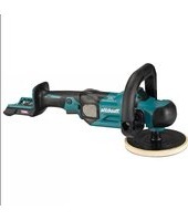
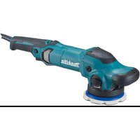
Fig.1: 1. Shaft lock
Switch action
CAUTION: Before plugging in the tool, always check to see that the slide switch actuates properly and returns to the "OFF" position when the rear end of the slide switch is depressed.
CAUTION: Switch can be locked in the "ON" position for ease of operator comfort during extended use. Apply caution when locking tool in the "ON" position and maintain firm grasp on tool.
To start the tool, press down the rear end of the slide switch and then slide it toward the "I (ON)" position. For continuous operation, press down the front end of the slide switch to lock it.
Fig.2: 1. Slide switch
To stop the tool, press down the rear end of the slide switch so that it returns to the "O (OFF)" position.
Fig.3: 1. Slide switch
Speed adjusting dial
The rotation speed of the tool can be changed by turning the speed adjusting dial. The table below shows the number on the dial and the corresponding rotation speed.
Fig.4: 1. Speed adjusting dial
| Number Speed | |
| 1 2,000 min | -1 |
| 2 2,500 min | -1 |
| 3 3,000 min | -1 |
| 4 3,500 min | -1 |
| 5 4,400 min | -1 |
NOTICE: If the tool is operated continuously at low speed for a long time, the motor will get overloaded, resulting in tool malfunction.
NOTICE: The speed adjusting dial can be turned only as far as 5 and back to 1. Do not force it past 5 or 1, or the speed adjusting function may no longer work.
Constant speed control
Possible to get fine finish, because the rotating speed is kept constantly even under the loaded condition.
Soft start feature
Soft start feature reduces starting reaction.
Overload protector
When the load on the tool exceeds admissible levels, power to the motor is reduced to protect the motor from overheating. When the load returns to admissible levels, the tool will operate as normal.
Opening or closing of water lever
To keep the lever on the tool for water flow open, turn it to the position A where the water passage will be ready. Return it to the position B to close.
Fig.5: 1. Lever 2. Open 3. Close
ASSEMBLY
CAUTION: Always be sure that the tool is switched off and unplugged before carrying out any work on the tool.
Installing side grip (handle)
CAUTION: Always be sure that the side grip is installed securely before operation.
Screw the side grip securely on the position of the tool as shown in the figure.
Fig.6
Installing or removing abrasive disc
- Remove all dirt or foreign matter from the pad.
- Screw the pad onto the spindle with pressing the shaft lock.
- Attach the disc to the pad so carefully that the edges of disc and pad overlap each other without protruding.
▶ Fig.7: 1. Abrasive disc 2. Pad 3. Spindle
To remove the abrasive disc, pull off its edge from the pad.
Fig.8
OPERATION
WARNING: To reduce the risk of electric shock, check the tool's water supply system to ensure there is no damage to the seals ("o" rings) or hoses. A damaged water supply system may result in abnormal water flow to the tool, which could be dangerous.
CAUTION: Never switch on the tool when it is in contact with the workpiece, it may cause an injury to operator.
CAUTION: Always wear safety goggles or a face shield during operation.
CAUTION: ALWAYS hold the tool firmly with one hand on housing and the other on the side grip (handle).
CAUTION: Never run the tool without the abrasive disc. You may seriously damage the pad.
CAUTION: Be sure to feed water to the abrasive disc during operation. Failure to do so may cause breakage to the tool.
CAUTION: The maximum permitted pressure of water supply is 7 bar.
Polishing operation
Make sure that the cock is closed.
Connect the hose to the tool.
Make sure that water comes out when the water lever is opened.
Fig.9
Turn the tool on and then apply the abrasive disc to the workpiece.
Apply slight pressure only. Excessive pressure will result in poor performance and premature wear to abrasive disc.
MAINTENANCE
CAUTION: Always be sure that the tool is switched off and unplugged before attempting to perform inspection or maintenance.
NOTICE: Never use gasoline, benzine, thinner, alcohol or the like. Discoloration, deformation or cracks may result.
To maintain product SAFETY and RELIABILITY, repairs, carbon brush inspection and replacement, any other maintenance or adjustment should be performed by Makita Authorized or Factory Service Centers, always using Makita replacement parts.
Air vent cleaning
The tool and its air vents have to be kept clean. Regularly clean the tool's air vents or whenever the vents start to become obstructed.
Fig.10: 1.Exhaust vent 2.Inhalation vent
OPTIONAL ACCESSORIES
CAUTION: These accessories or attachments are recommended for use with your Makita tool specified in this manual. The use of any other accessories or attachments might present a risk of injury to persons. Only use accessory or attachment for its stated purpose.
If you need any assistance for more details regarding these accessories, ask your local Makita Service Center.
- Side grip
- Abrasive disc
- Dust cover attachment
- Pad
NOTE: Some items in the list may be included in the tool package as standard accessories. They may differ from country to country.
SPÉCIFICATIONS
ACCESSIONS EN OPTION
VEILIGHEIDSWAARSCHUWINGEN
OPTIONELE ACCESSOIRES
▶ Fig.2: 1. Interruptor desizable
Móvo yia TIC xwpeC TNS EE
Ayw nTnapouaTsw ETIKivuvw ouotatikwvpeov eGOTIAOo, O xpoaiIOToInEvoN AEKPTiKc KAI NkEKTPOVIKc EOTAAIOUc MTOpei va Exe apvtikn Etippaon oTo TepiaAov KAI nV avPwTIVyEia.
Mny aToppiTTETe TIG nAektpikeCs kai nAektpovikcs ouakeuEs paZI ME ta oikiaka atoppmuata!
Móvo yia xwpe ts Eupwnns
H oumuoppwos EK Tepiaa avetai wS Napaptnma A oTo npov EYxEipio oOyniWv.