AquaRite LT SV - Water pump HAYWARD - Free user manual and instructions
Find the device manual for free AquaRite LT SV HAYWARD in PDF.

User questions about AquaRite LT SV HAYWARD
0 question about this device. Answer the ones you know or ask your own.
Ask a new question about this device
Download the instructions for your Water pump in PDF format for free! Find your manual AquaRite LT SV - HAYWARD and take your electronic device back in hand. On this page are published all the documents necessary for the use of your device. AquaRite LT SV by HAYWARD.
USER MANUAL AquaRite LT SV HAYWARD
natural_image
Abstract geometric logo with stylized letter H inside a circular frame (no text or symbols)HAYWARD®

natural_image
Exterior view of a modern industrial water heater unit with digital display and control buttons (no readable text or symbols)
text_image
CE iGUIDE DE L'UTILISATEUR
OWNER'S MANUAL
MANUAL DEL USUARIO
MANUAL DO UTILIZADOR
ANWENDERHANDBUCH
GEBRUIKERSHANDLEIDING
MANUALE D'USO

natural_image
Abstract geometric logo with stylized letter H inside a circular frame (no text or symbols)HAYWARD®

natural_image
Exterior view of a modern industrial air conditioning unit with digital display and control buttons (no readable text or symbols)
text_image
CE iAquaRite LT
GUIDE DE L'UTILISATEUR
CONSERVEZ CE MANUEL POUR UNE CONSULTATION ULTÉRIEURE
natural_image
Close-up of a black electronic device panel with labeled buttons (A–F) and a cable, no readable text or symbols beyond component labels.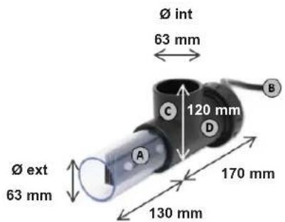
text_image
Ø int 63 mm 120 mm C D B Ø ext 63 mm 170 mm A 130 mmBOÎTIER ÉLECTRONIQUE
natural_image
Four black metal bracket clips with screws attached, arranged in a 2x2 grid (no text or symbols visible)
natural_image
Close-up of a black plastic clip holding a small metallic object with a wooden handle, against a dark surface (no text or symbols visible)
natural_image
Black rectangular object with four black metal clips attached, no visible text or symbols
m = 311
natural_image
Abstract geometric logo with stylized letter H inside a circular frame (no text or symbols)HAYWARD®

natural_image
Exterior view of a modern industrial air purifier unit with digital display and control buttons (no readable text or symbols)
text_image
CE iAquaRite LT
OWNER'S MANUAL
PLEASE KEEP THIS MANUAL FOR FUTURE REFERENCE
⚠ WARNING – Carefully read the instructions that appear in this manual and on the device. Failure to comply with the instructions can cause injuries. This document must be given to every pool user, who should keep it in a safe place.
⚠ WARNING – Disconnect the equipment from the mains supply before any intervention.
⚠ WARNING – All electrical connections must be carried out by a qualified approved electrician in accordance with the standards currently in force in the country of installation.
| F NF | C 15-100 GB BS7671:1992 | |||
| D DI | N VDE 0100-702 EW SIST HD 384-7-702.S2 | |||
| A | ÖVE 8001-4-702 | H | MSZ 2364-702:1994 / MSZ 10-533 1/1990 | |
| E | UNE 20460-7-702 1993, REBT ITC-BT-31 2002 | M | MSA HD 384-7-702.S2 | |
| IRL | IS HD 384-7-702 | PL | TS IEC 60364-7-702 | |
| I | CEI 64-8/7 | CZ | CSN 33 2000 7-702 | |
| LUX | 384-7.702 S2 | SK | STN 33 2000-7-702 | |
| NL | NEN 1010-7-702 | SLO | SIST HD 384-7-702.S2 | |
| P RS | UEE | TR TS | IEC 60364-7-702 | |
⚠ WARNING – Check that the device is plugged into a power outlet that is protected against short-circuits. The device must also be powered via an isolating transformer or a residual current device (RCD) with a nominal operating residual current not exceeding 30 mA.
⚠ WARNING- Ensure that children cannot play with the device. Keep your hands and any foreign object away from openings and moving parts.
⚠ WARNING – Check that the supply voltage required by the product corresponds to the voltage of the distribution network and that the power supply cables are suitable for the product power supply.
⚠ WARNING – Chemicals can cause internal and external burns. To avoid death, serious injury and/or damage to equipment, wear personal protective equipment (gloves, goggles, mask, etc.) when servicing or maintaining this device. This device must be installed in an adequately ventilated place.
⚠ WARNING – The unit shall not be operated when there is no water flow in the cell.
⚠ WARNING – The cell shall be located in a well ventilated environment so hazardous accumulation of hydrogen gas does not occur.
⚠ WARNING – To reduce the risk of electric shock, do not use an extension cable to connect the device to the mains. Use a wall socket.
⚠ WARNING – The appliance can be used by children aged from 8 years and above and persons with reduced physical, sensory or mental capabilities, or lack of experience and knowledge, if they have been given supervision or instruction concerning use of the appliance in a safe way and understand the hazards involved. Children must not play with the device. User maintenance and cleaning may only be carried out by children if they are at least 8 years old and are being supervised. Keep the device and the cable out of reach of children younger than 8 years old
⚠ WARNING – Use only original Hayward parts.
⚠ WARNING – If the power supply cable is damaged, it must be replaced by the manufacturer, the after-sales service or similarly qualified persons to avoid danger.
⚠ WARNING – The device must not be used if the power cord is damaged. An electric shock could occur. A damaged power cord must be replaced by the after-sales service or similarly qualified persons to avoid danger.
USE ONLY GENUINE REPLACEMENT PARTS
REGISTRATION
Thank you for choosing Hayward. This manual contains important information regarding the operation and maintenance of your product. Please retain it for reference.
TO REGISTER YOUR PRODUCT IN OUR DATABASE, GO TO:
www.hayward.fr/en/services/register-your-product

For Your Records
Record the following information for your convenience:
1) Purchase Date ____
2) Complete Name ____
3) Address ____
4) Zip code ____
5) Email Address ____
6) Part number ____ Serial number ____
7) Pool Dealer
8) Address
9) Zip code ____ Country ____
Note

GENERAL
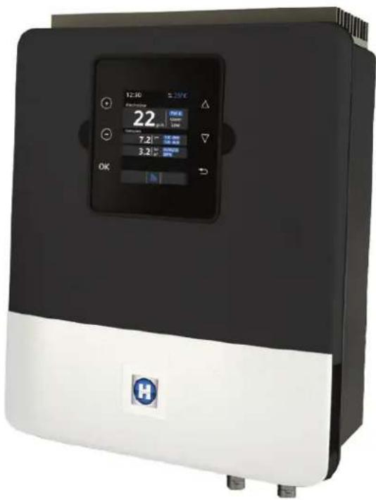
The AquaRite LT is a pool treatment system.
It can be used to treat your pool effectively by salt water electrolysis. For the chlorinator to function, it requires a low concentration of salt (sodium chloride) in the pool water. The Aqua Rite LT automatically disinfects your pool by converting the salt into free chlorine which kills the bacteria and algae in the pool. The chlorine reverts back to sodium chloride. This continuous cycle means that there is no need to treat your pool manually.
The AquaRite LT is suitable for treating most residential swimming pools.
The quantity of chlorine required to treat a swimming pool correctly varies according to the number of bathers, the rainfall, water temperature and the cleanliness of the pool...
NOTE: Before installing this product on the filtration system of a pool or spa with an adjacent natural stone terrace or deck, consult a qualified installer who will advise you on the type, installation, sealant (if any) and maintenance of stone that can be laid around a saline pool.
NOTE: The use of dry acid such as sodium bisulfate to adjust the pH of the swimming pool is not recommended, especially in arid regions where pool water is subject to significant evaporation and is not commonly diluted with mains water. Dry acid can cause a build-up of by-products that can damage your chlorinator.
INSTALLATION
Description
text_image
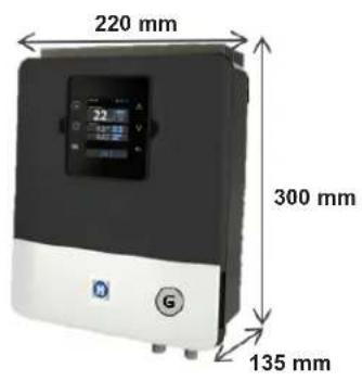
220 mm 300 mm 135 mm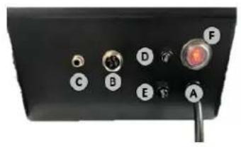
natural_image
Close-up of a black electronic device panel with labeled buttons (A–F) and a scroll wheel, no readable text or symbols beyond labels.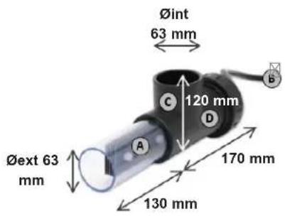
text_image
Øint 63 mm 120 mm Øext 63 mm 170 mm 130 mmELECTRONIC BOX
| A | Main connection 230 V - 50 Hz |
| B | Cell connection |
| C | Gas detector connection |
| D | 4 A Fuse |
| E | 4 A Fuse |
| F | pH and Rx connection |
| G | ON/OFF switch |
CELL
| A | Electrolysis cell |
| B | Connection to unit |
| C | Cell housing |
| D | Flow/gas detector (internal) |
USE ONLY GENUINE REPLACEMENT PARTS
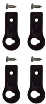
Wall-mounted installation
Fix the box and the measuring chamber on the wall (optional). The box must be installed in the equipment room (dry, temperate, ventilated). Caution, acid vapours can cause irreversible damage to your device. Position the treatment product tanks accordingly.
The AquaRite LT must be fitted a minimum horizontal distance of 3.5 m (or more, if required by local regulations) from the pool, within 1 m of a protected outlet and within 4.5 m of the planned cell location.
The box must be placed vertically on a flat surface, with the cables downwards. As this box is also used to evacuate heat (heat dissipation from internal components), it is important that the four sides of the box remain unobstructed. Do not to install the AquaRite LT behind a panel or in an enclosed space.
Before installing the control unit in the intended location, check that the power cord can reach the protected outlet and that the cell cable can reach the intended cell location.
natural_image
Four black metal bracket clips with screws attached, arranged in a 2x2 grid (no text or symbols)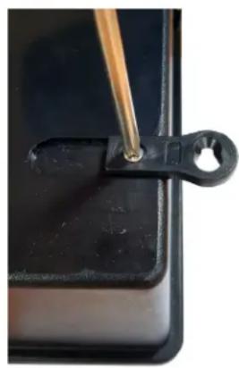
natural_image
Close-up of a black plastic clip holding a small hole, with a wooden tool inserted (no text or symbols visible)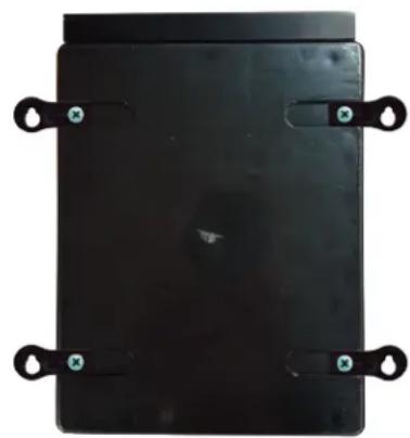
natural_image
Top-down view of a black rectangular electronic device with four metallic clips and mounting holes (no text or symbols visible)Disconnect the pool filtration pump before starting the installation. The system must be installed in accordance with the standards currently in force in the country of installation. The control box must be fitted a minimum horizontal distance of 3.5 m (or more, if required by local regulations) from the pool, within 1 m of a protected outlet and 4.5 m of the planned cell location. Install and use the product at an altitude below 2000 m.
The flow switch must be installed on the return pipe directly in line with and upstream of the cell and the treatment product injection point. Allow a 25 cm straight section before the flow switch. A hole should previously have been drilled in the pipe to allow the flow switch to pass through. Screw the flow switch into the saddle clamp, taking care to seal with Teflon. Then install the clamp on the pipe. The flow switch must be installed in the direction of operation to ensure that it is tripped by the flow from the filtration pump.
All the metal components of the swimming pool can be connected to the same earth as per local regulations.

HAYWARD®
Kit pH Standard / Kit ORP Standard (optional)
text_image
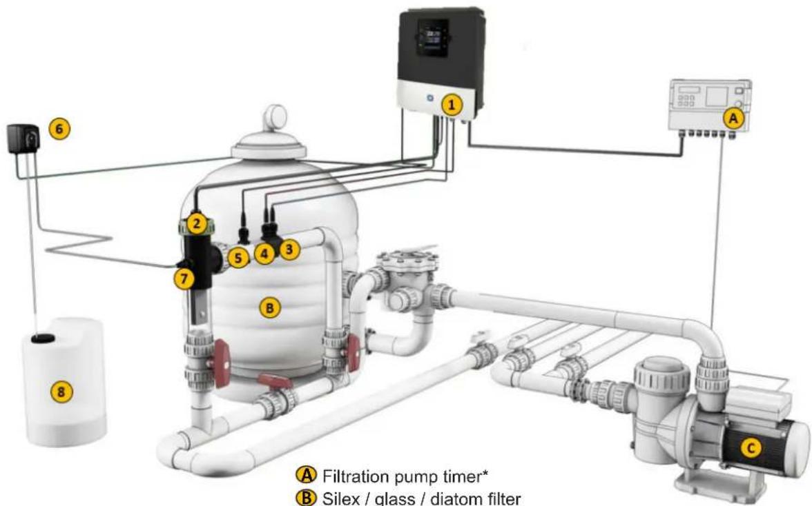
① ② ③ ④ ⑤ ⑥ ⑦ ⑧ A Filtration pump timer* B Silex / glass / diatom filter CⒶ Filtration pump timer*
B Silex / glass / diatom filter
C Recirculation pump
① Electronic box
② Electrolysis cell (always vertical)
③ pH probe (optional)
④ Rx probe (optional)
⑤ Temperature probe (optional)
⑥ Acid dosing pump (optional)
⑦ Acid injector (optional)
⑧ Sulphuric acid container (not supplied)
USE ONLY GENUINE REPLACEMENT PARTS

HAYWARD®
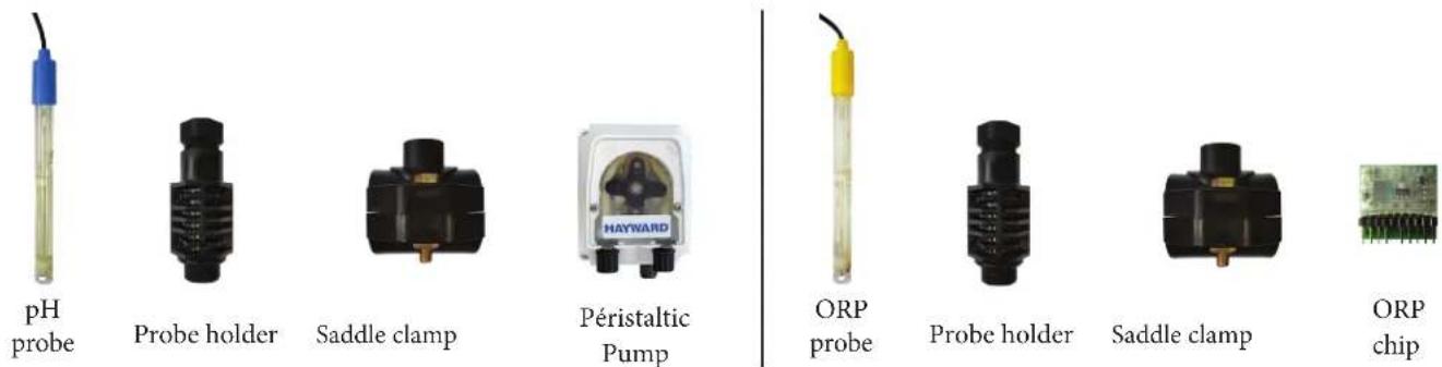
Installing the pH and ORP probes
The pH and ORP probes are «wet» packed and protected by a plastic cap. The probes must always remain wet. If the probes are allowed to dry, they will be permanently unusable (not covered by the warranty) and the pH-ORP test kit will be ineffective.
Remove the pH and ORP probes from their plastic protective caps and set the caps aside for later use (wintering). Insert the probes into the probe holder and tighten to ensure that they are watertight. Place the probe holder on the saddle clamp and tighten by hand only. Check that the probes are watertight at startup. Seal with Teflon, if required.
After installation, check that the probes are constantly in contact with the water in the pool. When the filtration pump is not running (even for long periods), the water remaining in the chamber may be sufficient to protect the probes. The product (acid, etc.) injection device must be installed last on the water return line, after any equipment (heater, cell, etc.). A hole should previously have been drilled in the pipe to allow the treatment product to pass through. Install the saddle clamp and screw the injection valve into the saddle clamp using the adapter provided. Seal with Teflon.
Use the transparent PVC hose for suction (between the acid tank and the peristaltic pump) and the semi-rigid white polyethylene tube for injection (between the peristaltic pump and the injection valve).
For the ORP option, install the ORP card in the RX slot on the motherboard.
Electrical installation and wiring
Connect the AquaRite LT to a permanent power outlet.
⚠: This circuit must be protected by a residual current device (RCD) (residual current: 30 mA max.).
text_image
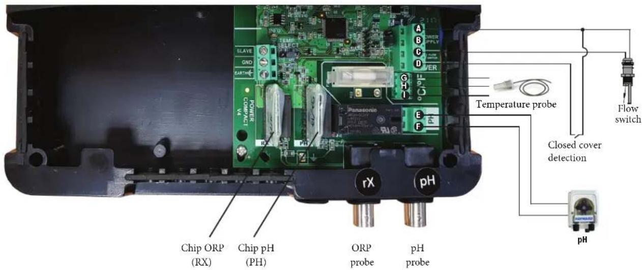
Temperature probe Flow switch Closed cover detection Chip ORP (RX) Chip pH (PH) ORP probe pH probe rX pHConnecting inputs:
| Name Description Terminals Type of input/output | |||
| FL1 Flow switch: A - C Dry contact | |||
| Cover Closed | cover detection A - D Dry contact | ||
| pH Peristaltic pump (optional) E - F | 230 V ^v voltage output | ||
| °C/°F | Temperature probe | G - I | G-Red, H-Yellow, I-Black (V1)G-Brown, H-Yellow, I-White (V2) |
Connect the flow switch supplied to input terminals A and C.
USE ONLY GENUINE REPLACEMENT PARTS
Direction of chips
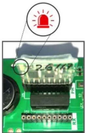
text_image
26149 RX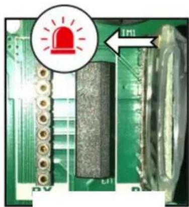
natural_image
Close-up of a green printed circuit board with visible components and a red warning light icon (no text or symbols)
text_image
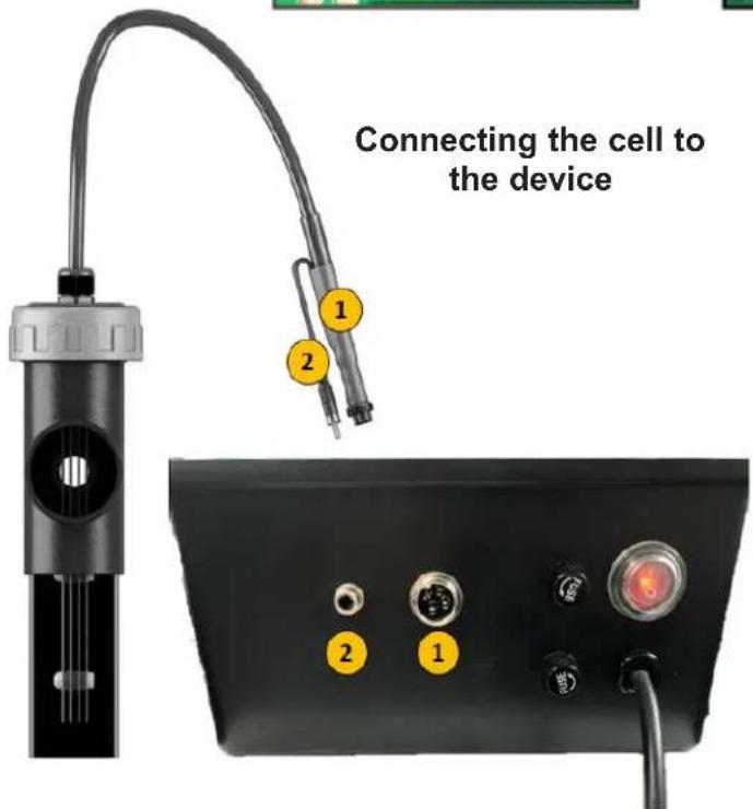
Connecting the cell to the device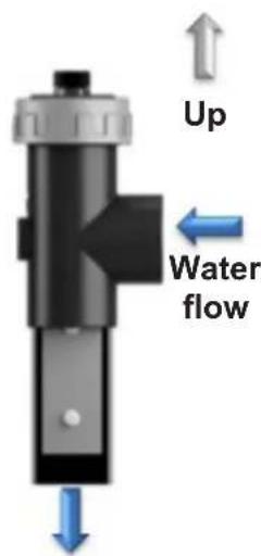
text_image
Up Water flowFlow of water through the installation
Attention
Installation of the cell in a vertical position inside the pipe is recommended.
If it is installed horizontally, it is compulsory to add a mechanical flow switch (available as an option) and to suitably adapt the configuration of the device.
Preparing the pool water
To prepare the pool water to enable the AquaRite LT to function, its chemical composition must be balanced and salt added. This must be done BEFORE turning on the AquaRite LT. Certain adjustments to the chemical balance of the pool can take several hours. The procedure must therefore be started well before the AquaRite LT is turned on.
Adding salt: Add the salt several hours or, if possible, a day before turning on the AquaRite LT. Ensure that the recommended amount of salt is used. Measure the salt content 6 to 8 hours after adding the salt to the swimming pool.
NOTE: If the water in the pool is not fresh and/or if it is liable to contain dissolved metals, use a metal remover, according to the manufacturer's instructions.
If your water has previously been treated with a product other than chlorine (bromine, hydrogen peroxide, PHMB, etc.), neutralize this product or replace all the water in the pool.
Salt concentration
Use the following table to determine the quantity of salt (in kg) needed to reach the recommended concentrations. Use the formulae below if you do not know the volume of your swimming pool.
| m3(pool dimensions, in m) | |
| Rectangular | Length x width xAverage depth |
| Round | Diameter x Diameter xAverage depth x 0.785 |
| Oval | Length x width xAverage depth x 0.893 |
The ideal salt concentration is between 2.7 and 3.4 g/l, with 3.2 g/l being the optimum value. If the level is low, determine the volume ( m^3 ) of the pool and add salt in accordance with the following table. A low salt level reduces the efficiency of the AquaRite LT and reduces chlorine production. A high salt concentration can cause the AquaRite LT to fail and make your pool water taste salty. As the salt in your pool is constantly being recycled, the loss of salt during the season is minimal. Salt is mainly lost when water has to be added due to splashing, backwashing or draining (because of rain). Salt is not lost through evaporation.
Type of salt to use
Use only salt intended for chlorinators in conformance with EN 16401. Use only sodium chloride (NaCl) that is more than 99% pure. Do not use food-grade salt, iodized salt, salt containing yellow prussiate of soda or salt containing anti-caking additives.
How to add or remove salt
For new pools, let the plaster dry for ten to fourteen days before adding salt. Start up the filtration pump, then add salt directly into the intake side of the pool. Make the water circulate to speed up the dissolution process. Do not allow salt to accumulate at the bottom of the pool. Run the filtration pump for 24 hours, opening the main drain valve fully to allow the salt to dissolve evenly throughout the pool.
The only way to lower the salt concentration is to partially empty the pool and refill it with fresh water.
Always check the stabilizer (cyanuric acid) when checking the salt concentration. The corresponding concentrations tend to decrease together. Refer to the following table to determine the quantity of stabilizer to be added to bring the concentration to 25 ppm. Add stabilizer only if necessary.
Do not add stabilizer to indoor pools.
USE ONLY GENUINE REPLACEMENT PARTS
Quantity of salt (kg) required for 3.2 g/l
| Current salt concentration in g/l | Volume of water in the pool in m^3 | ||||||||||||||||
| 30 37.5 | 45 52.5 | 60 67.5 | 75 82.5 | 90 97.5 | 105 112.5 | 120 127.5 | 135 142.5 | 150 | |||||||||
| 0 | 97 121 | 145 170 | 194 218 | 242 | 267 291 | 315 | 339 364 | 388 412 | 436 | 460 484 | |||||||
| 0.2 | 91 114 | 136 159 | 152 205 | 227 | 250 273 | 295 | 318 341 | 363 385 | 408 | 430 453 | |||||||
| 0.4 | 85 100 | 127 148 | 170 191 | 212 | 233 255 | 276 | 297 318 | 239 360 | 382 | 403 424 | |||||||
| 0.6 | 79 98 | 18 138 | 158 177 | 197 217 | 217 236 | 256 | 276 297 | 317 337 | 358 | 378 398 | |||||||
| 0.8 | 73 91 | 09 127 | 145 164 | 182 220 | 200 218 | 236 | 255 273 | 291 310 | 328 | 346 364 | |||||||
| 1 | 67 83 | 00 117 | 135 150 | 167 118 | 183 200 | 217 | 233 250 | 267 283 | 300 | 317 333 | |||||||
| 1.2 | 61 76 | 91 106 | 121 136 | 152 167 | 182 197 | 212 | 227 243 | 258 274 | 289 | 304 | |||||||
| 1.4 | 55 68 | 42 95 | 109 123 | 136 150 | 164 177 | 191 | 205 218 | 232 246 | 259 | 263 | |||||||
| 1.6 | 48 61 | 73 85 | 97 109 | 121 133 | 145 158 | 170 | 182 195 | 207 219 | 231 | 243 | |||||||
| 1.8 | 42 53 | 64 74 | 85 95 | 106 117 | 127 138 | 148 | 159 169 | 180 190 | 201 211 | ||||||||
| 2 | 36 45 | 55 64 | 73 82 | 91 100 | 109 118 | 127 136 | 145 154 | 163 172 | 181 | ||||||||
| 2.2 | 30 38 | 45 53 | 61 68 | 76 83 | 91 98 | 106 114 | 121 129 | 137 144 | 152 | ||||||||
| 2.4 | 24 30 | 46 42 | 48 55 | 61 67 | 73 79 | 85 91 | 98 110 | 117 123 | |||||||||
| 2.6 | 18 23 | 27 32 | 36 | 41 45 | 50 55 | 59 64 | 68 73 | 77 81 | 86 90 | ||||||||
| 2.8 | 12 15 | 8 21 | 24 27 | 30 33 | 36 39 | 42 45 | 48 51 | 54 57 | 60 | ||||||||
| 3 | 6 8 9 | 11 12 | 14 15 | 17 18 | 20 21 | 23 24 | 26 27 | 29 30 | |||||||||
| 3.2 | Ideal Ideal Ideal Ideal Ideal Ideal Ideal Ideal Ideal Ideal Ideal Ideal Ideal Ideal Ideal Ideal Ideal Ideal Ideal Ideal Ideal Ideal Ideal Ideal Ideal Ideal Ideal Ideal Ideal Ideal Ideal Ideal Ideal Ideal Ideal Ideal Ideal Ideal Ideal Ideal Ideal Ideal Ideal Ideal Ideal Ideal Ideal Ideal Ideal Ideal Ideal Ideal Ideal Ideal Ideal Ideal Ideal Ideal Ideal Ideal Ideal Ideal Ideal Ideal Ideal Ideal Ideal Ideal Ideal Ideal Ideal Ideal Ideal Ideal Ideal Ideal Ideal Ideal Ideal Ideal Ideal Ideal Ideal Ideal Ideal Ideal Ideal Ideal Ideal Ideal Ideal Ideal Ideal Ideal Ideal Ideal Ideal Ideal Ideal Ideal Ideal | ||||||||||||||||
| 3.4 | OK OK | OK OK | OK OK | OK OK | OK OK | OK OK | OK OK | OK OK | OK OK | ||||||||
| 3.6 & + | Diluted | Diluted | Diluted | Diluted | Diluted | Diluted | Diluted | Diluted | Diluted | Diluted | Diluted | Diluted | Diluted | Diluted | Diluted | Diluted | Diluted |
Quantity of stabilizer (CYANURIC ACID in kg) required for 25 ppm
| Current salt concentration (ppm) | Volume of water in the pool in m^3 | ||||||||||||||||
| 30 37.5 45 52.5 60 67.5 75 82.5 90 97.5 105 112.5 120 127.5 135 142.5 150 | |||||||||||||||||
| 0 ppm | 0.75 | 0.94 | 1.13 | 1.34 | 1.53 | 1.69 | 1.91 | 2.09 | 2.28 | 2.47 | 2.66 | 2.84 | 3.03 | 3.22 | 3.41 | 3.59 | 3.75 |
| 10 ppm | 0.45 | 0.56 | 0.68 | 0.81 | 0.92 | 1.01 | 1.14 | 1.26 | 1.37 | 1.48 | 1.59 | 1.71 | 1.82 | 1.93 | 2.04 | 2.16 | 2.25 |
| 20 ppm | 0.15 | 0.19 | 0.23 | 0.27 | 0.31 | 0.34 | 0.38 | 0.42 | 0.46 | 0.49 | 0.53 | 0.57 | 0.61 | 0.64 | 0.68 | 0.72 | 0.75 |
| 25 ppm | 0 0 0 0 | 0 0 0 0 0 0 | 0 0 0 0 0 0 0 | ||||||||||||||
Chemical water balance
The water must be balanced manually BEFORE the device is started up.
The following table summarizes the concentrations recommended by Hayward. Your water should be checked regularly to maintain these concentrations and minimize surface corrosion or deterioration.
CHEMISTRY RECOMMENDED CONCENTRATIONS
| Salt 3,2 g/l | |
| Free chlorine 1.0 to 3.0 ppm | |
| pH 7.2 to 7.6 (7.2 recommended). | |
| Cyanuric acid(Stabilizer) | 20 to 30 ppm max.(Add stabilizer only if necessary)0 ppm in indoor pool |
| Total alkalinity 80 to 120 ppm | |
| Water hardness 200 to 300 ppm | |
| Metals 0 ppm | |
| Saturation index -0.2 to 0.2 (preferably 0) | |
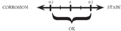
Saturation index
The saturation index (Si) gives us information about the calcium content and alkalinity of the water; it is a water balance indicator. Your water is correctly balanced if the Si is 0 ± 0.2 . If the Si is below -0.2, the water is corrosive and the coating on the pool walls may be damaged. If the Si is above +0.2, stains may appear. Use the table below to determine the saturation index.
Use: Measure the pH of the pool water, the temperature, water hardness and total alkalinity. Use the table above to determine Ti, Ci and Ai in the formula shown above. If the Si is equal to 0.2 or more, stains may appear. If the Si is equal to -0.2 or less, corrosion or deterioration may occur.
text_image
CORROSION 0.2 0 0.2 STAIN OK⚠ WARNING – Chemicals can cause internal and external burns. To avoid death, serious injury and/or damage to equipment, wear personal protective equipment (gloves, goggles, mask, etc.) when servicing or maintaining this device. This device must be installed in an adequately ventilated place.
USE ONLY GENUINE REPLACEMENT PARTS
OPERATION
The device is designed to be connected to a protected outlet at all times. The AquaRite LT must not be disconnected unless the pool equipment is undergoing maintenance or the pool is to be closed (wintering).
Assuming that the chemical balance of the water is within the recommended ranges, the device can be started up.
Configuration
text_image
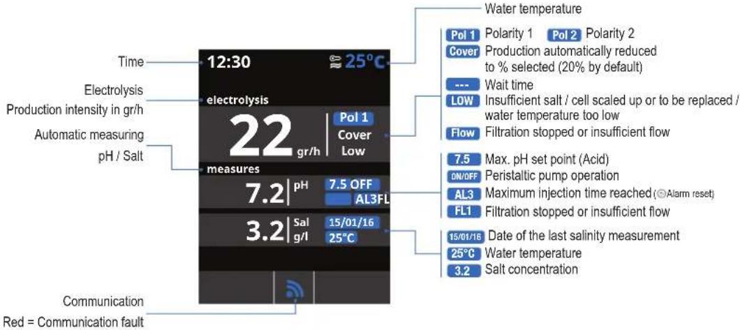
Time Electrolysis Production intensity in gr/h Automatic measuring pH / Salt 12:30 electrolysis 22 gr/h Measures 7.2 | pH 7.5 OFF AL3FL 3.2 | Sal 15/01/16 g/l 25°C Communication Red = Communication fault Water temperature Pol 1 Polarity 1 Pol 2 Polarity 2 Cover Production automatically reduced to % selected (20% by default) --- Wait time LOW Insufficient salt / cell scaled up or to be replaced / water temperature too low Flow Filtration stopped or insufficient flow 7.5 Max. pH set point (Acid) ON/OFF Peristaltic pump operation AL3 Maximum injection time reached (© Alarm reset) FL1 Filtration stopped or insufficient flow 15/01/16 Date of the last salinity measurement 25°C Water temperature 3.2 Salt concentrationSettings
flowchart
graph TD
A["Main menu"] --> B["Settings"]
B --> C["Language"]
C --> D["Time"]
D --> E["Network"]
E --> F["Screen"]
F --> G["OK"]
H["Langue"] --> I["Espanol"]
I --> J["English"]
J --> K["Français"]
K --> L["Deutsch"]
M["Language"] --> N["Espanol"]
N --> O["English"]
O --> P["Français"]
P --> Q["Deutsch"]
R["Settings"] --> S["Language"]
S --> T["Time"]
T --> U["Network"]
U --> V["Screen"]
W["Time"] --> X["15:09:37"]
X --> Y["Date 20/02/2016"]
Z["Settings"] --> AA["Language"]
AA --> AB["Time"]
AB --> AC["Network"]
AC --> AD["Screen"]
AE["Settings"] --> AF["Intensity 100%"]
AF --> AG["Sleep Always ON"]
AH["Settings"] --> AI["Time"]
AI --> AJ["Network"]
AJ --> AK["Screen"]
AK --> AL["Sound"]
AM["Settings"] --> AN["Keyboard On Off"]
AN --> AO["Pop-ups On Off"]
AO --> AP["Alerts On Off"]
AQ["Settings"] --> AR["Network"]
AR --> AS["Screen"]
AS --> AT["Sound"]
AT --> AU["Password"]
AV["Password"] --> AW["Please enter a 5 key password"]
AX["Settings"] --> AY["Sound"]
AY --> AZ["Password"]
AZ --> BA["Cell hours"]
BA --> BB["System info"]
BC["Settings"] --> BD["Sound"]
BD --> BE["Password"]
BE --> BF["Cell hours"]
BF --> BG["System info"]
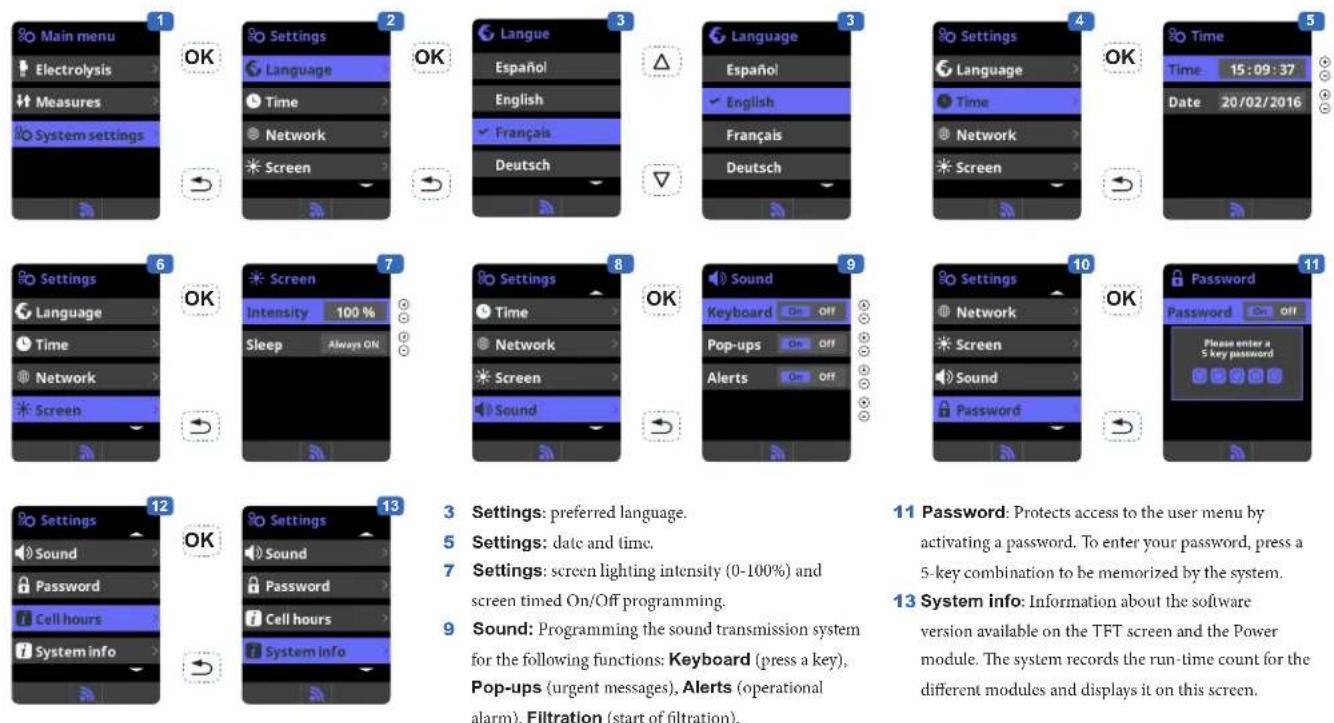
BH["Settings"] --> BI["Preferred language"]
BI --> BJ["Date and time"]
BK["Settings"] --> BL Screen lighting intensity (0-100%) and screen timed on/off programming.
BL = Screen lighting intensity (0-100%) and screen timed on/off programming.
BN = Programming the sound transmission system for the following functions:
Keyboard (press a key),
Pop-ups (urgent messages),
Alerts (operational alarm),
Filtration (start of filtration).
BO["Settings"] --> BP["Protects access to the user menu by activating a password. To enter your password, press a 5-key combination to be memorized by the system."]
BQ["System info"] --> BR["Information about the software version available on the TFT screen and the Power module. The system records the run-time count for the different modules and displays it on this screen."]
USE ONLY GENUINE REPLACEMENT PARTS
Electrolysis
flowchart
graph LR
    A["Main menu"] --> B["Electrolysis"]
    B --> C["Measures"]
    C --> D["System settings"]

    D --> E["OK"]

    E --> F["Electrolysis"]
    F --> G["Salinity 30 g/l"]
    G --> H["Salinity On Off"]
    H --> I["Cover On Off"]
    I --> J["Reduction 20%"]

    J --> K["OK"]

    K --> L["Electrolysis"]
    L --> M["Salinity 30 g/l"]
    M --> N["Salinity On Off"]
    N --> O["Boost On Off"]
    O --> P["Cover On Off"]
    P --> Q["Off temp. 10 °C"]
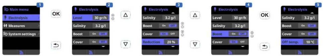
1 Electrolysis: Electrolysis function programming.
2 Level: Chlorine production (gr/h) required.
3 Cover: Closed cover safety activation.
Reduction: % of chlorine production when the cover is closed (20% by default).
4 Boost (Super Chlorination): Filtration and continuous production of chlorine for 24 hours (maximum production level). Automatic return to the filtration and production mode programmed after the 24 hours.
5 Off Temp: Sets the temperature beyond which the salt chlorinator will cut off. This temperature must be between 15^ C and 10^ C.
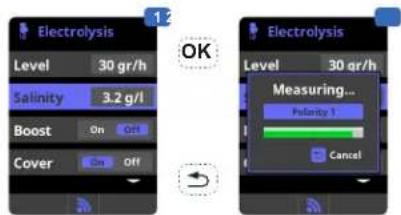
Salt concentration
text_image
Electrolysis Level 30 gr/h Salinity 3.2 g/l Boost On Off Cover On Off 12 OK Electrolysis Level 30 gr/h Measuring... Polarity 1 Cancel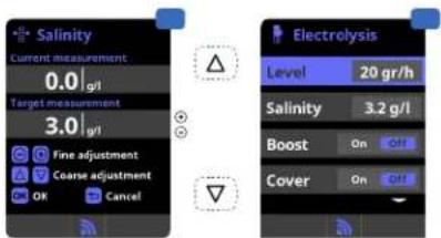
text_image
Salinity Current measurement 0.0 | g/l Target measurement 3.0 | g/l Fine adjustment Coarse adjustment OK Cancel Electrolysis Level 20 gr/h Salinity 3.2 g/l Boost On Off Cover On OffSetting the pH correction time
text_image
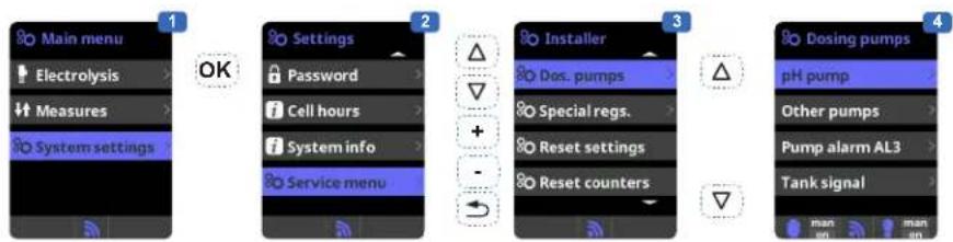
Main menu Electrolysis Measures System settings OK Settings Password Cell hours System info Service menu Installer Dos. pumps Special regs. Reset settings Reset counters Dosing pumps pH pump Other pumps Pump alarm AL3 Tank signal man man1 Salt concentration measurement.
2 Enter in the Salinity menu, use Enter to measure the salt concentration for polarity 1, then for polarity 2. This measurement can only be done manually. It will have to be taken periodically.
3 Adjustment: Once the measurement has been taken, you can adjust the salt level manually.
4 Display: Once the salt concentration has been measured, it is displayed on the salt chlorination screen and the main screen.
text_image
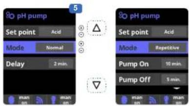
pH pump Set point Acid Mode Normal Delay 2 min. man man 5 pH pump Set point Acid Mode Repetitive Pump On 10 min. Pump Off 5 min. man man1 Setting the pH correction time.
The chemical parameters of the water must be set manually before the device is started up. If these adjustments are not made in advance, unwanted AL3 alarms may be tripped.
2 Enter the password: △▽⊕⊖
3 Select the "Dos. pumps" menu.
4 Select the "pH pump" menu.
5 Normal mode:
- Delay: Time delay between detection of an incorrect value and activation of the dosing pump.
6 Repetition mode :
- Pump On: pH pump operating time.
- Pump Off: pH pump downtime.
- Scaling: Determines the percentage injected by the dosing pump (0% = no injection, 100% = maximum dosing).
- The cycles are repeated until the selected setpoint value is reached.
Measures
text_image
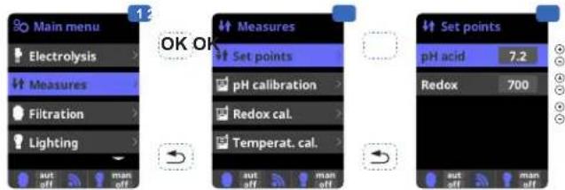
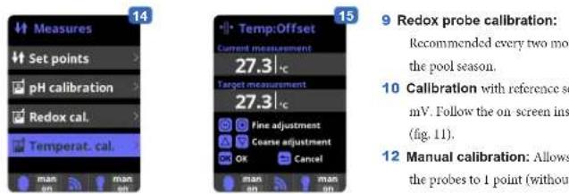
Main menu Electrolysis Measures Filtration Lighting aut off man off OK OK Measures Set points pH calibration Redox cal. Temperat. cal. aut off man off Set points pH acid 7.2 Redox 7001 Measures: Adjustment of set points and measuring probes.
2 Set points for each measurement.
3 Setting the set points.
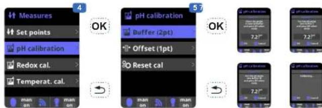
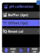
4 pH probe calibration: Recommended once a month during the pool season.
5 Calibration using buffer solutions (liquids models pH7 / pH10 / neutral). Follow the on-screen instructions (fig. 6).
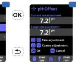
7 Manual calibration: Allows you to set the probes to 1 point (without buffer solution) – recommended only for adjusting small deviations in readings.
text_image
Measures Set points pH calibration Redox cal. Temperat. cal. 4 OK 5 OK pH calibration Buffer (2pt) Offset (1pt) Reset cal man on man on 7 OK pH calibration Buffer (2pt) Offset (1pt) Reset cal man on man on 7.2" 7.2"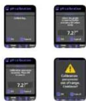
text_image
OK pH:Offset Current measurement 7.2 | pH Target measurement 7.2 | pH Fine adjustment Coarse adjustment OK Cancel man an man on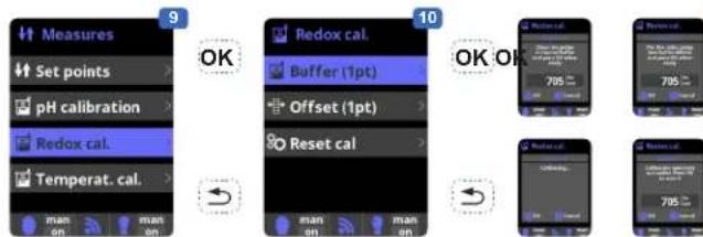
text_image
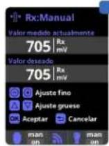
Measures Set points pH calibration Redox cal. Temperat. cal. 9 OK 10 Redox cal. Buffer (1pt) Offset (1pt) Reset cal 705 705 705 705 705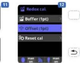
text_image
Redox cal. Buffer (1pt) Offset (1pt) Reset cal man on man on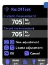
8 Without removing the probe from the water, use the + / - keys to adjust the reading to your reference value (photometer or other measuring instrument).
text_image
14 Measures Set points pH calibration Redox cal. Temperat. cal. man on man on Temp:Offset Current measurement 27.3 | c Target measurement 27.3 | c Fine adjustment Coarse adjustment OK Cancel man on man on 15 9 Redox probe calibration: Recommended every two mo the pool season. 10 Calibration with reference se mV. Follow the on-screen ins (fig. 11). 12 Manual calibration: Allows the probes to 1 point (without- recommended only for adjusting small during deviations in readings.
13 Without removing the probe from the water, use the + / - keys to adjust the reading to your reference value (photometer or other measuring instrument).
14 Temperature probe calibration: Allows you to set the probes to 1 point.
15 Without removing the probe from the water, use the + / - keys to adjust the reading to your reference value (thermometer). The same conditions should apply for measurements.
Setting the redox level (redox kit option)
The redox level tells you the oxidation potential, i.e. the disinfectant capacity of the water.
Setting the redox set point is the last step in setting the AquaRite LT.
To find the optimum redox level for your pool, follow the steps below:
1) Start up the pool filtration system (the salt in the pool must be evenly dissolved).
2) Add chlorine to the swimming pool until it reaches 1 to 1.5ppm . This level is achieved with (approximately 1 to 1.5g / m^3 of water). The pH level must vary between 7.2 and 7.5.
3) After 30 min. Check whether the level of free chlorine in the pool (manual DPD1 test kit) is between 0.8 and 1.0 ppm.
4) Look at the redox value on the screen and enter it as the redox set point.
5) The next day, check the free chlorine levels (manual DPD1 test kit) and the redox level. Increase / reduce the setting, if required. Remember to check all your water parameters at regular intervals (2-3 months) (see table) and adjust the redox set point according to the steps listed above.
SERVICING
During the first 10-15 days, your system will require more attention:
- Check that the pH remains at the ideal level (7.2 to 7.4).
- If the pH is exceptionally unstable and uses a lot of acid, check the alkalinity (see table).
If the balance is highly unstable, contact your pool installer/builder.
REMEMBER that the system needs a certain amount of time to adapt to your pool and will require additional chemicals during the first 3-5 days.
The pool must be regularly maintained and the skimmer baskets emptied whenever necessary.
Also check that your filter is not clogged.
ADD WATER: It is preferable to add water via the skimmers so that it passes through the cell before entering the pool. Remember to check the salt percentage after adding water.
DOSING PUMPS: Regularly check the acid level to ensure that the pump does not run dry. The dosing pump must be checked and serviced at regular intervals.
Servicing the probe
The probe must be clean and free from oil, chemical deposits and contamination to function properly. As it is in continuous contact with the water in the pool, the probe may need to be cleaned weekly or monthly, depending on the number of bathers and other specific pool characteristics. A slow response, more frequent pH calibration and inconsistent readings indicate that the probe need to be cleaned.
To clean the probe, turn off the power to the AquaRite LT.
Unplug the probe connector from the control box, unscrew the probe and carefully remove it from the chamber. Clean the probe bulb with a soft toothbrush and regular toothpaste.
A household washing-up liquid detergent may also be used to remove any oil.
Rinse with fresh water, replace the Teflon tape on the threads, and reinstall the probe.
If the probe continues to give inconsistent readings or requires excessive calibration after it has been cleaned, it should be replaced.
Servicing and cleaning the AquaRite LT cell
Turn off the main power supply to the AquaRite LT before removing the cell. Once it has been removed, examine the inside of the cell for any traces of scale (whitish brittle or flaky deposits) and debris stuck to the plates. If no deposits are visible, reinstall the cell. If deposits are visible, try to remove them with a garden hose. If this method is unsuccessful, use a plastic or wooden tool to remove deposits stuck to plates (do not use a metal tool as this will damage their coating). A build-up of deposits on the cell indicates an exceptionally high concentration of calcium in the pool water. If you cannot find a solution to this situation, you will have to clean the cell at regular intervals. The best way to avoid this problem is to maintain the chemical composition of the water at the recommended concentrations.
Acid washing: This should only be done in severe cases where flushing will not remove most of the deposits. To acid wash, turn off the main power supply to the AquaRite LT. Remove the cell from the piping. In a clean plastic container, make up a solution of water and acetic or phosphoric acid (such as that used to remove scale from a coffee machine). ALWAYS ADD ACID TO WATER – NEVER ADD WATER
TO ACID. Be sure to wear rubber gloves and protective goggles for this operation. The level of the solution in the container should just reach the top of the cell, so that the wire harness compartment IS NOT under water. It may be helpful to coil up the wire before submerging the cell. Allow the cell to soak for a few minutes, then rinse it with a garden hose. If the deposits are still visible, soak and rinse again. Put the cell back and examine it from time to time.
Wintering
The AquaRite LT cell, the flow switch, probe and pool piping run the risk of being damaged if the water freezes. In regions that experience long periods of cold weather, be sure to drain all the water from the pump and filter and from the supply and return pipes before winter. Do not remove the control unit.
Probe storage
The end of the probe must always be in contact with water or a solution of KCl. If it is removed from the measuring chamber, it should be stored in the plastic cap provided (filled with water). If the storage cap has been mislaid, the probe should be stored separately in a small glass or plastic container with its end immersed in water.
The probe must always be in a frost-free environment.
USE ONLY GENUINE REPLACEMENT PARTS
TROUBLESHOOTING GUIDE
No display
Check that the On / Off switch is on.
Check the connection cable between the display and the control box.
Check that the external 4A fuse (7) is not defective.
Check the power supply: 210-230 V\~ 50 Hz.
If the problem persists, contact your pool installer/builder.
Excessive chlorine
Low electrolytic cell current.
If your pool has an automatic redox control system, check the redox setting.
Check the redox probe and calibrate, if necessary.
Salt chlorination does not reach the required production rate
Check the concentration of salt in the water (3.2 g/l recommended).
Check the condition of the cell (it may be dirty or covered in scale).
Clean the cell according to instructions.
Check the flow switch and clean if necessary.
Check that the cell is not worn (contact your pool installer/builder).
Cell scaled up in under a month
Very hard water with high pH and total alkalinity (balance and adjust the pH and total alkalinity of the water).
Check that the system automatically changes polarity (see display).
Impossible to attain a free chlorine level of 1 ppm
Increase the filtration time.
Increase the chlorination production rate.
Check the concentration of salt in the water (recommandé 3.2 g/l).
Check the level of isocyanuric acid in the pool (see table).
Check that the reactive agents in your test kit are not out of date.
Adjust the chlorine production according to the temperature and the number of pool users.
Adjust the pH to ensure that it is always below 7.8 (7.2 recommended).
Alarm AL3: pH dosing pump stopped
The maximum time allowed to attain the pH set point has been reached. The pH acid dosing pump is stopped to avoid overdosing and acidifying the water.
Please carry out the following checks to avoid equipment failure:
Check that the can of liquid pH is not empty.
Check whether the pH read on the machine corresponds to the pH in the pool (use a pH analysis kit). Otherwise, please calibrate the pH probe or replace it, if necessary.
Check that the pH pump is running normally.
Check the correction time setting.
To delete this message and reset the dosing, press the "Return" key.
The screen indicates LOW
Check the water balance and salinity.
Check that the cell is free of scale and clean it if necessary.
See "Salt chlorination does not reach the required production rate".
Water temperature too low.
White flakes in the pool
This occurs when the water is unbalanced and very hard.
Balance the water, check the cell and clean it, if necessary.
The screen indicates FLOW
Check the flow switch.
Check that the filter pump is working.
Check that the pipes are not obstructed (valve closed, basket or strainer full, etc.).
Check 4 A fuse (6).
USE ONLY GENUINE REPLACEMENT PARTS

natural_image
Abstract geometric logo with stylized letter H inside a circular frame (no text or symbols)HAYWARD®

natural_image
Exterior view of a modern industrial air conditioning unit with digital display and control buttons (no readable text or symbols)
text_image
CE iAquaRite LT
MANUAL DEL USUARIO
CONSERVE ESTE MANUAL PARA CONSULTAS ULTERIORES


natural_image
Close-up of a black electronic device panel with labeled buttons (A–F) and a cable, no readable text or symbols beyond component labels.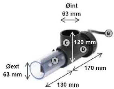
text_image
Øint 63 mm 120 mm 170 mm 130 mm Øext 63 mm A B C DCAJA ELECTRÓNICA
| A | Alimentación 230 V - 50 Hz |
| B | Conexión célula |
| C | Conexión flow gas |
| D | Fusible 4 A |
| E | Fusible 4 A |
| F | Conexión pH y Rx |
| G | Interruptor ON / OFF |
CÉLULA
natural_image
Four black metal bracket clips with screws attached, arranged in a 2x2 grid (no text or symbols)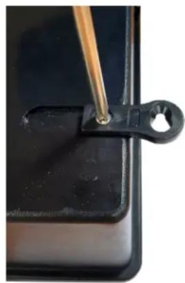
natural_image
Close-up of a black plastic clip holding a wooden stick, with no visible text or symbols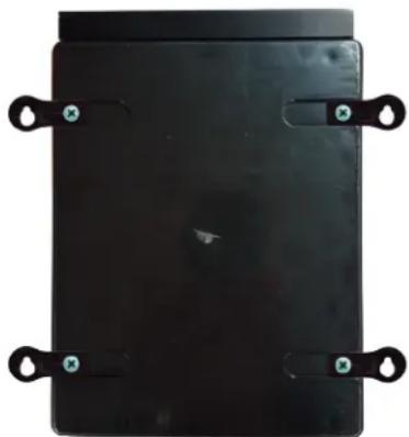
natural_image
Black rectangular electronic device with four metallic clips and mounting holes (no visible text or symbols)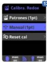
12
The image contains no discernible text or characters.
[Non-Text]
natural_image
Abstract geometric logo with stylized letter H inside a circular frame (no text or symbols)HAYWARD®

natural_image
Exterior view of a modern industrial air conditioning unit with digital display and control buttons (no readable text or symbols)
text_image
CE iAquaRite LT
MANUAL DO UTILIZADOR
GUARDE ESTE MANUAL PARA REFERÊNCIA FUTURA
www.hayward.fr/en/services/register-your-product
Para seu registo
text_image
Control panel with labeled buttons A through F, showing various function keys and indicators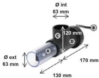
text_image
Ø int 63 mm 120 mm C D B Ø ext 63 mm 170 mm 130 mmCAIXA DA ELETRÓNICA
natural_image
Four identical black metal bracket components with four screws attached (no text or symbols)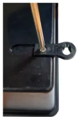
natural_image
Close-up of a black plastic clip holding a small hole, with a wooden tool inserted (no text or symbols visible)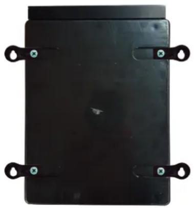
natural_image
Black rectangular object with four circular side handles and small green markers, no visible text or symbols.natural_image
Pure mechanical component diagram without any text, numbers, or symbolstext_image
Eletrólise Level 20 gr/h Salinity 3.2 g/l Shock On Off Cover On Off Eletrólise Level 20 gr/h Measuring... Polarity 1 Cancel Salinity Current measurement 0.0 | g/l Target measurement 3.2 | g/l Fine adjustment Coarse adjustment OK Cancel Eletrólise Level 20 gr/h Salinity 3.2 g/l Shock On Off Cover On Offnatural_image
Abstract geometric logo with stylized letter H inside a circular frame (no text or symbols)HAYWARD®

natural_image
Exterior view of a modern industrial air purifier unit with digital display and control buttons (no readable text or symbols)
text_image
CE iAquaRite LT
ANWENDERHANDBUCH
BEWAHREN SIE DIESES HANDBUCH ZUM SPÄTEREN NACHSCHLAGEN AUF


natural_image
Close-up of a black electronic device panel with labeled buttons (A–F) and a vertical scroll pointer (no readable text or symbols beyond labels)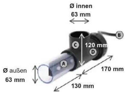
text_image
Ø innen 63 mm 120 mm 170 mm 130 mm Ø außen 63 mmELEKTRONIKGEHÄUSE
natural_image
Four black metal bracket clips with screws attached, arranged in a 2x2 grid (no text or symbols)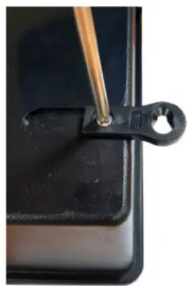
natural_image
Close-up of a black plastic clip with a wooden tool inserted, no visible text or symbols
natural_image
Black rectangular electronic device with four black metal clips and green mounting holes (no text or symbols visible)natural_image
Abstract geometric logo with stylized letter H inside a circular frame (no text or symbols)HAYWARD®
natural_image
Exterior view of a modern industrial air purifier unit with digital display and control buttons (no readable text or symbols)
text_image
CE iAquaRite LT
GEBRUIKERSHANDLEIDING
BEWAAR DEZE GEBRUIKERSHANDLEIDING OM HEM LATER TE KUNNEN RAADPLEGEN
HAYWARD POOL EUROPE - 1070 Allée des Chênes - CS 20054 Saint Vulbas - 01154 Lagnieu Cedex - Frankrijk
OM UW PRODUCT IN ONZE DATABANK TE REGISTREREN, GAAT U NAAR:
www.hayward.fr/en/services/register-your-product

natural_image
Four black metal bracket clips with screws attached, arranged in a 2x2 grid (no text or symbols visible)
natural_image
Close-up of a black plastic clip holding a small hole, with a wooden tool inserted (no text or symbols visible)
natural_image
Black rectangular object with four metallic clips attached, no visible text or symbolstext_image
Technical diagram of a water heater system with labeled components and connectionstext_image
6 Kal. pH Buffer (2pt) Manu. (1pt) Reset cal OK pH:Offset Current measurement 7.2 | pH Target measurement 7.2 | pH Fine adjustment Come adjustment OK Cancel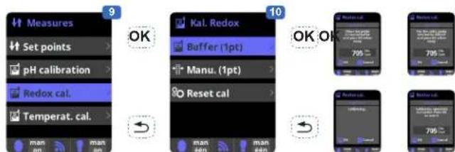
text_image
Measures Set points pH calibration Redox cal. Temperat. cal. 9 OK 10 Kal. Redox Buffer (1pt) Manu. (1pt) Reset cal 705 OK OK 705 705 705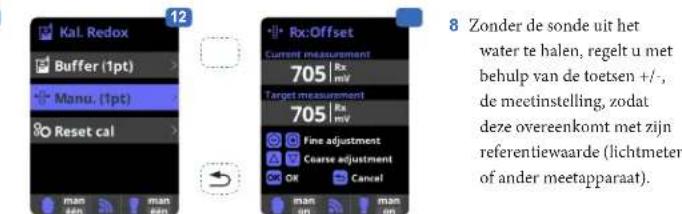
natural_image
Abstract geometric logo with stylized letter H inside a circular frame (no text or symbols)HAYWARD®

natural_image
Exterior view of a modern industrial air purifier unit with digital display and control buttons (no readable text or symbols)
text_image
CE iAquaRite LT
MANUALE D'USO
CONSERVARE IL PRESENTE MANUALE PER FUTURA CONSULTAZIONE
natural_image
Close-up of a black electronic device panel with labeled buttons (A–F) and a cable, no readable text or symbols beyond component labels.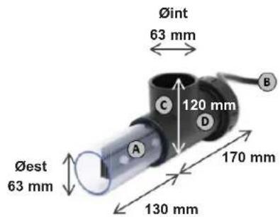
text_image
Øint 63 mm 120 mm 170 mm Øest 63 mm 130 mmSCATOLA ELETTRONICA
natural_image
Four black metal bracket clips with screws, arranged in a 2x2 grid (no text or symbols)
natural_image
Close-up of a black plastic clip with a wooden stick attached, no visible text or symbols
natural_image
Black rectangular object with four side handles and small green circular markers, no visible text or symbols.All HAYWARD products are covered for manufacturing defects or material defects for a warranty period of 2 years as of date of purchases. Any warranty claim should be accompanied by evidence of purchase, indicating date of purchase. We would therefore advise you to keep your invoice.
The HAYWARD warranty is limited to repair or replacement, as chosen by HAYWARD, of the faulty products, provided that they have been subjected to normal use, in compliance with the guidelines given in their user guides, provided that the products have not been altered in any way, and provided that they have been used exclusively with HAYWARD parts and components. The warranty does not cover damage due to frost and to chemicals. Any other costs (transport, labour, etc.) are excluded from the warranty.
HAYWARD may not be held liable for any direct or indirect damage resulting from incorrect installation, incorrect connection, or incorrect operation of a product.
In order to claim on a warranty and in order to request repair or replacement of an article, please ask your dealer.
No equipment returned to our factory will be accepted without our prior written approval.
Wearing parts are not covered by the warranty.
Wear parts: gasket and cell plate coating.