
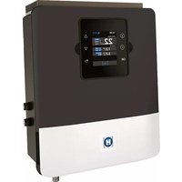
AquaRite UV LS - Water pump HAYWARD - Free user manual and instructions
Find the device manual for free AquaRite UV LS HAYWARD in PDF.
| Product Type | Pool treatment system with electrolysis and UV |
| Brand | Hayward |
| Model | AquaRite UV LS |
| Power Supply | 210-230 V~ 50 Hz, 30 mA RCD protection and 16 A circuit breaker |
| Electrolysis Cell | Titanium, lifespan 8,000 hours |
| UV Lamps | 2 x 55 W, lifespan 8,000 hours |
| Chlorine Production | Adjustable from 0 to 100% |
| Recommended Salt Concentration | 1.5 g/l (low salinity model) or 3 g/l (standard) |
| pH Regulation | Automatic with dosing pump, adjustable setpoint (default 7.2) |
| Redox Control | Optional, adjustable setpoint (default 700 mV) |
| Free Chlorine Measurement | Amperometric or membrane probe, monthly calibration |
| Temperature Probe | Optional, enables Smart and Heating modes |
| Filtration Management | Modes: Manual, Automatic, Smart, Heating, Intelligent |
| Lighting | 12 VAC, 50 W max, programmable with color LED projector |
| Auxiliary Relays | 4 configurable relays (AUX1 to AUX4) |
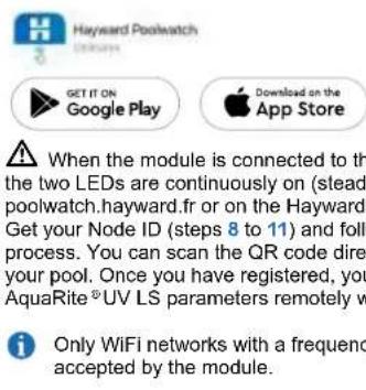
| Connectivity | WiFi or Ethernet module (2.4 GHz), Hayward PoolWatch app |
| Probe Maintenance | Monthly cleaning, lifespan 1 year (6-month warranty) |
| Cell Maintenance | Periodic cleaning, descaling if necessary |
| Wear Parts | Titanium cell, UV lamp, seals, Santoprene tube, probes |
| Warranty | 3 years (excluding wear parts) |
Frequently Asked Questions - AquaRite UV LS HAYWARD
User questions about AquaRite UV LS HAYWARD
0 question about this device. Answer the ones you know or ask your own.
Ask a new question about this device
Download the instructions for your Water pump in PDF format for free! Find your manual AquaRite UV LS - HAYWARD and take your electronic device back in hand. On this page are published all the documents necessary for the use of your device. AquaRite UV LS by HAYWARD.
USER MANUAL AquaRite UV LS HAYWARD
natural_image
Abstract geometric logo with stylized letter H inside a circular frame (no text or symbols)HAYWARD®
natural_image
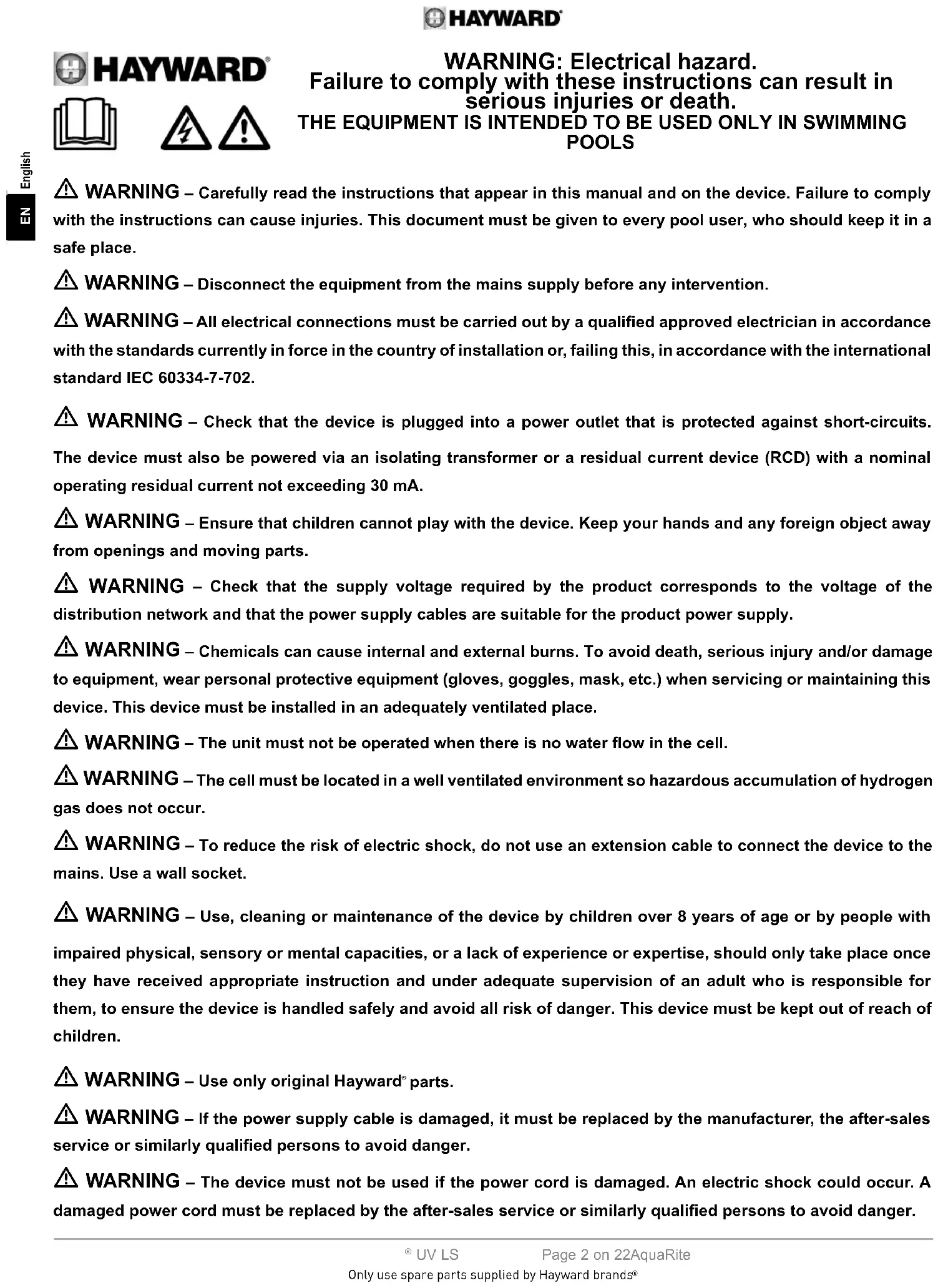
Exterior view of a black electrochemical device labeled '22 g/mL electrolysis Unit 2' and its side-mounted sensor assembly (no readable text beyond labels)AquaRite® UV Low Salinity
CE EHC UK CA

natural_image
Two simple line icons: an open book with an information symbol, and an open book with a closed section (no text or symbols present)GUIDE DE L'UTILISATEUR OWNER'S MANUAL MANUAL DEL USUARIO MANUAL DO UTILIZADOR ANWENDERHANDBUCH GEBRUIKERSHANDLEIDING MANUALE D'USO

natural_image
Abstract geometric logo with stylized letter H inside a circular gradient (no text or symbols)HAYWARD®
natural_image
Exterior view of a black industrial control unit with digital display and mechanical component (no readable text or symbols)CE EHC UK CA

natural_image
Two simple line icons: an open map with an information symbol and an open book, both without any text or symbols.AquaRite® UV LS
GUIDE DE L'UTILISATEUR
CONSERVEZ CE MANUEL POUR UNE CONSULTATION ULTÉRIEURE

HAYWARD®


3b. Installation murale
natural_image
Technical diagram of a heat exchanger or radiator assembly with a bracket and mounting bracket (no text or symbols)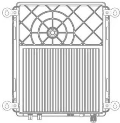
natural_image
Technical line drawing of a mechanical or electrical enclosure with grid pattern and ventilation slots (no text or symbols)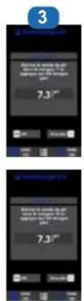

line
| mA | ppm Cl2 | | --- | ------- | | 0 | 0 | | 4 | 0 | | 12 | 5 | | 20 | 10 |
natural_image
Close-up of a blue printed circuit board with visible components and a magnified inset showing internal components (no text or symbols)9. CONDITIONS DE GARANTIE
ET EXCLUSIONS POUR LES PAYS DE L'UNION EUROPÉENNE
natural_image
Abstract geometric logo with stylized letter H inside a circular frame (no text or symbols)HAYWARD®
English
EN

natural_image
Exterior view of a black industrial control unit with digital display and mechanical component (no readable text or symbols)CE EHC UK CA

natural_image
Two simple line icons: a folded map with an information symbol and an open book, both without any text or symbols.AquaRite® UV LS
OWNER'S MANUAL
PLEASE KEEP THIS MANUAL FOR FUTURE REFERENCE

HAYWARD®


WARNING: Electrical hazard.
Failure to comply with these instructions can result in serious injuries or death.
THE EQUIPMENT IS INTENDED TO BE USED ONLY IN SWIMMING POOLS
⚠ WARNING – Carefully read the instructions that appear in this manual and on the device. Failure to comply with the instructions can cause injuries. This document must be given to every pool user, who should keep it in a safe place.
⚠ WARNING – Disconnect the equipment from the mains supply before any intervention.
⚠ WARNING – All electrical connections must be carried out by a qualified approved electrician in accordance with the standards currently in force in the country of installation or, failing this, in accordance with the international standard IEC 60334-7-702.
⚠ WARNING – Check that the device is plugged into a power outlet that is protected against short-circuits. The device must also be powered via an isolating transformer or a residual current device (RCD) with a nominal operating residual current not exceeding 30 mA.
⚠ WARNING – Ensure that children cannot play with the device. Keep your hands and any foreign object away from openings and moving parts.
⚠ WARNING – Check that the supply voltage required by the product corresponds to the voltage of the distribution network and that the power supply cables are suitable for the product power supply.
⚠ WARNING – Chemicals can cause internal and external burns. To avoid death, serious injury and/or damage to equipment, wear personal protective equipment (gloves, goggles, mask, etc.) when servicing or maintaining this device. This device must be installed in an adequately ventilated place.
⚠ WARNING – The unit must not be operated when there is no water flow in the cell.
⚠ WARNING – The cell must be located in a well ventilated environment so hazardous accumulation of hydrogen gas does not occur.
⚠ WARNING – To reduce the risk of electric shock, do not use an extension cable to connect the device to the mains. Use a wall socket.
⚠ WARNING – Use, cleaning or maintenance of the device by children over 8 years of age or by people with impaired physical, sensory or mental capacities, or a lack of experience or expertise, should only take place once they have received appropriate instruction and under adequate supervision of an adult who is responsible for them, to ensure the device is handled safely and avoid all risk of danger. This device must be kept out of reach of children.
⚠ WARNING – Use only original Hayward® parts.
⚠ WARNING – If the power supply cable is damaged, it must be replaced by the manufacturer, the after-sales service or similarly qualified persons to avoid danger.
⚠ WARNING – The device must not be used if the power cord is damaged. An electric shock could occur. A damaged power cord must be replaced by the after-sales service or similarly qualified persons to avoid danger.
INDEX
1. General
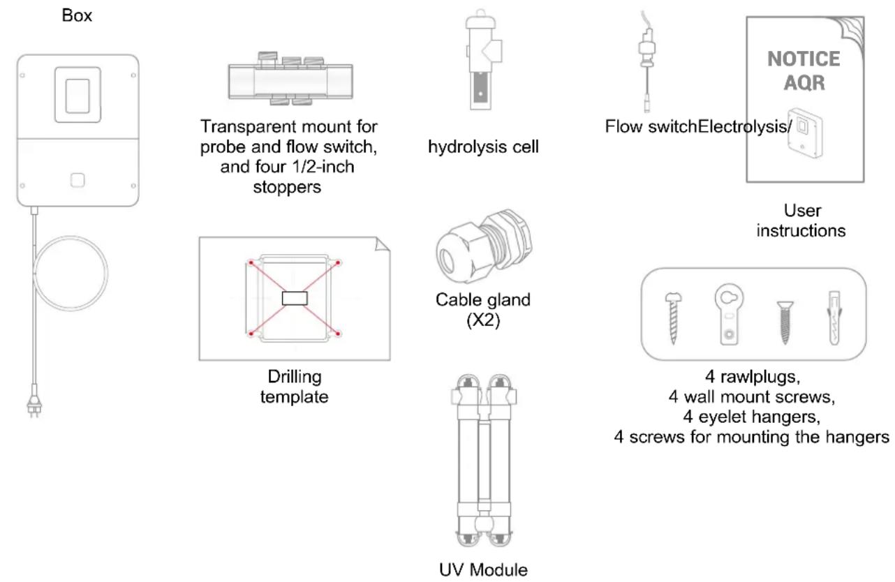
2. Pack contents
3. Installation
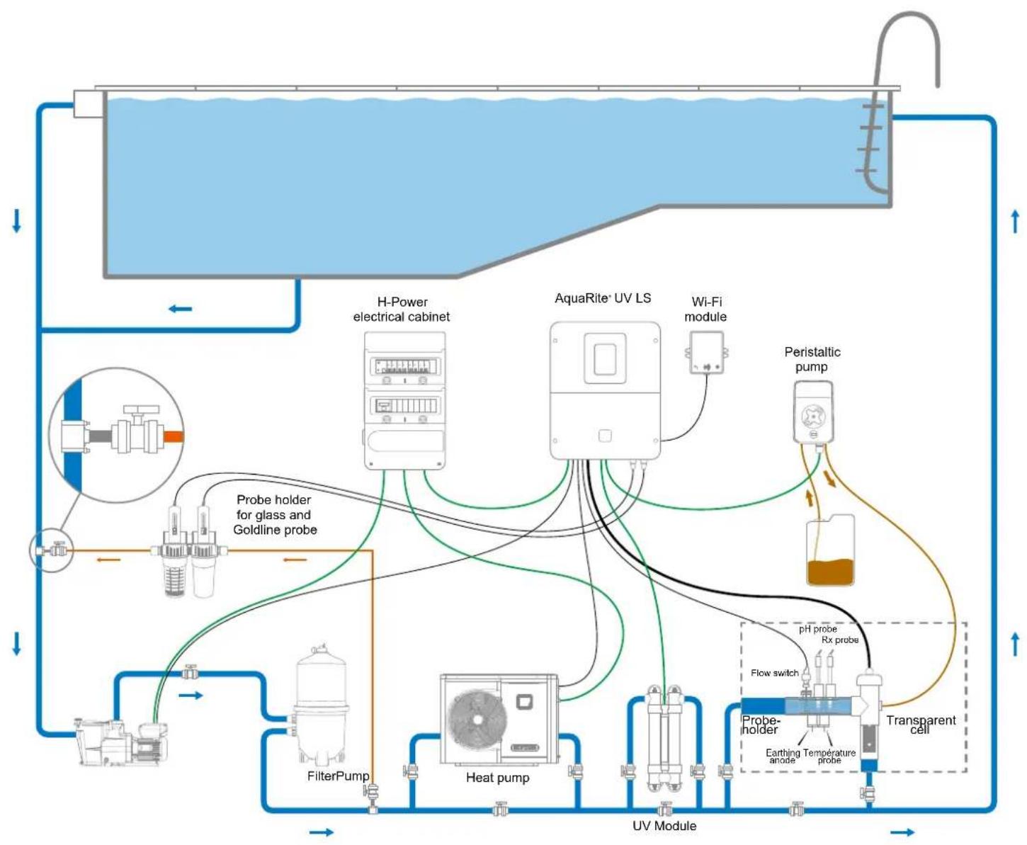
3a. Diagram of overall installation
3b. Wall-mounted installation
3c. Installation and connection of the electronic circuit boards
3d. Cabling the unit
3e. Installation of the cell and the mechanical flow switch
4. Prerequisites for starting up the hydrolysis
5.Operation
5a. View and description of the home screen
5b. Commissioning of the device
5c. Settings
5d. Hydrolysis menu
5e. Installing and configuring the ultraviolet module
5f. Filtration control
5g. Power supply and control for the lighting
5h. Control of auxiliary relays
6. Connecting and configuring peripherals
6a. Installing and starting up the pH option
6b. Installing and starting up the ORP option
6c. Installing and starting up the temperature probe
6d. Installing and starting up a heat pump
6e. Installing and starting up the free chlorine option (amperometric sensor)
6f. Installing and starting up the free chlorine option (membrane sensor)
6g. Installing the WiFi or Ethernet module
6h. Installing and starting up a variable-speed pump
7. Servicing
8. Troubleshooting Guide
9. Warranty conditions and exclusions for European union countries
10. Environmental information
1. GENERAL
The AquaRite ® UV LS is a pool treatment system.
It is an effective water treatment method for your pool that uses electrolysis and hydrolysis of salt water. To operate, the salt chlorinator requires a low salt concentration (sodium chloride) in the pool water. The AquaRite® UV LS automatically disinfects your pool by converting salt into free chlorine, which destroys bacteria and algae present in the water. The UV module is composed of two 55 W lamps. The UV rays counteract the development of algae, deactivate bacteria, viruses and microorganisms, and eliminate chloramines. The chlorine recombines into sodium chloride. This permanent cycle means you do not need to treat your pool manually.
The AquaRite ® UV LS is the healthiest and best-performing water treatment option for all residential pools.
The quantity of chlorine required to treat a pool correctly varies depending on the number of swimmers, precipitation levels, the number of hours of filtration, the temperature and cleanliness of the water, etc.
NOTE: Before installing this product on the filtration system of a pool or spa with an adjacent natural stone terrace or deck, consult a qualified installer who will advise you on the type, installation, sealant (if any) and maintenance of stone that can be laid around a saline pool.
2. PACK CONTENTS
3. INSTALLATION
3a. Diagram of overall installation
flowchart
graph TD
    A["UV Module"] --> B["H-Power electrical cabinet"]
    A --> C["AquaRite UV LS"]
    A --> D["Peristaltic pump"]
    A --> E["Probe holder for glass and Goldline probe"]
    A --> F["FilterPump"]
    A --> G["Heat pump"]
    A --> H["Probe-holder"]
    A --> I["Transparent cell"]
    B --> J["AquaiRite UV LS"]
    C --> K["AquaiRite UV LS"]
    D --> L["Pump"]
    E --> M["Pump"]
    F --> N["Pump"]
    G --> O["Pump"]
    H --> P["Pump"]
    I --> Q["Pump"]
    J --> R["Flow switch"]
    K --> S["Flow switch"]
    L --> T["Flow switch"]
    M --> U["Flow switch"]
    N --> V["Flow switch"]
    O --> W["Flow switch"]
    P --> X["Flow switch"]
    Q --> Y["Flow switch"]
    R --> Z["Probe probe Rx probe"]
    S --> AA["Probe probe Rx probe"]
    T --> AB["Probe probe Rx probe"]
    U --> AC["Probe probe Rx probe"]
    V --> AD["Probe probe Rx probe"]
    W --> AE["Probe probe Rx probe"]
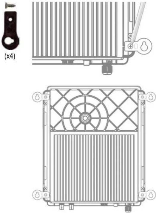
3b. Wall-mounted installation
Mount the unit on the wall. The unit must be installed in the equipment room (dry, mild conditions, ventilated). Caution, acid vapours can cause irreversible damage to your device. Position the treatment product tanks accordingly.
Unplug the pool filter pump before you begin the installation. The installation must be performed in compliance with the regulations in effect in the country of installation.
The AquaRite® UV LS must be fitted a minimum horizontal distance of 3.5 m (or more, if required by local regulations) from the pool, within 1 m of a protected outlet and within 4.5 m of the planned cell location. The unit must be placed vertically on a flat surface, with the cables downwards. As this box is also used to evacuate heat (heat dissipation from internal components), it is important that the four sides of the box remain unobstructed. Do not install the AquaRite® UV LS behind a panel or in an enclosed space.
Before installing the unit in the intended location, check that the power cord can reach the protected outlet and that the cell cable can reach the intended cell location.
All the metal components of the swimming pool can be connected to the same earth as per local regulations.
3c. Installation and connection of the electronic circuit boards
Connect the AquaRite ® UV LS to a permanent power outlet.
⚠️: This circuit must be protected by a residual current device (RCD) (residual current: 30 mA max.) and a 16A time-delay circuit-breaker.
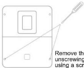
Remove the white lid by unscrewing the 4 screws using a screwdriver.
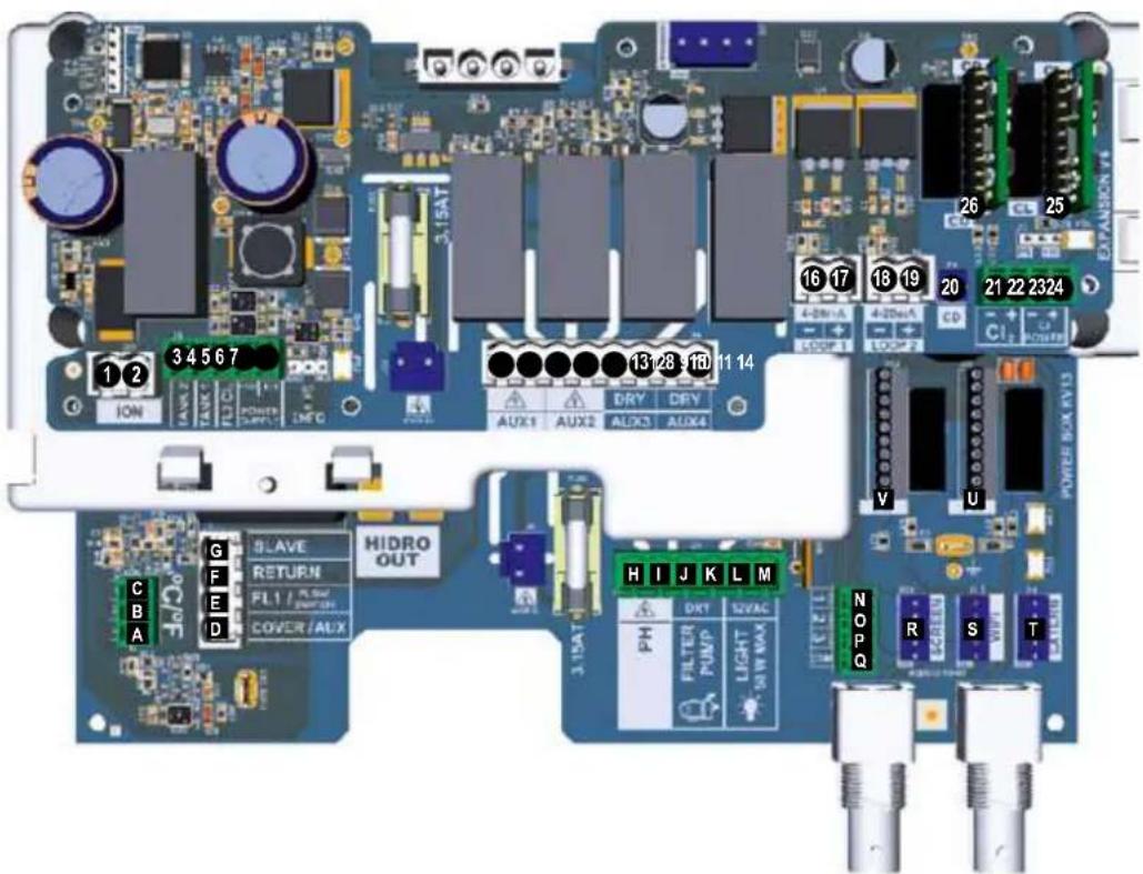
Connection of inputs:
| Circuit board | Name Description Terminals Type of input / output | |||
| Main °C Temperature probe (optional) A-B-C Red, yellow, black | ||||
| Main | COVER / AUX | Pool shutter position sensor | D-F | Dry contact |
| Main | FL1 / FLOW SWITCH | Mechanical flow switch E-F Non-polarised dry contact | ||
| Main | SLAVE | Terminal for master or slave box | G-F | Dry contact |
| Main | PH | Peristaltic or electromagnetic injection pump | H-I | Output: Voltage 230 VAC 5A max |
| Main | FILTER PUMP | Control of filtration pump | J-K | Dry contact |
| Main | LIGHT 50W | Control and power supply for lighting | L-M | Output: Voltage 12 VAC 50W max |
| Main | VARIABLE SPEED PUMP | Control of variable speed pump | N-O-P-Q | Dry contactV1 - V2 - V3 - Common |
| Main SCREEN Remote screen (optional) R | Modbus RS465From top to bottom: red/free/yellow/green/black | |||
| Main | WIFI | WiFi or Ethernet module (optional) | S | Modbus RS465From top to bottom: red/free/yellow/green/black |
| Main | EXTERN | Standard communication connector | T | Modbus RS465From top to bottom: red/free/yellow/green/black |
| Main | PH | pH Connection chip (optional), with markings and LED on the left | U | 5 VDC |
| Main | RX | ORP Connection chip (optional) with markings and LED on the left | V | 5 VDC |
| Extension | ION | Connector for power supply to copper electrode (not provided) | ||
| Extension | TANK1 | Empty container sensor 1 | 3-6 | Dry contact |
| Extension | TANK2 | Empty container sensor 2 | 4-6 | Dry contact |
| Extension | FL2 CL2 | Flow switch for free chlorine sensor | 5-6-7for amperometric5-6for membrane | Black - brown - blueBlack - red |
| Extension | AUX1 | UV Module | 8-9 | Output: Voltage 230 VAC 5A max |
| Extension | AUX2 | Control and power supply by relay | 10-11 | Output: Voltage 230 VAC 5A max |
| Extension | AUX3 | Control by relay | 12-13 | Dry contact |
| Extension | AUX4 | Control of heat pump (temperature option) or control by relay | 14-15 | Dry contact |
| Extension | 4-20mA LOOP1 | Reading from free chlorine sensor equipped with membrane | 16-17 | +: green (+12 VAC) /-: yellow (4-20mA) |
| Extension | 4-20mA LOOP2 | Reading from 4-20 mA probe | 18-19 | 12 VAC 4-20mA |
| Extension | CD | Connection of conductivity probe | 20 | |
| Extension | CL2 | Connection of amperometric free chlorine sensor | 21-22 | |
| Extension | CL POWER | 23-24 | ||
| Extension | CL | CL Connection chip (optional) with markings and LED on the left | 25 | 5 VDC |
| Extension | CD | CD Connection chip (optional) with markings and LED on the left | 26 | 5 VDC |
3d. Cabling the box
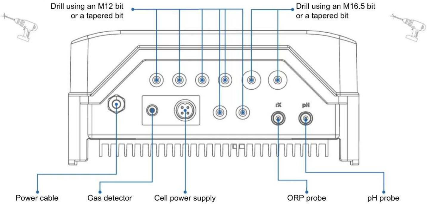
6 inputs for equipment cables WiFi / Ethernet module
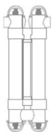
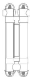
3e. Installation of the cell and the mechanical flow switch
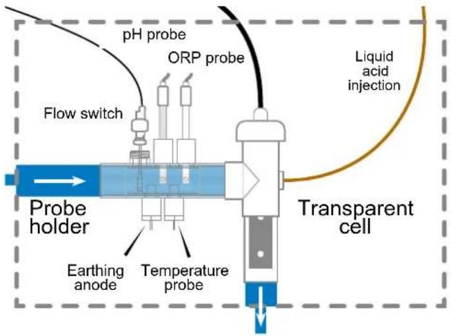
flowchart
graph TD
    A["Flow switch"] --> B["Probe holder"]
    B --> C["Earthing anode"]
    B --> D["Temperature probe"]
    B --> E["ORP probe"]
    E --> F["Liquid acid injection"]
    G["pH probe"] --> B
    H["Transparent cell"] --> B
    style A fill:#f9f,stroke:#333
    style B fill:#bbf,stroke:#333
    style C fill:#dfd,stroke:#333
    style D fill:#dfd,stroke:#333
    style E fill:#dfd,stroke:#333
    style F fill:#dfd,stroke:#333
    style G fill:#fff,stroke:#333
    style H fill:#fff,stroke:#333
Installation and connection of the cell (see diagram):
• Install the cell mount vertically (if it is installed horizontally, please contact your installer for an update of the unit programming).
• Install the cell in a bypass.
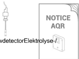
- Connect the power supply cable to the 4-pin terminal on the underside of the box, and the gas detector to the RCA jack.
Installation and connection of the mechanical flow switch:
• Install the flow switch mount before the cell and on the bypass.
- Unscrew the white protective cover of the mechanical flow switch.
- Screw the flow switch onto the 3/4" male thread.
- Connect the red and black cables to the electronic circuit board terminals E and F.
4. PREREQUISITES FOR STARTING UP THE HYDROLYSIS
Preparing the pool water
To prepare the pool water to enable the AquaRite ® UV LS to function, its chemical composition must be balanced and salt added. This must be done BEFORE turning on the AquaRite ® UV LS. Certain adjustments to the chemical balance of the pool can take several hours. The procedure must therefore be started well before the AquaRite ® UV LS is turned on.
Adding salt: Add the salt several hours or, if possible, a day before turning on the Compass Salt Water salt chlorinator. Ensure that the recommended amount of salt is used. Measure the salt content 6 to 8 hours after adding the salt to the swimming pool.
NOTE: If the water in the pool is not fresh and/or if it is liable to contain dissolved metals, use a metal remover, according to the manufacturer's instructions.
If your water has previously been treated with a product other than chlorine (bromine, hydrogen peroxide, PHMB, etc.), neutralize this product or replace all the water in the pool.
Salt concentration
Use the following table to determine the quantity of salt (in kg) needed to reach the recommended concentrations. Use the formulae below if you do not know the volume of your swimming pool.
| m3(pool dimensions, in m) | |
| Rectangular | Length x width x average depth |
| Round | Diameter x diameter x average depth x 0.785 |
| Oval | Length x width x average depth x 0.893 |
The salt concentration depends on the unit model. Reference: 3 g/l for standard salinity units, and 1.5 g/l for low salinity units (displayed in % on the screen).
A low salt level reduces the efficiency of the AquaRite ® UV LS and causes a reduction in disinfectant production. The unit will display the message “Low” on the screen. There is no risk of premature deterioration of the box and cell.
There is no risk of damage to the box or the cell due to a high salt concentration. The effect of this is simply that it gives your pool water a salty taste.
As the salt in your pool is constantly being recycled, the loss of salt during the season is minimal. The salt concentration is primarily reduced when the water level must be topped up due to splashing or backwashing, or when rain adds fresh water to the pool. Salt is not lost through evaporation.
Type of salt to use
Use only salt that complies with standard EN 16401 and is intended for salt chlorinators. Use only sodium chloride (NaCl) that is more than 99% pure. Do not use food-grade salt, iodized salt, salt containing yellow prussiate of soda or salt containing anti-caking additives.
How to add or remove salt
For new pools, let the plaster dry for ten to fourteen days before adding salt. Start up the filtration pump, then add salt directly into the intake side of the pool. Make the water circulate to speed up the dissolution process. Do not allow salt to accumulate at the bottom of the pool. Run the filtration pump for 24 hours, opening the main drain valve fully to allow the salt to dissolve evenly throughout the pool.
The only way to lower the salt concentration is to partially empty the pool and refill it with fresh water.
Always check the stabilizer (cyanuric acid) when checking the salt concentration. The corresponding concentrations tend to decrease together. Refer to the following table to determine the quantity of stabilizer required in order to achieve a concentration of 25 ppm. Add stabilizer only if necessary.
Do not add stabilizer to indoor pools.
Quantity of stabilizer (CYANURIC ACID in kg) required for 25 ppm
| Current salt concentration (ppm) | Volume of water in the pool in m3 | ||||||||||||||||
| 30 37.5 | 45 52.5 | 60 67.5 | 75 82.5 | 90 97.5 | 105 112.5 | 120 127.5 | 135 142.5 | 150 | |||||||||
| 0 ppm | 0.75 | 0.94 | 1.13 | 1.34 | 1.53 | 1.69 | 1.91 | 2.09 | 2.28 | 2.47 | 2.66 | 2.84 | 3.03 | 3.22 | 3.41 | 3.59 | 3.75 |
| 10 ppm | 0.45 | 0.56 | 0.68 | 0.81 | 0.92 | 1.01 | 1.14 | 1.26 | 1.37 | 1.48 | 1.59 | 1.71 | 1.82 | 1.93 | 2.04 | 2.16 | 2.25 |
| 20 ppm | 0.15 | 0.19 | 0.23 | 0.27 | 0.31 | 0.34 | 0.38 | 0.42 | 0.46 | 0.49 | 0.53 | 0.57 | 0.61 | 0.64 | 0.68 | 0.72 | 0.75 |
| 25 ppm | 0 | 0 | 0 | 0 | 0 | 0 | 0 | 0 | 0 | 0 | 0 | 0 | 0 | 0 | 0 | 0 | 0 |
Chemical water balance
The water must be balanced manually BEFORE the device is started up.
The following table summarizes the concentrations recommended by Hayward. Your water should be checked regularly to maintain these concentrations and minimize surface corrosion or deterioration.
CHEMISTRY RECOMMENDED CONCENTRATIONS
| Salt 1.5 g/l | |
| Free chlorine 0.5 to 2.5 | ppm |
| pH 7.2 to 7.6 | |
| Cyanuric acid (Stabilizer) | 20 to 30 ppm max.(Add stabilizer only if necessary)0 ppm in indoor pool |
| Total alkalinity 80 to 12 | 0 ppm |
| Water hardness 200 to | 300 ppm |
| Metals 0 ppm | |
| Langelier index -0.2 to | 0.2 (preferably 0) |
5. OPERATION
The device is designed to be connected to a protected outlet at all times. The AquaRite ® UV LS must not be disconnected unless the pool equipment is undergoing maintenance or the pool is to be closed (wintering).
If the water parameters are within the recommended ranges, the device can be started up.
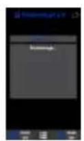
5a. View and description of the home screen
5b. Commissioning of the device

Choose your preferred language and confirm using the OK button.
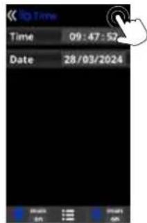
Confirm the current time and date using the OK button.
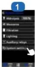
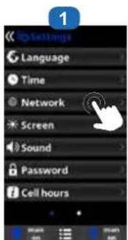
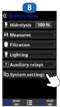
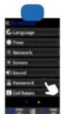
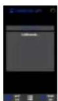
5c. Settings
EN English
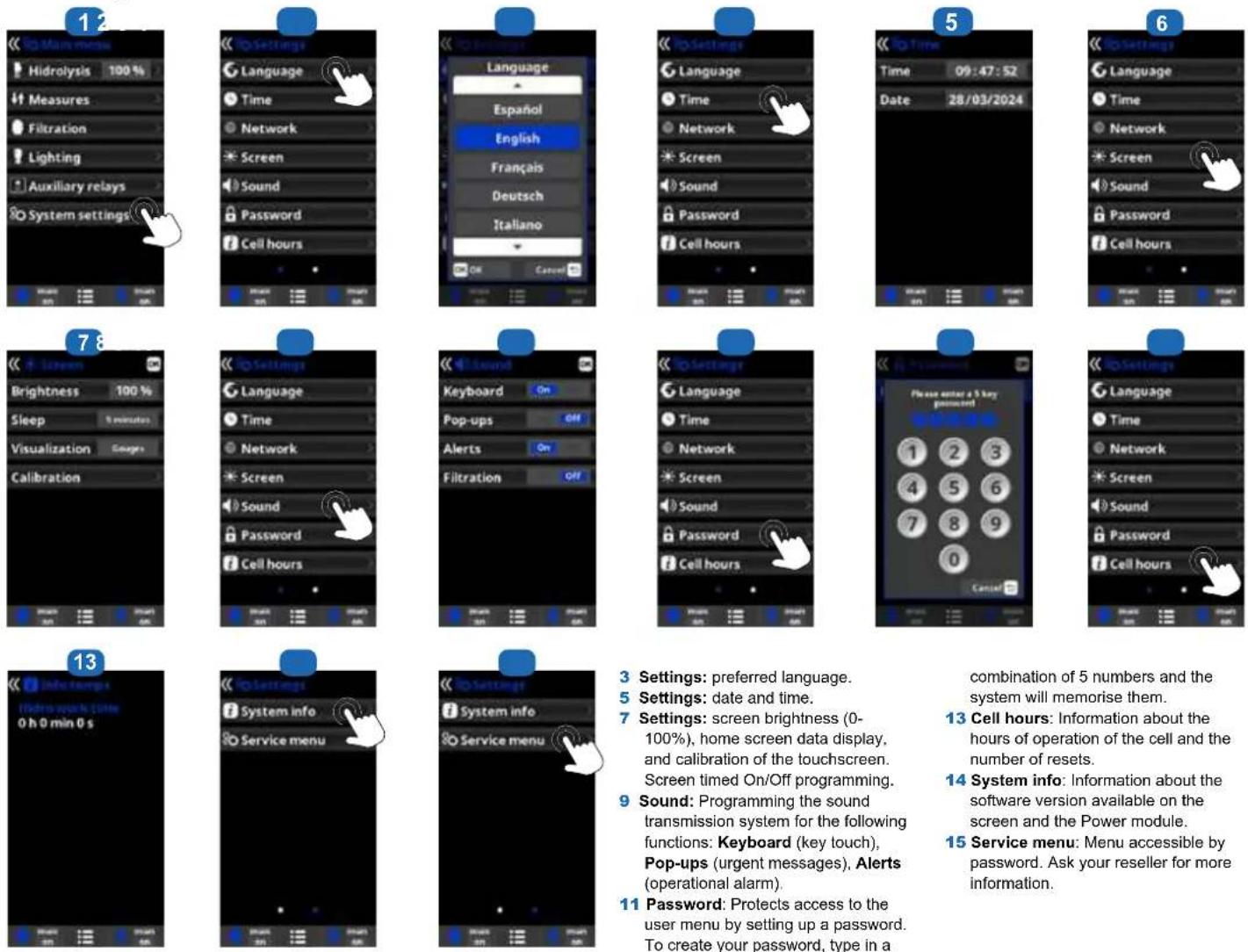
3 Settings: preferred language.
5 Settings: date and time.
7 Settings: screen brightness (0-100%), home screen data display, and calibration of the touchscreen. Screen timed On/Off programming.
9 Sound: Programming the sound transmission system for the following functions: Keyboard (key touch), Pop-ups (urgent messages), Alerts (operational alarm).
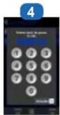
11 Password: Protects access to the user menu by setting up a password. To create your password, type in a
combination of 5 numbers and the system will memorise them.
13 Cell hours: Information about the hours of operation of the cell and the number of resets.
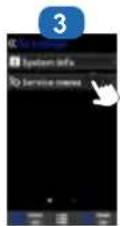
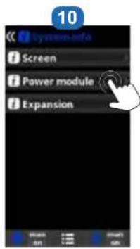
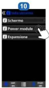
14 System info: Information about the software version available on the screen and the Power module.
15 Service menu: Menu accessible by password. Ask your reseller for more information.
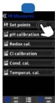
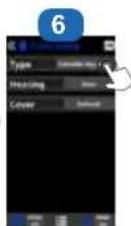
5d. Hydrolysis menu
The hydrolysis has not reached the required production rate.

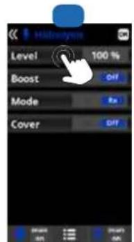
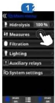
1 Hydrolysis: Programming of hydrolysis functions.
2 Level: Chlorine production (%) required.
3 Cover: Closed cover safety activation.
Reduction: % of chlorine production when the cover is closed (20% by default).
4 Boost (Super Chlorination): Press On.
5 Shock validation: Continuous chlorine production for 24 hours (the production level must be configured to the maximum). Request for activation with or without ORP control.
5e. Installing and configuring the ultraviolet module
⚠️ Make sure you have installed the UV module on a bypass and upstream of the cell.
The UV function is preset to ON. It turns on when the filtration is running.
Open the lid and connect the UV module to AUX1 (see paragraph 3C).
Configuring the UV module:
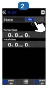
1 Go into the UV menu to see the state of the lamp.
2 Go into the UV menu to see the state of the lamp.
The partial time corresponds to the length of the last period of operation of the UV lamp.
The total time corresponds to the cumulative total length of all lamp operating periods.
It is recommended that the quartz should be cleaned every year to optimise operation of the UV lamp.
5f. Filtration control
The electrolysis and measurements will not activate unless the filtration is running.
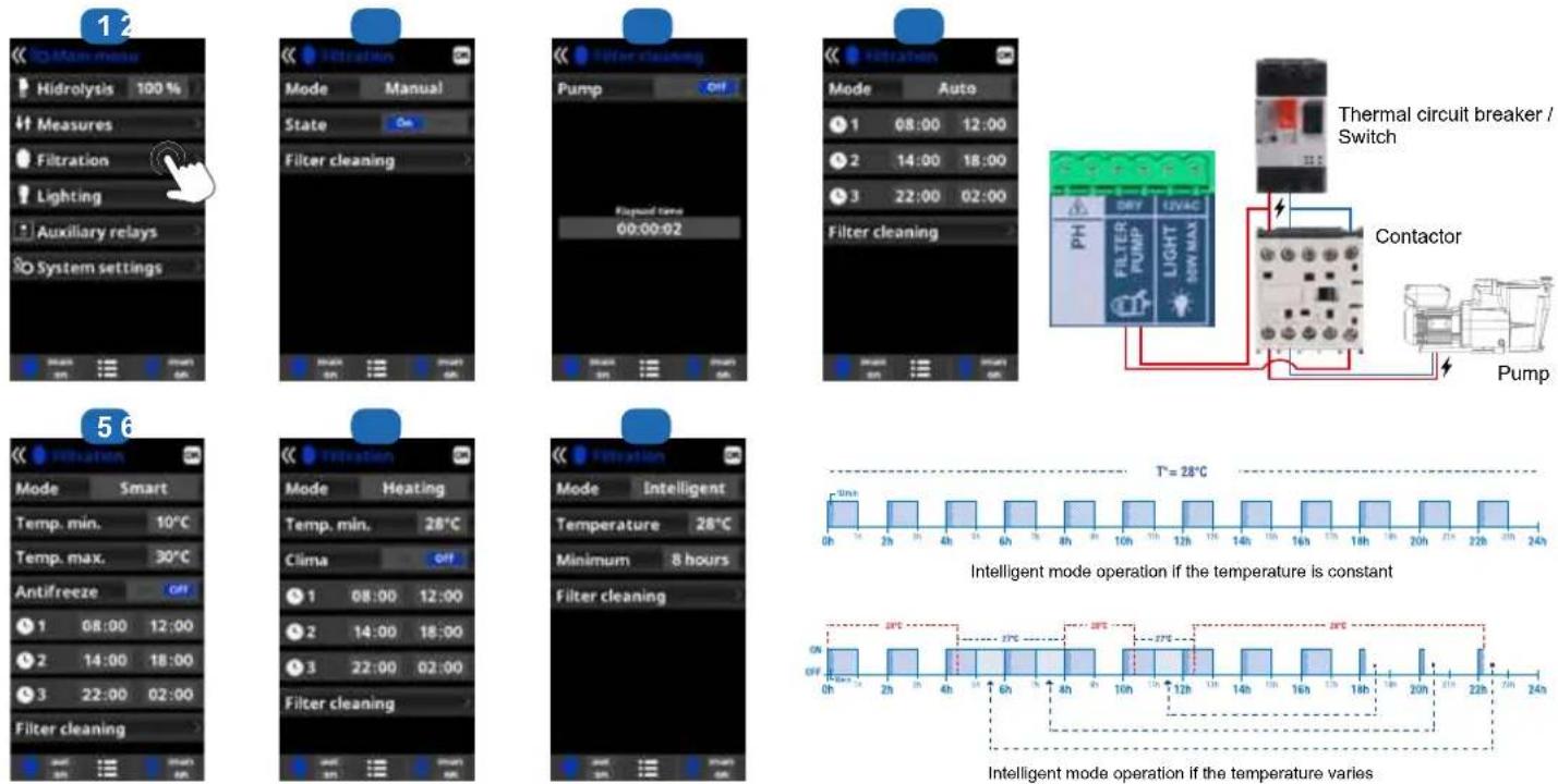
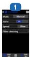
1 Filtration modes.
2 Manual: Allows the filtration process to be turned on and off manually.
3 Filter cleaning: This mode is used to backwash the filter.
4 Automatic: In this mode, filtration is turned on and off according to the start and end times. These time slots must be programmed within a single day (midnight to midnight).
4 Smart: mode may be activated if and only if the temperature probe has been activated. This mode is based on the automatic mode, with its three filtration intervals, but the filtration times are adjusted according to the temperature. This is done by setting two temperature parameters: the maximum temperature, above which the filtration times will be determined by the time slots, and the minimum temperature, below which filtration will be reduced to five minutes, the minimum operation period. Between these two temperatures, the filtration times will be staggered linearly. The antifreeze mode can be activated to turn the filtration on if the water temperature falls below 2°C.
5 Heating: mode may be activated if and only if the temperature probe and heat pump are both activated and configured. This mode acts in the same way as the automatic mode, but it can also operate via a relay that controls the temperature. The set point temperature is determined in this menu and the system operates with a hysteresis of one degree (for example: if the set point temperature is 23irc C, the system will start up when the temperature falls below 22irc C and shut down only when it rises above 23irc C).
Heating control OFF: The heating operates only during the configured filtration periods.
Heating control ON: Keeps the filtration on after the filtration period has expired if the temperature is below the set point temperature. When the setpoint temperature is reached, the filtration and heating stop and only resume when the next programming period begins.
6 Intelligent:mode may be activated if and only if the temperature probe and heat pump are both activated and configured. In this mode, the user has two operating parameters: select the required water temperature and the minimum filtration time
(minimum two hours and maximum 24 hours). The filtration will operate for at least ten minutes every two hours to check the temperature. The minimum filtration time selected is divided into twelve sections that are added to these ten minutes.
Example 1: Over twelve hours, the time is divided between the twelve times a day when the filtration starts up to check the temperature.
Example 2:
(12 hours x 60 minutes) / 12 = 60 minutes every two hours. This is the filtration and heating period every two hours. If the programmed filtration period ends and the required temperature has not been reached, the filtration and heating remain on until the required temperature is reached. To minimize the number of hours during which filtration operates each day, this additional time will be deducted from the next filtration periods occurring during the rest of the day. (See the chart below).
5g. Control and power supply for lighting
The unit supplies a voltage of 12 VAC 50W max.
Chlorine production is reduced by a third when the lighting is activated.
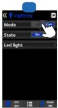
1 Lighting.
2 Manual mode (ON/OFF).
3 Automatic mode: Starts up according to the time slots selected for the lighting. The time slots can be configured with the following frequencies: daily, every 2 days, every 3 days, every 4 days, every 5 days, weekly, every 2 weeks, every 3 weeks, every 4 weeks.
4 LED light: If you are using a coloured LED light, go to the menu to configure it. Colour selection: This menu allows you to change the colours manually and, according to the type of LED light, program the pulse length required to cycle through the colours and programs (by default, 0.5 s, maximum 10 s).
5h. Control of auxiliary relays
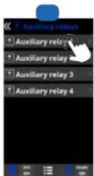
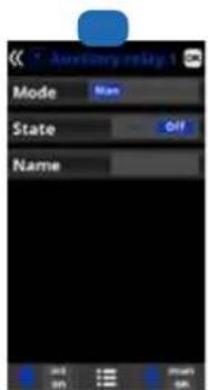
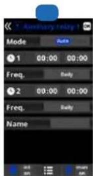
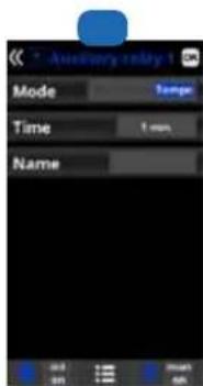
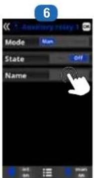
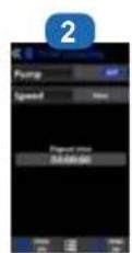
1 Auxiliary relays.
2 A maximum of four additional auxiliary relays (water features, fountains, garden lighting, etc.) can be controlled. This menu displays and allows you to configure the relays that remain available on your equipment.
3 Manual mode (ON/OFF).
4 Automatic mode: Starts up according to the selected time slots. They can be configured with the following frequencies: daily, every 2 days, every 3 days, every 4 days, every 5 days, weekly, every 2 weeks, every 3 weeks, every 4 weeks.
5 Timer mode: An operating time can be programmed in minutes. Each time you press the front panel key associated with the relay, it will be activated for the programmed time. This function is recommended for timing the operation of spa blowers.
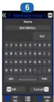
6 Relay name: It is possible to name the auxiliary relays individually according to the associated functions. To confirm, press OK.
6. CONNECTING AND CONFIGURING PERIPHERALS
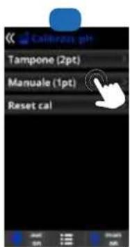
6a. Installing and starting up the pH option
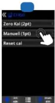
Always begin the calibration procedure with a calibration reset.
1 Open the cover and connect the pH CHIP card to the PH slot (see section 3C). The pH reading and the Measures menu will be displayed automatically, to configure the setpoint and carry out the calibration.
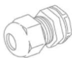
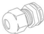
2 Connect the dosing pump to the pH terminal using a cable gland (see section 3C and 3D) and close the cover.
3 Install the probe with its mount in the pipe and connect the probe to the unit (see section 3D).
⚠️ Follow the instructions for the pH pump to inject the liquid.
• The probe has a lifetime of 1 year. We recommend calibrating it every month during the season the pool is in use.
Connecting the pH dosing pump
1 Connect the suction strainer: insert the (transparent) PVC suction tube all the way into the conical connector of the suction strainer, tighten the clamping nut and position the suction strainer in the bottom of the container holding the chemical to be dosed.
2 Connect the suction and delivery tubes: loosen the pump clamping nuts, insert the (transparent) PVC suction tube on the left and the (opaque) PE
delivery tube on the right all the way into the conical connector, and tighten the clamping nut.
3 Connect the injection valve: loosen the nut, insert the (opaque) PE delivery tube all the way into the conical connector, and tighten the clamping nut. Screw the valve on to the mount provided on the cell using Teflon tape.
Operation of pH corrector dosing pump:
The pump starts up depending on the setpoint entered in the menu Measures - Setpoints - acid pH (setpoint < water pH). By default, the maximum dosing time is 120 minutes to avoid acidification of the water (AL3). The proportional method is used for injection: 10 minutes ON (variable depending on the difference between the measured value and the setpoint) + 5 minutes OFF (fixed). Both acid and alkali can be dosed (contact your installer). The pump is equipped with an on/off switch.
⚠ The Santoprene tube of the peristaltic pump has a lifetime of 2 years. We recommend changing it once a year.
Installing and preserving the pH probe:
1 The pH probe is "wet" packed and protected by a plastic cap. The probes must always remain
wet. If the probes are allowed to dry, they will be permanently unusable (not covered by the warranty) and the pH test kit will be ineffective.
2 Remove the pH probe from its protective plastic cap and set the cap aside for later use (wintering or maintenance).
3 Put the probe into the probe holder or double probe holder (depending on the options ordered) and tighten the probe mounts to ensure watertightness.
4 Check that the probes are watertight at startup. Seal with Teflon, if required.
5 After installation, check that the probes are constantly in contact with the pool water. When the filtration pump is not running (even for long periods), the water remaining in the pipes is sufficient to protect the probes.
The sanitization products (acid, etc.) must be injected last on the water return line, after any equipment (heater, cell, etc.). Seal with Teflon.
All types of acid (sulphuric, hydrochloric or a blend) are compatible. We recommend using sulphuric acid.
The use of dry acid such as sodium bisulfate to adjust the pH of the swimming pool is not recommended, especially in arid regions where pool water is subject to significant evaporation and is not commonly diluted with mains water. Dry acid can cause a build-up of by-products that can damage your chlorinator.


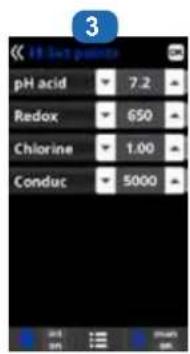
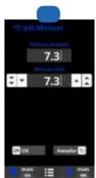
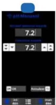
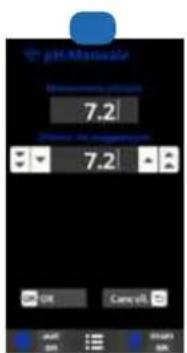
The default value is 7.2.
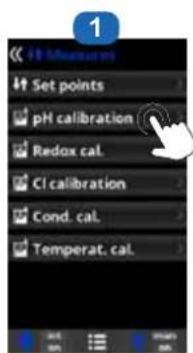
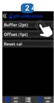
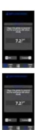
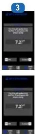
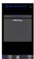
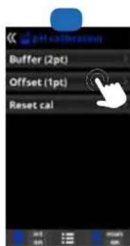

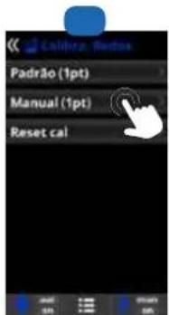
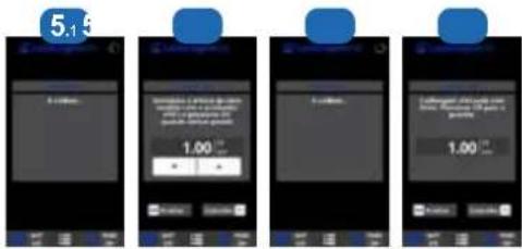
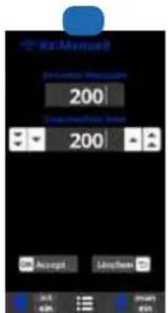
1 pH probe calibration: Recommended once a month during the pool season.
2 Calibration using buffer solutions (buffer solutions pH7 / pH10 / neutral). Follow the instructions that appear on screen 3.
3 Calibration procedure involving 7 steps. 4 Manual calibration: Allows you to calibrate the probes using 1 point (without buffer solution) – recommended only for adjusting small deviations in readings.
5 Without taking the probe out of the water, use the Up/Down arrows to adjust the measurement displayed so that it coincides with the reference value (photometer or other measuring instrument).
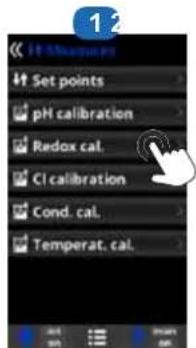
6b. Installing and starting up the ORP option
⚠️ Always begin the calibration procedure with a calibration reset.
1 Open the cover and connect the rX CHIP card to the RX slot (see section 3C). The ORP reading and the Measures menu will be displayed automatically, to configure the setpoint and calibrate the probe.
2 Install the probe with its mount in the pipe, connect the probe to the unit (see section 3D), and close the cover.
The probe has a lifetime of 1 year. We recommend calibrating it every month during the season the pool is in use.
Operation of the ORP module: By default, when the ORP option is connected, the electrolysis cell starts up as soon as the measured ORP value falls below the setpoint.
Installing and preserving the ORP probe:
1 The ORP probe is «wet» packed and protected by a plastic cap. The probes must always remain wet. If the probes are allowed to dry, they will be permanently unusable (not covered by the warranty) and the ORP test kit will be ineffective.
2 Remove the ORP probe from its plastic protective cap and set the cap aside for later use (wintering or maintenance).
3 Put the probe into the probe holder or double probe holder (depending on the options ordered) and tighten the probe mounts to ensure watertightness.
4 Check that the probes are watertight at startup. Seal with Teflon, if required.
5 After installation, check that the probes are constantly in contact with the water in the pool. When the filtration pump is not running (even for long periods), the water remaining in the circuit may be sufficient to protect the probes.
The product (liquid chlorine, etc.) injection device must be installed last on the water return line, after any equipment (heater, cell, etc.). Seal with Teflon.
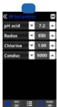
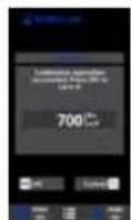
The default value is 700 mV.
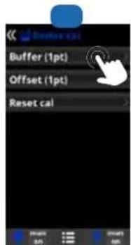

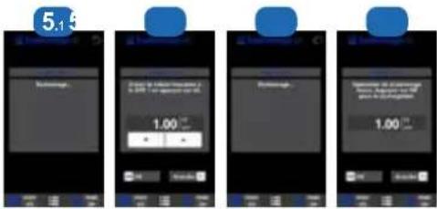
1 ORP probe calibration: Recommended every two months during the pool season.
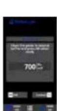
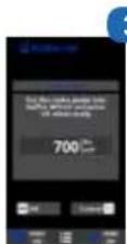
2 Calibration with buffer solutions. With reference solution 465 mV. Follow the instructions that appear on screen 3.
3 Calibration procedure involving 4 steps.
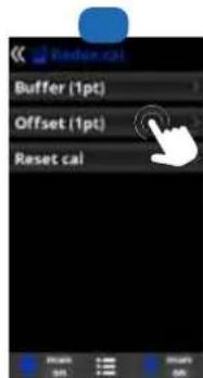
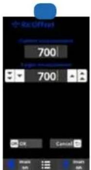
4 Manual calibration: Allows you to calibrate the probes using 1 point (without solution) – recommended only for adjusting small deviations in readings.
5 Without taking the probe out of the water, use the Up/Down arrows to adjust the measurement displayed so that it coincides with the reference value (photometer or other measuring instrument).
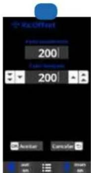
Setting the ORP level
The ORP level tells you the oxidation potential, i.e. the disinfectant capacity of the water.
Setting the ORP set point is the last step in setting the AquaRite ® UV LS.
To find the optimum ORP level for your pool, follow the steps below:
1 Start up the pool filtration system (the salt in the pool must be evenly dissolved).
2 Add chlorine to the swimming pool until it reaches 1 to 1.5 ppm. This level is achieved with approximately 1 to 1.5 g/m³ of water.
The pH level must vary between 7.2 and 7.5.
3 After 30 min. check that the level of free chlorine in the pool (manual DPD1 test kit) is between 0.8 and 1.0 ppm.
4 Look at the ORP value on the screen and enter it as the ORP set point.
5 The next day, check the free chlorine level (manual DPD1 test kit) and the ORP level. Increase / reduce the setting, if required.
Remember to check all your water parameters at regular intervals (2-3 months) (see table Chemical water balance) and adjust the ORP set point according to the steps listed above.
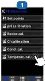
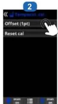
6c. Installing and starting up the temperature probe
⚠️ Always begin the calibration procedure with a calibration reset.
⚠️ Please contact your reseller to configure the temperature probe.
1 Open the cover, connect the temperature probe to the °C terminal using a cable gland (see section 3C and 3D) and close the cover.
2 Configure the temperature probe in the service menu. Follow the procedure shown here and contact your installer.
3 The temperature value appears in the top-right corner of the screen.
1 Temperature probe calibration: Allows you to set the probes to 1 point.
2 Manual calibration.
3 Without taking the probe out of the water, use the Up/Down arrows to adjust the measurement displayed so that it coincides with the reference value.
i Activation of the temperature probe gives access to the Smart filtration mode.


6d. Installing and starting up a heat pump
⚠️ Please contact your reseller for installation and configuration of a heat pump.
1 Open the cover, and plug the heat pump cable into terminal AUX4 using a cable gland (see paragraph 3C and 3D) and close the cover again.


3 Enter the Service menu from the configuration menu.
4 Enter the password (contact your reseller for the password).
5 Enter the Extra settings menu.
6 Select the Heat menu
7 Press Relay config.
8 Keep pressing until you select AUX4.
9 In the Filtration menu, the Heating and Intelligent modes will appear automatically. Please select and configure one of the 2 modes.
i Activation of a heat pump gives access to the Heating and Intelligent filtration modes.
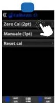
6e. Installing and starting up the free chlorine option (amperometric sensor)
⚠️ Always begin the calibration procedure with a calibration reset.
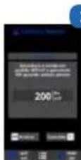
⚠️ We recommend calibrating the free chlorine sensor with a high chlorine level: between 1ppm and 1.2ppm.
1 Open the cover and connect the CL CHIP card to the CL slot (see section 3C). The chlorine reading and the Measures menu will be displayed automatically to configure the setpoint and carry out the calibration.
2 Place the sensor in a bypass, following the sensor instructions.
3 Connect the 3 cables of the floater to the extension circuit board (see section 3C).
4 Connect the 2 cables of the sensor to the extension circuit board (see section 3C).
5 Start sensor calibration.
The flow through the transparent mount must be constant to ensure optimum reading.
The sensor has a lifetime of 1 year. We recommend calibrating it once a month during the season the pool is in use

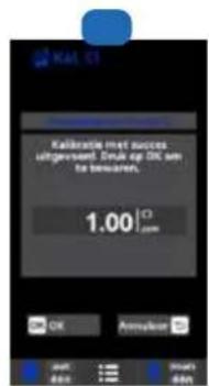
1 Calibration of free chlorine: It is recommended to do this once a month during the season the pool is in use.
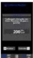
2 Calibration using reference values (DPD1 photometer): Follow the 6-step instructions that appear on the display screen (points 4 to 7).
3 Manual calibration: Open the water intake and wait until the free chlorine value displayed on the unit screen is stable. With the up/down buttons, adjust the value displayed until it coincides with the free chlorine value measured during the DPD1 analysis (in ppm), then press OK.
4 Step 1 of 6 - CL calibration of 1st point (0 ppm): Stop the flow of water through the sensor and wait until the value displayed on the
unit screen drops below 0.10 ppm (between 5 and 60 minutes). Press OK when the value is close to 0.
5 Step 3 of 6 - CL calibration of 2nd point: Open the water intake to a rate of 80-100 litres/h then wait until the free chlorine value is stable (between 5 and 20 minutes). Press OK when the value is stable.
6 Step 5 of 6 - With the up/down buttons, adjust the displayed value until it coincides with the free chlorine concentration measured during the DPD1 analysis (in ppm) then press OK.
7 Step 6 of 6 - If this screen does not appear, repeat the calibration process.

6f. Installing and starting up the free chlorine option (membrane sensor)
⚠️ Always begin the calibration procedure with a calibration reset.
⚠️ Please contact your dealer for configuration of the free chlorine sensor equipped with a membrane.
We recommend calibrating the free chlorine sensor with a high chlorine level: between 1ppm and 1.2ppm.
1 Open the cover and connect the CL CHIP card to the CL slot (see section 3C). The chlorine reading and the Measures menu will be displayed automatically, to configure the setpoint and carry out the calibration.
2 Configure the 4-20 mA membrane sensor in the service menu.
3 Place the sensor in a bypass, following the sensor instructions.
4 Connect the 3 cables of the floater to the extension circuit board (see section 3C).
5 Connect the 2 cables of the sensor to the extension circuit board (see section 3C).
6 Leave the sensor to polarise for at least 24h.
7 Start sensor calibration after 24h in operation.
The flow through the transparent mount must be constant to ensure optimum reading.
The sensor has a lifetime of 1 year. We recommend calibrating it every month during the season the pool is in use.

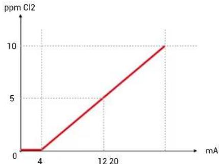
line
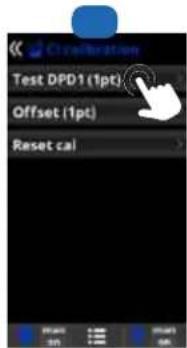
| mA | ppm Cl2 | | ---- | ------- | | 4 | 0 | | 12 | 5 | | >20 | 10 |1 Calibration of the free chlorine sensor equipped with a membrane: It is recommended to do this once a week during the season the pool is in use.
2 Before beginning the calibration, measure the pool free chlorine (in ppm) by performing a DPD1 analysis and click on Test DPD1.
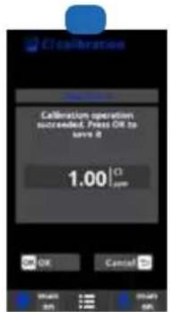
3 Step 1 of 3: Enter the value measured during the DPD1 analysis and press OK.
4 Step 3 of 3: Press OK to validate the calibration.
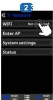
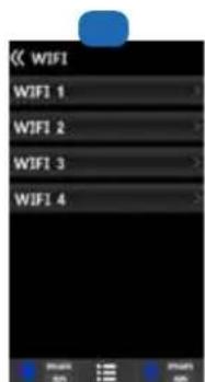
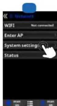
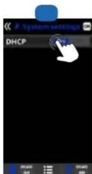
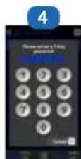
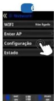
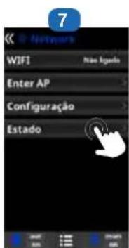
6g. Installing the WiFi or Ethernet module
1 Open the cover and connect the WiFi module to the WIFI slot (see section 3C). The Network menu appears automatically in the Settings menu. The power LED remains steady and the connection LED flashes
![B:\MyVersion\Type network AP name [1] 1 2 3 a 5 a 6 b 9 d 4 b c d e f g h i j b l m u p q r v t u v w x y z i ... ABC N&U OK Cancel OK Cancel](/content/2026/04/623881/images/8095d9cb039d947c5438c15a7549df3c2fa903bd57bd5e030d441a39c1c6f844.jpg)
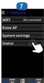
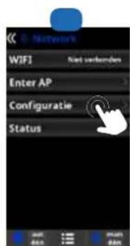
1 Internet: Once the module is connected, switch on the device. A Network menu appears in the Settings menu.
2 Wifi: Select the Wifi menu to start an automatic search for available networks.
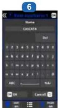
3 Choose the relevant available network.
4 Enter the password for this network via the keyboard. To confirm, press OK.
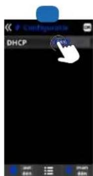
5 Configuration: If you want to configure your connection manually or if automatic configuration fails, you can change the network parameters in this menu.
6 The default setting "DHCP = ON" must be left as it is.
7 Status: Displays information about your current connection.

6h. Installing and starting up a variable-speed pump
To install and control a 3-speed pump, please contact your dealer.
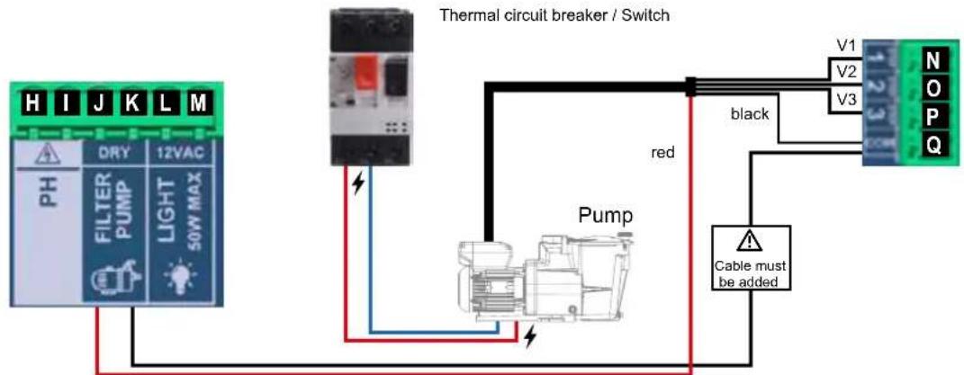
flowchart
graph TD
    A["Thermal circuit breaker / Switch"] --> B["Pump"]
    B --> C["V1: V2: V3"]
    B --> D["Cable must be added"]
    B --> E["black"]
    B --> F["red"]
    B --> G["50V MAX"]
    H["PH"] --> I["DRY"]
    I --> J["12VAC"]
    K["FILTER PUMP"] --> L["Light"]
    M["50V MAX"] --> N["Light"]
    O["Black"] --> P["V1"]
    Q["N"] --> R["V2"]
    S["OP"] --> T["V3"]
    U["PQ"] --> V["12V3"]
Diagram of variable-speed pump installation on the AquaRite® UV LS


3 Enter the service menu from the configuration menu.
4 Enter the password (contact your dealer to obtain the password).
5 Enter the pump type menu.
6 Select the type of pump.
The default pump type is "standard" (single-speed). When using a variable-speed
pump, select variable speed A, B or C. In this case, one of the 3 default speeds (V1, V2, V3) can be assigned to the heating and for when the cover is closed.
i Select Var. speed A for a Hayward variable-speed pump.

After connecting a variable speed pump, you can assign a different speed individually to each filtration period, as required. V1: S, V2: M, V3: F Filter cleaning: To clean the filter with a variable speed pump, it is best to use the highest speed (V3).
7. SERVICING
During the first 10-15 days, your system will require more attention:
- Check that the pH remains at the ideal level (7.2 to 7.4).
- If the pH is exceptionally unstable and uses a lot of acid, check the alkalinity (see table Chemical water balance).
If the balance is highly unstable, contact your pool installer/builder.
REMEMBER that the system needs a certain amount of time to adapt to your pool and will require additional chemicals during the first 3-5 days.
The pool must be regularly maintained and the skimmer baskets emptied whenever necessary.
Also check that your filter is not clogged.
ADD WATER: It is preferable to add water via the skimmers so that it passes through the cell before entering the pool.
Remember to check the salt percentage after adding water.
DOSING PUMPS: Regularly check the acid level to ensure that the pump does not run dry. The dosing pump must be checked and serviced at regular intervals. The Santoprene tube of the peristaltic pump has a lifetime of 2 years. We recommend that you change it once a year.
Servicing the pH probe
The probe must be clean and free from oil, chemical deposits and contamination to function properly. As it is in continuous contact with the water in the pool, the probe may need to be cleaned weekly or monthly, depending on the number of bathers and other specific characteristics of your pool. A slow response, more frequent pH calibration and inconsistent readings indicate that the probe needs to be cleaned.
To clean the probe, turn off the power to the AquaRite® UV LS.
Unplug the probe connector from the unit, unscrew the probe and carefully remove it from the chamber. Clean the probe bulb with a soft toothbrush and regular toothpaste.
A household washing-up liquid detergent may also be used to remove any oil.
Rinse with fresh water, replace the Teflon tape on the threads, and reinstall the probe.
If the probe continues to give inconsistent readings or requires excessive calibration after it has been cleaned, it should be replaced. The lifetime of the probes is 1 year. We recommend that you calibrate them every month during the season the pool is in use.
Servicing and cleaning the cell
Turn off the main power supply to the AquaRite® UV LS before removing the cell. Once it has been removed, examine the inside of the cell for any traces of scale (whitish brittle or flaky deposits) and debris stuck to the plates. If no deposits are visible, put the cell back in place. If deposits are visible, try to remove them with a garden hose. If this method is unsuccessful, use a plastic or wooden tool to remove deposits stuck to plates (do not use a metal tool as this will damage their coating). A build-up of deposits on the cell indicates an exceptionally high concentration of calcium in the pool water. If you cannot find a solution to this situation, you will have to clean the cell at regular intervals. The best way to avoid this problem is to maintain the chemical composition of the water at the recommended concentrations.
Acid washing: This should only be done in severe cases where flushing will not remove most of the deposits. To acid wash, turn off the main power supply to the AquaRite® UV LS. Remove the cell from the piping. In a clean plastic container, make up a solution of water and acetic or phosphoric acid (such as that used to remove scale from a coffee machine). ALWAYS ADD ACID TO WATER – NEVER ADD WATER TO ACID. Be sure to wear rubber gloves and protective goggles for this operation.
The level of the solution in the container should just reach the top of the cell, so that the wire harness compartment IS NOT under water. It may be helpful to coil up the wire before submerging the cell. Allow the cell to soak for a few minutes, then rinse it with a garden hose. If the deposits are still visible, soak and rinse again. Put the cell back and examine it from time to time.
Probe storage
The end of the probe must always be in contact with water or a solution of KCl. If it is removed from the measuring chamber, it should be stored in the plastic cap provided (filled with water). If the storage cap has been mislaid, the probe should be stored separately in a small glass or plastic container with its end immersed in water.
The probe must always be in a frost-free environment.
8. TROUBLESHOOTING GUIDE
No display
Check the connection cable between the display and the control box.
Check that the 4A fuse is not defective (located inside the control box).
Check the power supply: 210-230 V\~ 50 Hz.
If the problem persists, contact your pool installer/builder.
Excessive chlorine
Check and/or adjust the chlorine production setting.
If your pool has an automatic ORP control system, check the ORP setting.
Check the ORP probe and calibrate, if necessary.
The hydrolysis has not reached the required production rate
Check the concentration of salt in the water (depending on the model).
Check the condition of the cell (it may be dirty or covered in scale).
Clean the cell according to instructions.
Check the flow switch and clean if necessary.
Check that the cell is not worn (contact your pool installer/builder).
Cell scaled up in under a month
Very hard water with high pH and total alkalinity (balance and adjust the pH and total alkalinity of the water).
Check that the system automatically changes polarity (see display).
Impossible to attain a free chlorine level of 1 ppm
Increase the filtration time.
Increase the chlorine production rate.
Check the concentration of salt in the water (see table Chemical water balance).
Check the level of isocyanuric acid in the pool (see table Chemical water balance).
Check that the reactive agents in your test kit are not out of date.
Adjust the chlorine production according to the temperature and the number of pool users.
Adjust the pH to ensure that it is always below 7.8.
Alarm AL3: pH dosing pump stopped
The maximum time allowed to attain the pH set point has been reached. The pH acid dosing pump is stopped to avoid overdosing and acidifying the water.
Please carry out the following checks:
Check that the can of liquid pH is not empty.
Check whether the pH read on the machine corresponds to the pH in the pool (use a pH analysis kit). Otherwise, please calibrate the pH probe or replace it, if necessary.
Check that the pH pump is running normally.
Check the correction time setting.
To make this message disappear and reset the dosing, press on the pH reading circle for 3 seconds.
The screen indicates LOW
Check the water balance and salinity.
Check that the cell is free of scale and clean it if necessary.
See "The hydrolysis has not reached the required production rate".
Water temperature too low.
White flakes in the pool
This occurs when the water is unbalanced and very hard.
Balance the water, check the cell and clean it, if necessary.
The screen indicates FLOW
Check the flow switch and the gas detector.
Check that the filter pump is working.
Check that the pipes are not obstructed (valve closed, basket or strainer full, etc.).
Check that the 4A fuse is not defective.
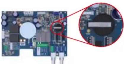
Changing the battery
Unplug the cables that are screwed to the "extension" circuit board.
Unscrew the "extension" circuit board.
Unscrew the black cover of the "main" circuit board.
Change the battery (CR2032 type).
Screw the black cover, the "extension" circuit board, and the cables back in place.
natural_image
Close-up of a printed circuit board with electronic components and a magnified inset showing internal components (no visible text or symbols)
9. WARRANTY CONDITIONS AND EXCLUSIONS FOR EUROPEAN UNION COUNTRIES
All HAYWARD ® products are covered for manufacturing defects or material defects for a warranty period of 3 years as of date of purchase. Proof of purchase, indicating the date of purchase, must be provided with all warranty claims. We would therefore advise you to keep your invoice.
The HAYWARD ® warranty is limited to repair or replacement, as chosen by HAYWARD ® , of the faulty products, provided that they have been used in compliance with the instructions given in the corresponding user guides, provided that the products have not been altered in any way, and provided that they have been used exclusively with HAYWARD ® parts and components. The warranty does not cover damage due to frost and to chemicals. Any other costs (transport, labour, etc.) are excluded from the warranty.
HAYWARD ® may not be held liable for any direct or indirect damage resulting from incorrect installation, incorrect connection, or incorrect operation of the product.
In order to claim on a warranty and in order to request repair or replacement of an article, please ask your dealer.
Equipment returned to our factory will not be accepted unless prior approval has been given.
Wearing parts are not covered by the warranty.
The following wearing parts of the salt chlorinator must be maintained in accordance with their estimated lifetime:
- Titanium cell: 8,000 hours
- UV Lamp: 8000 hours
- Set of seals (titanium cell, probe mount): 2 years
- Santoprene tube (peristaltic pump) - Membrane (electromagnetic pump): 2 years
- Probe (pH, ORP, conductivity, free chlorine): 1 year (warranty 6 months)
10. ENVIRONMENTAL INFORMATION
Provision regarding professional waste from electrical and electronic equipment (WEEE). In compliance with directive 2012/19/EU regarding the management of waste from electrical and electronic equipment, this pump must be disposed of at a waste sorting site.
==> for more information contact your dealer.
Good management of waste from electrical and electronic equipment contributes to the prevention of damage to the environment and human health.
In compliance with directive 2006/66/EC of the European Parliament and of the Council of 6 September 2006 on batteries and accumulators and waste batteries and accumulators, the symbol that accompanies this manual indicates that the battery incorporated into the pump must be disposed of via waste sorting.
When the battery reaches the end of its life, it must be removed and disposed of at a waste sorting site. Instructions for replacement of the battery are given on the previous page.

natural_image
Abstract geometric logo with stylized letter H inside a circular frame (no text or symbols)HAYWARD®

natural_image
Exterior view of a black industrial control unit with digital display and mechanical component (no readable text or symbols)CE EHC UK CA

natural_image
Two simple line icons: a folded map with an information symbol and an open book, both without any text or symbols.AquaRite® UV LS
MANUAL DEL USUARIO
CONSERVE ESTE MANUAL PARA CONSULTAS ULTERIORES
HAYWARD

natural_image
Line drawing of a wall-mounted electrical outlet with a cable and power plug (no text or symbols)natural_image
Pure geometric diagram with intersecting lines and a central rectangle (no text or symbols)natural_image
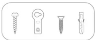
Four different screw and tool icons in a row, no text or symbols present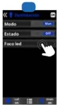
line
| mA | ppm Cl2 | | --- | ------- | | 0 | 0 | | 4 | 0 | | 12 | 5 | | 20 | 10 |
natural_image
Abstract geometric logo with stylized letter H inside a circular frame (no text or symbols)HAYWARD®

natural_image
Exterior view of a black industrial control unit with digital display and mechanical component (no readable text or symbols)CE EAC UK CA

natural_image
Two simple line icons: a folded map with an information symbol and an open book, both without any text or symbols.AquaRite® UV LS
MANUAL DO UTILIZADOR
GUARDE ESTE MANUAL PARA REFERÊNCIA FUTURA

HAYWARD®


1 Iluminação.

line
| mA | ppm Cl2 | | --- | ------- | | 0 | 0 | | 4 | 0 | | 12 | 5 | | 20 | 10 |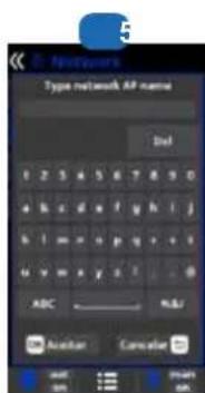
natural_image
Abstract geometric logo with stylized letter H inside a circular frame (no text or symbols)HAYWARD®

natural_image
Exterior view of a black industrial control unit with digital display and mechanical component (no readable text or symbols)CE EHC UK CA

natural_image
Two simple line icons: a folded map with an information symbol and an open book, both without any text or symbols.AquaRite® UV LS
ANWENDERHANDBUCH
BEWAHREN SIE DIESES HANDBUCH ZUM SPÄTEREN NACHSCHLAGEN AUF

HAYWARD®


natural_image
Line drawing of a wall-mounted electrical outlet with a cable and power plug (no text or symbols)natural_image
Pure geometric diagram with intersecting lines and a central rectangle, no text or symbols presentBohrschablone

Hydrolyse-Zelle
Stopfbuchse (X2)
UV-Modul
Anwenderhandbuch
natural_image
Four different types of screw or screwdriver icons, including a threaded screw and two variants with arrows indicating direction (no text or symbols)


line
| mA | ppm Cl2 | | --- | ------- | | 0 | 0 | | 4 | 0 | | 12 | 5 | | 20 | 10 |natural_image
Abstract geometric logo with stylized letter H inside a circular frame (no text or symbols)HAYWARD®

natural_image
Exterior view of a black industrial control unit with digital display and mechanical component (no readable text or symbols)CE EAC UK CA

natural_image
Two simple line icons: an open map with an information symbol and an open book, both without any text or symbols.AquaRite® UV LS GEBRUIKERSHANDLEIDING
BEWAAR DEZE HANDLEIDING VOOR TOEKOMSTIG GEBRUIK

HAYWARD®


WAARSCHUWING: Elektrisch risico.
natural_image
Line drawing of a wall-mounted electrical outlet with a cable and power plug (no text or symbols)natural_image
Pure geometric diagram with intersecting lines and a central rectangle, no text or symbols presentBoorsjabloon
hydrolysecel
Kabelwartel
(X2)
UV-module
natural_image
Four different types of screw or screwdriver icons, no text or symbols present3. INSTALLATIE VAN HET APPARAAT
1 hydrolyse: Programming hydrolyse functions.
The total time corresponds to the cumulative total length of all lamp operating periods.
1 Hulprelais.


line
| mA | ppm Cl2 | | --- | ------- | | 0 | 0 | | 4 | 0 | | 12 | 5 | | 20 | 10 |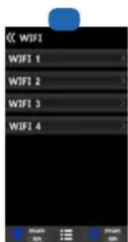


8. PROBLEEMOPLOSSING
Geen beeld
natural_image
Abstract geometric logo with stylized letter H inside a circular frame (no text or symbols)HAYWARD®

natural_image
Exterior view of a black industrial control unit with digital display and mechanical component (no readable text or symbols)CE EHC UK CA

natural_image
Two simple line icons: a folded map with an information symbol and an open book, both without any text or symbols.AquaRite® UV LS
MANUALE D'USO
CONSERVARE QUESTO MANUALE PER USO FUTURO

HAYWARD®


HAYWARD


www.hayward-pool.co.uk
JOIN US AND
follow us on our
SOCIAL NETWORK


- HAYWARD®
- AquaRite® UV Low Salinity
- 3b. Installation murale
- CONDITIONS DE GARANTIE
- ET EXCLUSIONS POUR LES PAYS DE L'UNION EUROPÉENNE
- WARNING: Electrical hazard.
- INDEX
- General
- Pack contents
- Installation
- Prerequisites for starting up the hydrolysis
- 5.Operation
- Connecting and configuring peripherals
- Servicing
- Troubleshooting Guide
- Warranty conditions and exclusions for European union countries
- Environmental information
- 3b. Wall-mounted installation
- 3c. Installation and connection of the electronic circuit boards
- 3d. Cabling the box
- 3e. Installation of the cell and the mechanical flow switch
- Installation and connection of the cell (see diagram):
- Installation and connection of the mechanical flow switch:
- Preparing the pool water
- Salt concentration
- Type of salt to use
- How to add or remove salt
- Quantity of stabilizer (CYANURIC ACID in kg) required for 25 ppm
- Chemical water balance
- OPERATION
- 5a. View and description of the home screen
- 5b. Commissioning of the device
- 5e. Installing and configuring the ultraviolet module
- Configuring the UV module:
- 5f. Filtration control
- 5g. Control and power supply for lighting
- 5h. Control of auxiliary relays
- 6a. Installing and starting up the pH option
- Connecting the pH dosing pump
- Operation of pH corrector dosing pump:
- Installing and preserving the pH probe:
- 6b. Installing and starting up the ORP option
- Installing and preserving the ORP probe:
- Setting the ORP level
- 6c. Installing and starting up the temperature probe
- 6d. Installing and starting up a heat pump
- 6e. Installing and starting up the free chlorine option (amperometric sensor)
- 6f. Installing and starting up the free chlorine option (membrane sensor)
- 6g. Installing the WiFi or Ethernet module
- System settings
- 6h. Installing and starting up a variable-speed pump
- Servicing the pH probe
- Servicing and cleaning the cell
- Probe storage
- No display
- Excessive chlorine
- The hydrolysis has not reached the required production rate
- Cell scaled up in under a month
- Impossible to attain a free chlorine level of 1 ppm
- Alarm AL3: pH dosing pump stopped
- The screen indicates LOW
- White flakes in the pool
- The screen indicates FLOW
- Changing the battery
- HAYWARD
- Iluminação.
- WAARSCHUWING: Elektrisch risico.
- INSTALLATIE VAN HET APPARAAT
- Hulprelais.
- PROBLEEMOPLOSSING
- Geen beeld
Brand : HAYWARD
Model : AquaRite UV LS
Category : Water pump