
TPS-200H - Saw HiKOKI - Free user manual and instructions
Find the device manual for free TPS-200H HiKOKI in PDF.

| Product Type | Pole saw attachment (pruner) |
| Brand | HiKOKI |
| Model | TPS-200H |
| Category | Saw |
| Guide bar length | 200 mm |
| Chain pitch | 3/8 in (9.525 mm) |
| Chain gauge | 0.043 in (1.1 mm) |
| Maximum cutting capacity | 200 mm (8 in) |
| Chain type | Cutter link |
| Lubrication | Automatic, chain oil |
| Oil tank capacity | Approximately 100 ml |
| Weight (without guide bar and chain) | Approximately 2.5 kg |
| Power source | Brushcutter engine (compatible) |
| Sound pressure level (LpA) | 85 dB(A) (indicative value) |
| Sound power level (LwA) | 100 dB(A) (indicative value) |
| Vibration level (front handle) | 3.5 m/s² (indicative value) |
| Safety | Safety glasses, helmet, hearing protection, gloves, non-slip shoes |
| Maintenance | Regular cleaning, chain sharpening, tension check |
| Spare parts | Guide bar, chain, side cover, sprocket |
| Repairability | By authorized Tanaka/HiKOKI dealer |
Frequently Asked Questions - TPS-200H HiKOKI
User questions about TPS-200H HiKOKI
0 question about this device. Answer the ones you know or ask your own.
Ask a new question about this device
Download the instructions for your Saw in PDF format for free! Find your manual TPS-200H - HiKOKI and take your electronic device back in hand. On this page are published all the documents necessary for the use of your device. TPS-200H by HiKOKI.
USER MANUAL TPS-200H HiKOKI
natural_image
Technical line drawing of a mechanical clamp or tool assembly (no text or symbols)
en Handling instructions
de Bedienungsanleitung
fr Mode d'emploi
it Istruzioni per l'uso
nl Gebruiksaanwijzing
es Instrucciones de manejo
pt Instruções de uso
el Οδηγίες χειρισμού
1
text_image
15M2
text_image
15M (50ft.)3
natural_image
Illustration of a person wearing a helmet and safety harness, holding a safety harness (no text or symbols present)4
natural_image
Technical line drawing of a mechanical component with a bolt and lever, showing a directional arrow (no text or symbols)5
text_image
Technical diagram of a mechanical device with numbered components and directional arrow indicating motion6
text_image
Technical diagram of a mechanical device with numbered parts labeled 5, 6, and a central component.7
text_image
Technical diagram of a mechanical device with numbered parts labeled 7 through 118
text_image
Technical diagram of a chain-link robotic device with numbered parts and an inset showing chain link components.9
natural_image
Illustration of hands using a chain-linking tool to cut a mechanical part (no text or symbols visible)10|11 12
text_image
0.5~1 mm 14 12 13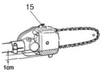
text_image
15 1cm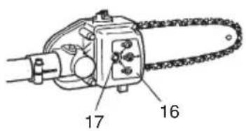
text_image
17 16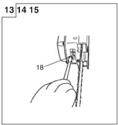
text_image
13 14 15 18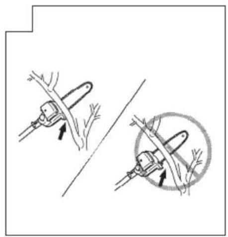
natural_image
Illustration of two manual tools cutting a tree branch, showing blade and root structures (no text or symbols)
natural_image
Diagram of a person using a tool to cut tree branches, no text or symbols present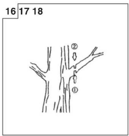
text_image
16 17 18 ② ①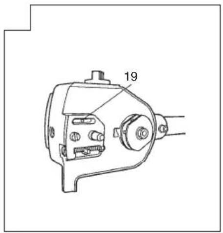
text_image
19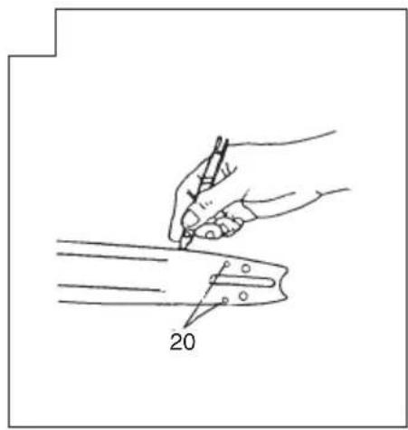
natural_image
Line drawing of a hand holding a pen writing on a cutting board, with the number 20 labeled (no text or symbols beyond the number)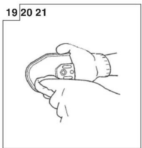
natural_image
Line drawing of a hand holding a small mechanical component, labeled 19-21 (no text or symbols on the diagram itself)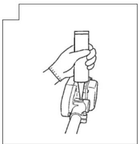
natural_image
Line drawing of a hand holding a cylindrical object with a tool, no text or symbols present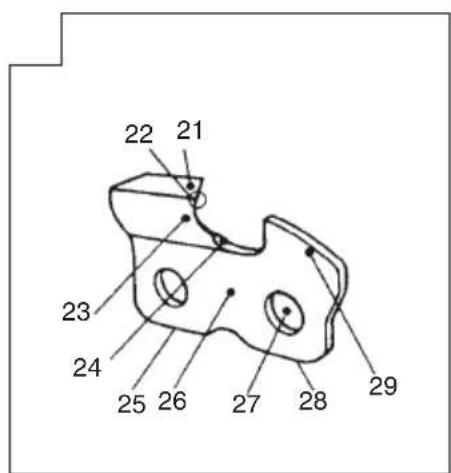
text_image
22 21 23 24 25 26 27 28 29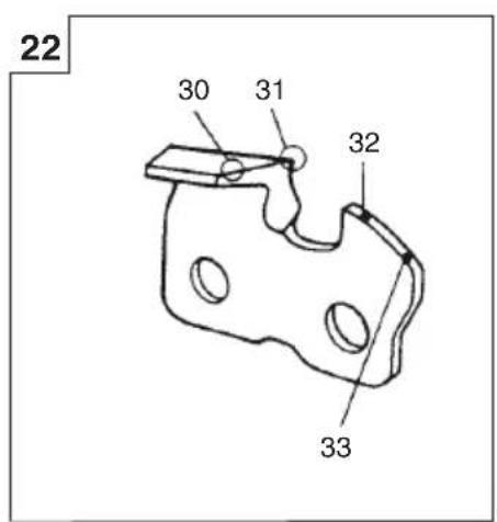
text_image
22 30 31 32 33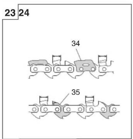
text_image
23 24 34 35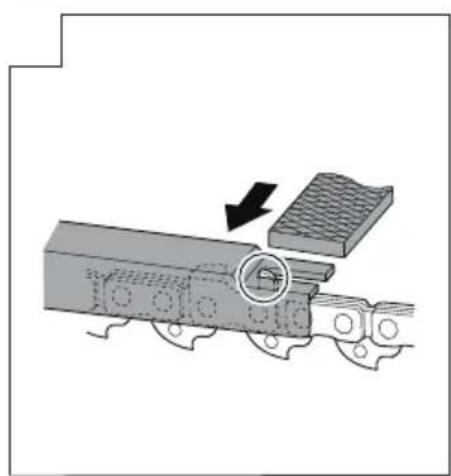
natural_image
Mechanical assembly diagram showing a moving train with a component being processed (no text or symbols visible)25|26 27
natural_image
Simple line drawing of a wooden table with woven pattern and curved legs (no text or symbols)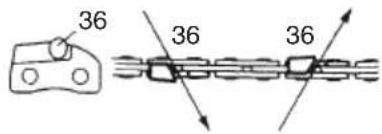
text_image
36 36 36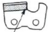
37 38
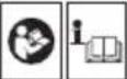
MEANINGS OF SYMBOLS
NOTE: Some units do not carry them.
| Symbols⚠ WARNINGThe following show symbols used for the machine. Be sure that you understand their meaning before use. | |||
 | Pole Saw | 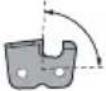 | Side plate fi ling angle |
 | It is important that you read, fully understand and observe the following safety precautions and warnings. Careless or improper use of the unit may cause serious or fatal injury. | 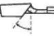 | Top plate angle |
 | Read, understand and follow all warnings and instructions in this manual and on the unit. | 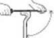 | File guide angle |
 | Always wear eye, head and ear protectors when using this unit. | 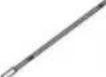 | File |
 | Keep all children, bystanders and helpers 15 m away from the unit. If anyone approaches you, stop the engine and cutting attachment immediately. | 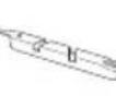 | Depth gauge |
 | Chain oil tank capacity |  | Gloves should be worn when necessary, e.g., when assembling cutting equipment. |
 | Dry weight(Without guide bar and chain) |  | Use anti-slip and sturdy footwear. |
 | Guide bar length |  ISO22868 ISO22868 | Sound pressure level LpA by ISO 22868 Equivalent* |
 | Chain pitch |  ISO22868 ISO22868 | Sound power level LwA by ISO 22868 Racing |
 | Chain gauge | a  (F) (F) | Vibration level by ISO 22867 Front or Left handle / Equivalent* |
 | Type of chain | a  (R) (R) | Vibration level by ISO 22867 Rear or Right handle / Equivalent* |
 | Depth gauge setting |  | Uncertainty |
| NOTE: Equivalent noise level / vibration level are calculated as the time-weighted energy total for noise / vibration levels under various working conditions with the following time distribution:* 1/2 Idle, 1/2 racing. | |||
NOTE: Equivalent noise level / vibration level are calculated as the time-weighted energy total for noise / vibration levels under various working conditions with the following time distribution:
* 1/2 Idle, 1/2 racing.
INTRODUCTION
It is important that you read and understand your Tanaka brush cutter owner's manual as well as this manual.
Please carefully review and observe all safety precautions and warnings.
Careless or improper use of the unit may cause serious or fatal injuries.
This pole trimmer attachment has been designed for certain Tanaka brush cutters.
SAFE OPERATION
WARNING ▲DANGER
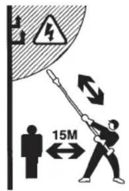
All overhead electrical conductors and communications wires can have electricity flow with high voltages.
Never touch wires directly or indirectly when trimming, otherwise serious injury or death may result.
○ Review the area to be trimmed. Look for hazards that could contribute to unsafe conditions. DO NOT operate unit if any wires (power, telephone, cable, etc.) are closer than 15 m (50 ft) to any part of the operator or unit. (Fig. 1)
English
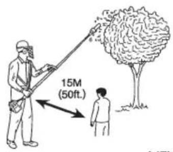
○ Spectator and fellow workers must be warned, and children and animals prevented from coming nearer than 15 m (50 ft) while the pole trimmer is in use. (Fig. 2)
○ Avoid all power lines. This unit is not insulated against electrical current.
○ Always wear head protection with full face shield to help protect against falling branches and debris. (Fig. 2)
○ Gloves should be used when sharpening chain.
○ Always wear heavy, long pants, boots and gloves.
Do not wear loose clothing, jewelry, short pants, sandals or go barefoot.
Secure hair so it is above shoulder length.
○ Wear hearing protection. Pay attention to your surroundings.
Be aware of any bystanders who may be signaling a problem.
○ Use anti-slip and sturdy footwear.
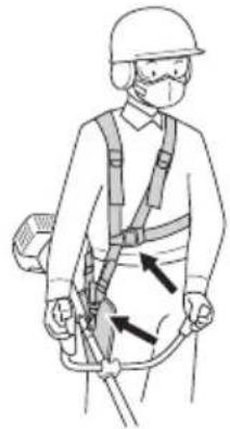
Before pruning, attach the harness to suspension eyelet and hang from the shoulder.
Adjust the harness to be easy to use.
Always wear the harness during operation.
○ Pull emergency release flap in the event of emergency.
○ National regulation can restrict the use of machine.
○ Keep from footing and balance. Do not over-reach.
When operation is prolonged, take a break periodically so that you may avoid possible Hand-Arm Vibration Syndrome (HAVS) which is caused by vibration.
○ Press the quick release button or pull emergency release flap (If so equipped) in the event of emergency. (Fig. 3)

WARNING
○ Antivibration systems do not guarantee that you will not sustain Hand-Arm Vibration Syndrome or carpal tunnel syndrome.
Therefore, continual end regular users should monitor closely the condition of their hands and fi ngers. If any of the above symptoms appear, seek medical advice immediately.
○ Long or continuous exposure to high noise levels may cause permanent hearing impairment. Always wear approved hearing protection when operating a machine. Failure to do so could result in a high risk of personal accidents or injury.
Unit/machine safety

WARNING
Never modify the unit/machine in any way. Do not use your unit/machine for any job except that for which it is intended.
○ Using guide bar/chain other than recommended by the manufacturer which are not approved, could result in a high risk of personal accidents or injury.
Transport and storage
○ Clean and maintain the unit carefully and store it in a dry place.
○ When transporting or storage, cover chain with chain cover.
ASSEMBLY PROCEDURES
Installation of cutting attachment
-
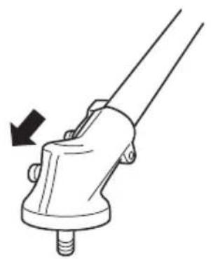
Remove angle transmission from your brush cutter. (Fig. 4)
-
Join the attachment in place of it.
NOTE
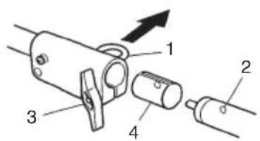
If your brush cutter tube is 26 mm diameter, remove bracket collar B (4) by pulling the lock pin (1). (Fig. 5)
-
Make sure the lock pin (1) fits in the location hole (2) of tube and that the tube will not come off. (Fig. 5)
-
Tighten the knob nut (3) securely. (Fig. 5)
WARNING
Never try to start engine without side case securely fastened.
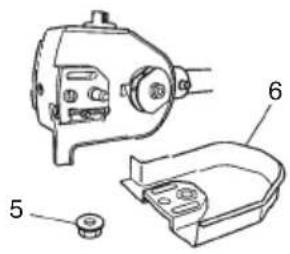
Installation of bar and chain
-
Remove chain bar clamp nut (5). (Fig. 6)
-
Remove the side case (6). (Fig. 6)
-
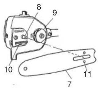
Install, the chain bar (7) onto the bolt (8), then push it toward the sprocket (9) as far as it will go. Make sure that the boss of chain tension adjusting bolt (10) fits into the hole of the bar (11). (Fig. 7)
NOTE
Slightly move the bar back and forth and make sure the chain tension boss (10) fits into the hole (11) in the bar properly.
-
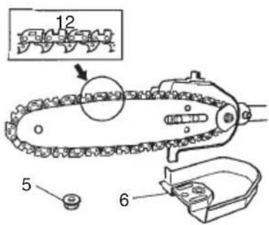
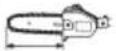
Confirm the direction of saw chain (12) is correct as in the figure, and align the chain on the sprocket. (Fig. 8)
-
Guide the chain drive links into the bar groove all around the bar.
-
Install the side case (6) onto the guide bar clamp bolt. Then fix the clamp nut (5) temporarily. (Fig. 8)
-
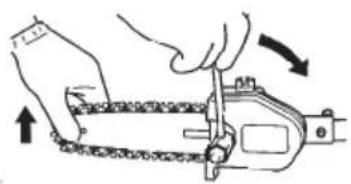
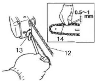
Raise the bar end, and tighten the chain (12) by turning the tension adjustment bolt (13) clockwise. To check proper tension, lightly lift up the center of chain and there should be about 0.5 - 1.0 mm clearance between bar and edge of drive link (14). (Fig. 9, 10)
CAUTION
PROPER TENSION IS EXTREMELY IMPORTANT! (Fig. 9, 10)
-
Raise the bar end and securely tighten the chain bar clamp nut with the box wrench. (Fig. 9)
-
A new chain will stretch so adjust the chain after a few cuts and watch chain tension carefully for the first half hour of cutting.
NOTE
Check the chain tension frequently for optimum performance and durability.
CAUTION
When the chain is excessively tightened, the bar and chain will be damaged rapidly. Conversely, when the chain is excessively loosened, it may get out of the groove in the bar.
○ Always wear gloves when touching the chain.
WARNING
During operation, hold the unit firmly with both hands. A single hand operation may cause serious injury.
Chain oil (Fig. 11)
Fill up with chain oil (15). Always use good quality chain oil. When the engine is running, the chain oil is automatically discharged.
NOTE
Add chain oil when its level lowers to one centimeter from bottom. (Fig. 11)
ADJUSTMENT OF CHAIN OIL SUPPLY
The chain oil quantity discharged through the lubrication system is factory-adjusted to the standard. Adjust the quantity in accordance with the operating condition.
The numbered label (16) describes order of chain oil adjustment. (Fig. 12)
○ Loosen the fixing screw (17) one turn. (Fig. 12)
○ Turn the adjusting screw (18) clockwise to decrease the quantity and turn it counterclockwise to increase the quantity. (Fig. 13)
☐ Do not try to turn the screw (18) clockwise beyond 1 turn from its most counterclockwise position or the maximum quantity discharged position.
○ After adjustment has been made, tighten fixing screw (17). (Fig. 12)
NOTE
When you have lost the proper position of the screw (18), start with the most counterclockwise position.
PRUNING TECHNIQUES
This attachment is designed for pruning small limbs and branches up to 8" in diameter. Follow these tips for successful operation.
- Plan cut carefully. Check direction branch will fall.
○ Long branches should be removed in several pieces.
○ Do not stand directly beneath branch being cut. Falling limbs may bounce when they hit the ground.
When ready to cut: Hold "front cutting guide" against branch. This will prevent whipping of the branch. DO NOT use back and forth sawing action. (Fig. 14)
○ Look out for branch immediately behind the branch being cut. If blade hits rear branch damage to blade may occur. (Fig. 15)
○ Accelerate to full throttle.
○ Apply a light cutting pressure.
- Ease cutting pressure when nearing end of cut to maintain control.
○ When pruning a limb 4 inch diameter or larger, cut as follows: (Fig. 16)
-
Undercut 1/4 limb diameter near tree trunk.
-
Finish top cut slightly farther out on limb.
-
Flush cut stub at trunk.
○ DO NOT use for felling or bucking.
MAINTENANCE
Oiler port (Fig. 17)
Clean the chain oiler port (19) whenever possible.
Guide bar (Fig. 18)
Before using the machine, clean the groove and oiler port (20) in the guide bar.
Side case (Fig. 19)
Always keep the side case and drive area clean of saw dust and debris.
Gear case (Fig. 20)
Check gear case for grease level about every 50 hours of operation by removing the grease filler plug on the top of gear case.
If no grease can be seen on the flanks of the gears, fill the gear case with a quality lithium based multipurpose grease up to 3/4.
Do not completely fill the gear case.
CHAIN SHARPENING
Parts of a cutter (Fig. 21, 22)

WARNING
○ Gloves should be used when sharpening chain.
☐ Be sure to round off the front edge to reduce the chance of kickback or tie-strap breakage.
-
Top plate
-
Cutting corner
-
Side plate
-
Gullet
-
Heel
-
Chassis
-
Rivet hole
-
Toe
-
Depth gauge
-
Correct angle on top plate (degree of angle depends on chain type)
-
Slightly protruding "hook" or point (curve on non-chisel chain)
-
Top of depth gauge at correct height below top plate
-
Front of depth gauge rounded off
LOWERING DEPTH GAUGES WITH A FILE
WARNING
Do not smoothen the upper part of the guard tie straps (34) or bumper drive links (35) with a file or deform them. (Fig. 23)
○ Adjust the depth gauge to the specified setting.
Failure to observe the above raises the possibility of a kickback and may result in injury.
1) If you sharpen your cutters with a file holder, check and lower the depth.
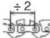
2) Check depth gauges every third sharpening.
3) Place depth gauge tool on cutter. If depth gauge projects, file it level with the top of the tool. Always file from the inside of the chain toward an outside cutter. (Fig. 24)
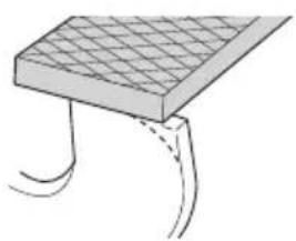
4) Round off front corner to maintain original shape of depth gauge after using depth gauge tool. Always follow the recommended depth gauge setting found in the maintenance or operator manual for your chain saw. (Fig. 25)
GENERAL INSTRUCTIONS FOR FILING CUTTERS
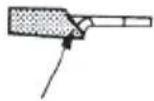
File (36) cutter on one side of the chain from the inside out. File on forward stroke only. (Fig. 26)
5) Keep all cutters the same length. (Fig. 23)
6) File enough to remove any damage to cutting edges (side plate (37) and top plate (38)) of cutter. (Fig. 27)
SHARPENING ANGLES FOR SHARPENING SAW CHAIN
The SHARPENING ANGLES FOR SHARPENING SAW
CHAIN of this machine are listed in the table on page 36.
Maintenance schedule
Below you will find some general maintenance instructions.
For further information please contact Tanaka dealer.
Inspection and service before use
Daily maintenance
○ Clean the exterior of the unit.
○ Clean the chain oil filter port.
○ Clean the groove and oil filter port in the guide bar.
○ Clean the side case of saw dust.
○ Check that the saw chain is sharp.
- Check that the guide bar clamp nuts are sufficiently tightened.
○ Make sure that the guide bar cover is undamaged and that it can be securely fitted.
○ Check that nuts and screws are sufficiently tightened.
☐ Check the tip of the guide bar. Please exchange it for the new one when it is worn out.
Monthly maintenance
○ Clean chain oil fi iter.
SYMBOLBEDEUTUNGEN
Installing Guide Bar and Saw Chain
natural_image
Line drawing of a quill pen in an inkwell (no text or symbols)
natural_image
Line drawing of a quill pen in an inkwell (no text or symbols)| English Italiano | ||
| EC DECLARATION OF CONFORMITYWe declare under our sole responsibility that Pole Saw Attachment, identified by type and specific identification code *1), is in conformity with all relevant requirements of the directives *2) and standards *3). Technical fi le at *4) – See below.The European Standard Manager at the representative office in Europe is authorized to compile the technical fi le.Notifi ed body: 0404, SMP Svensk Maskinprovning AB, Box 7035, SE-750 07, Uppsala, Sweden has carried out a EC type examination according to Article 12, clause 3b. The notified body has issued EC type examination certificate no. 0404/18/2502 according to Annex IX, clause 4.The declaration is applicable to the product affi xed CE marking. | DICHIARAZIONE DI CONFORMITÀ CEDhiariamo sotto la nostra esclusiva responsabilità che l'Accessorio potatore, identificato dal tipo e dal codice identificativo specifico *1), è conforme a tutti i requisiti delle direttive *2) e degli standard *3). Documentazione tecnica presso *4) – Vedere sotto.Il gestore delle norme europee presso l'ufficio di rappresentanza in Europa è autorizzato a compilare il fascicolo tecnico.Ente notificato: 0404, SMP Svensk Maskinprovning AB, Box 7035, SE-750 07, Uppsala, Svezia, ha eseguito un esame di tipo CE in conformità con l'Articolo 12, par. 3b. L'ente notificato ha emesso un certificato di esame di tipo CE n. 0404/18/2502 secondo l'Allegato IX, par. 4.La dichiarazione è applicabile ai prodotti cui sono applicati i marchi CE. | |
| Deutsch NederlandsEG-KONFORMITÄTSERKLÄRUNGWir erklären in alleiniger Verantwortung, dass der durch den Typ und den spezifischen Identifizierungscode *1) identifizierte Hochentastervorsatz allen einschlägigen Bestimmungen der Richtlinien *2) und Normen *3) entspricht. Technische Unterlagen unter *4) – Siehe unten.Die Leitung der repräsentativen Behörde für europäische Normen und Richtlinien ist berechtigt, die technischen Unterlagen zusammenzustellen.Benannte Stelle: 0404, SMP Svensk Maskinprovning AB, Postf. 7035, SE-750 07, Uppsala, Schweden hat eine EG-Untersuchung gemäß Artikel 12, Klausel 3b durchgeführt. Die benannte Stelle hat das EG-Untersuchungszertifikat Nr. 0404/18/2502 gemäß Anhang IX, Klausel 4 ausgestellt.Die Erklärung gilt für die an dem Produkt angebrachte CE-Kennzeichnung. | EC VERKLARING VAN CONFORMITEITWij verklaren onder onze eigen verantwoordelijkheid dat Motor Opzet/stokzaag opzetstuk, geïdentificeerd door het type en de specifieke identificatiecode *1), voldoet aan alle relevante vereisten van de richtlijnen *2) en normen *3). Technische documentatie bij*4) – zie onder.De Europese Normen Manager bij de vertegenwoordiging in Europa is gemachtigd om het technisch dossier samen te stellen.Aangemelde instantie: 0404, SMP Svensk Maskinprovning AB, Box 7035, SE-750 07, Uppsala, Zweden, heeft een EC-type keuring volgens artikel 12, punt 3b uitgevoerd. De aangemelde instantie heeft een EC-type keuringscertificaat uitgegeven met het nummer 0404/18/2502 volgens bijlage IX, punt 4.Deze verklaring is van toepassing op producten voorzien van de CE-markeringen. | |
| Français EspañolDECLARATION DE CONFORMITE CENous déclarons sous notre entière responsabilité que l' accessoire pour élagueuse sur perche, identifié par le type et le code d'identification spécifique *1) est en conformité avec toutes les exigences applicables des directives *2) et des normes *3). Dossier technique en *4) - Voir ci-dessous.Le Gestionnaire des normes européennes du bureau de représentation en Europe est autorisé à constituer le dossier technique.Organisme notifié : 0404, SMP Svensk Maskinprovning AB, Box 7035, SE-750 07, Uppsala, Suède a procédé à un examen de type CE conformément à l'article 12, clause 3b. L'organisme notifié a émis un certificat d'examen de type CE n° 0404/18/2502 conformément à l'Annexe IX, clause 4.Cette déclaration s'applique aux produits désignés CE. | DECLARACIÓN DE CONFORMIDAD DE LA CEDeclaramos bajo nuestra única responsabilidad que el Accesorio para podadora de altura, identifica do por tipo y por código de identificación específico *1), está en conformidad con todas las disposiciones correspondientes de las directivas *2) y de las normas *3). Documentación técnica en *4) – Ver a continuación.El Director de Normas Europeas en la oficina de representación en Europa está autorizado para elaborar el expediente técnico.Organismo notificado: 0404, SMP Svensk Maskinprovning AB, Box 7035, SE-750 07, Uppsala, Suecia ha realizado un examen tipo CE conforme al artículo 12, cláusula 3b. El organismo notificado ha emitido el certificado de examen tipo CE n° 0404/18/2502 conforme al Anexo IX, cláusula 4.La declaración se aplica al producto con marcas de la CE. | |
| *1)*2) 2006/42/EC, 2000/14/EC, 2014/30/EU, 2011/65/EU*3) EN ISO 11680-1:2011 | ||
| *4) Representative office in EuropeHikoki Power Tools Deutschland GmbHSiemensring 34, 47877 Willich, GermanyHead office in JapanKoki Holdings Co., Ltd.Shinagawa Intercity Tower A, 15-1, Konan 2-chome,Minato-ku, Tokyo, Japan |  | 29. 3. 2019Naoto YamashiroEuropean Standard Manager29. 3. 2019 A. NakagawaCorporate Officer A. NakagawaCorporate Officer |
| Português Ελληνικά | ||
| DECLARAÇÃO DE CONFORMIDADE CEDeclaramos, sob nossa única e inteira responsabilidade, que o Acessório para podadora de altura, identificado por tipo e código de identificação específico *1), está em conformidade com todos os requisitos relevantes das diretivas *2) e normas *3). Ficheiro técnico em *4)-Consulte abaixo.O Gestor de Normas Europeias no escritório de representação na Europa está autorizado a compilar o fi cheiro técnico.Organismo notificado: 0404, SMP Svensk Maskinprovning AB, Box 7035, SE-750 07, Uppsala, Suécia efectuou um exame tipo CE de acordo com o Artigo 12, cláusula 3b. O organismo notificado emitiu um certificado de exame tipo CE n.° 0404/18/2502 de acordo com o Anexo IX, cláusula 4.A declaração aplica-se aos produtos com marca CE. | EK ΔΗΛΩΣΗ ΕΝΑΡΜΟΝΙΣΜΟΥΔηλώνουμε με αποκλειστική μας ευθύνη ότι το Προσάρτημα Κονταροπρίονου, το οποίο προσδιορίζεται από τον τύπο και τον ειδικό αναγνωριστικό κωδικό *1), είναι σύμφωνο με όλες τις σχετικές απαιτήσεις των Οδηγιών *2) και τα σχετικά πρότυπα *3). Τεχνικό Άρχείο στο *4) – Δείτε παρακάτω.O Διαχειριστής Ευρωπαϊκών Προτύπων στο γραφείο εκπροσώπησης στην Ευρώπη είναι εξουσιοδοτημένος για τη σύνταξη του τεχνικού φακέλου.Διακοινωμένος φορέας: 0404, SMP Svensk Maskinprovning AB, Box 7035, SE-750 07, Ουψάλα, Σουηδία, έχει διεξάγει μια εξέταση τύπου ΕΚ σύμφωνα με το Άρθρο 12, διάταξη 3b. Ο διακοινωμένος φορέας έχει εκδώσει ένα αριθμό 0404/18/2502 πιστοποιητικού εξέτασης τύπου ΕΚ σύμφωνα με το Παράρτημα ΙΧ, διάταξη 4.Η δήλωση ισχύει μόνο για το προϊόν που είναι τοποθετημένη σήμανση CE. | |
| *1)*2) 2006/42/EC, 2000/14/EC, 2014/30/EU, 2011/65/EU*3) EN ISO 11680-1:2011 | ||
| *4) Representative offi ce in EuropeHikoki Power Tools Deutschland GmbHSiemensring 34, 47877 Willich, GermanyHead offi ce in JapanKoki Holdings Co., Ltd.Shinagawa Intercity Tower A, 15-1, Konan 2-chome,Minato-ku, Tokyo, Japan | 29. 3. 2019Naoto YamashiroEuropean Standard Manager29. 3. 2019A. NakagawaCorporate Offi cer | |