
148105 - Barbecue Hendi - Free user manual and instructions
Find the device manual for free 148105 Hendi in PDF.
| Product type | Gas barbecue |
| Brand | Hendi |
| Model | 148105 |
| Usage | Outdoor only |
| Power supply | Butane/propane gas (LPG) |
| Number of burners | 2 (estimated) |
| Thermal power | ~8 kW (estimated) |
| Dimensions (L × P × H) | Approximately 110 × 60 × 90 cm (estimated) |
| Net weight | Approximately 30 kg (estimated) |
| Main material | Stainless steel (stainless parts) and painted steel |
| Ignition system | Piezoelectric |
| Safety device | Thermocouple (automatic shut-off in case of flameout) |
| Recommended gas cylinder | Minimum capacity of 10 kg, placed next to the appliance |
| Gas hose | Maximum length 1.5 m (standard EN16436-1:2014+A3:2020) |
| Cooking grates | Included |
| Griddle plate | Included |
| Drip tray | Included |
| Maintenance | Self-cleaning: burn at maximum power for 10 minutes after use |
| Cleaning the grates | Special barbecue cleaning product |
| Repairs | Must be carried out by a qualified technician |
| Warranty | 12 months |
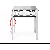
| Assembly | On supplied frame with wheels |
| Standards | Regulator EN16129:2013 - Hose EN16436-1:2014+A3:2020 |
Frequently Asked Questions - 148105 Hendi
User questions about 148105 Hendi
0 question about this device. Answer the ones you know or ask your own.
Ask a new question about this device
Download the instructions for your Barbecue in PDF format for free! Find your manual 148105 - Hendi and take your electronic device back in hand. On this page are published all the documents necessary for the use of your device. 148105 by Hendi.
USER MANUAL 148105 Hendi
You should read this user manual carefully before using the appliance.
Keep these instructions with the appliance. Diese Gebrauchsanweisung bitte beim Gerät aufbewahren. Bewaar deze handleiding bij het apparaat. Zachowaj instrukcję urządzenia. Conservate le istruzioni insieme all'apparecchio. Pästrați maualut de utilizare alături de aparat. Tento návod si odložte so spotrebičom. Хранить руководство вместе с устройством. Филážte autės tics oðnyíeç mazi me tn osukeuń. Uchovávejte tuto příručku se spotřebičem. Tento návod si odložte so spotrebičom. Ezeket az utasításokat tartsa a készülék mellett. Čuvajte ove upute s uređajem.


Thank you for purchasing this Hendi appliance. Read this manual carefully, paying particular attention to the safety regulations outlined below, before installing and using this appliance for the first time.
Safety regulations
- Only use this appliance outdoors.
- Incorrect operation and improper use of the appliance can seriously damage the appliance and injure users.
- The appliance may only be used for the purpose it was intended and designed for. The manufacturer is not liable for any damage caused by incorrect operation and improper use.
- Never try to open the casing of the appliance yourself.
- Do not insert any objects in the casing of the appliance.
- Do not use the appliance after it has fallen or is damaged in any other way. Have it checked and repaired, if necessary, by a certified repair company.
- Do not try to repair the appliance yourself. This could give rise to life-threatening situations.
• Always keep an eye on the appliance when in use. - Children do not understand that incorrect use of appliances can be dangerous. Therefore, never let children use appliances without supervision.
- Do not use any extra devices that are not supplied along with the appliance.
- The use of the installation must comply with the applicable national and local regulations.
- This appliance is not intended for use by persons (including children) with reduced physical, sensory or mental capabilities, or lack of experience and knowledge, unless they have been given supervision or instruction concerning use of the appliance by a person responsible for their safety.
- This appliance is intended solely for preparing food.
- Gas and electrical installations should be checked at least once a year.
- Note: the griddle is hot. Let it cool down before touching or removing it.
• We recommend to use only gas cylinders with a capacity of more than 10 kilograms. - Perform gas cylinder replacement away from potential ignition sources.
• Always place the gas cylinder adjacent to the appliance, not underneath it. - If you smell gas immediately close the gas valve of the gas bottle.
- Note that parts of the barbecue can become very hot. Wear protective clothing (gloves) if you must touch them anyway.
- Be careful of the position of the connection flexible tube so as to ensure that it is not subjected to twisting. The hose does not come in contact with hot parts and sharp edges.
- This appliance must be kept away from flammable materials during use.
Special safety instructions
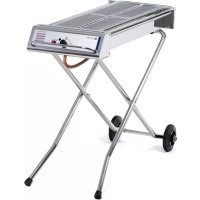
- Position on a flat, stable surface.
- A service agent/qualified technician should carry out installation and any repairs if required. Do not remove any components on this product.
-
Consult Local and National Standards to comply with the following:
-
Health and Safety at Work Legislation
- Fire Precautions
-
Building Regulations
-
DO NOT immerse the appliance in water.
- DO NOT leave the appliance unattended during operation.
- Some surfaces become hot with use - exercise caution when using the appliance.
- Keep this appliance away from children when in use.
- DO NOT move the appliance during cooking.
- DO NOT use if the hose is damaged in any way.
- DO NOT operate the appliance without the cooking grids in place.
- ALWAYS switch off the gas supply to the appliance when not in use.
- ALWAYS store gas bottle upright, even when empty.
- DO NOT use or store gas bottles in direct sunlight.
- DO NOT use if the ambient temperature exceeds 40°C.
- Regularly inspect the hose for any flaws/defects.
- Not suitable for indoor use.
- This appliance must only be used in accordance with these instructions and by persons competent to do so.
- This appliance is not suitable for use by children.
- Keep all packaging away from children. Dispose of the packaging in accordance to the regulations of local authorities.
- WARNING: assembly of the tubing must be conducted by some qualified tuber of destination countries.
- Approved gas regulator(EN16129: 2013) is used according to appliances categories and countries listed in data plate. Approved flexible hose would be changed when the national conditions require it & consult the local regulations, these may differ.
- The tubing or the flexible hose must be changed within the prescribed intervals or with-in one year. The flexible hose should not extend than 1.5m according to standard EN16436-1:2014+A3:2020.
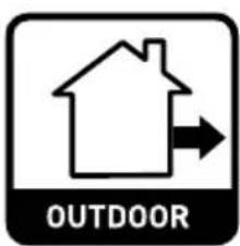
The maximum cylinder dimensions(regulator included) should not exceed (D)50x(H)75cm if no cylinder compartment included.
Intended use
- The device is intended for professional use and can be operated only by qualified personnel.
- This appliance is designed only for grilling appropriate food products. Any other use may lead to damage to the appliance or personal injury.
- Operating the appliance for any other purpose shall be deemed a misuse of the device. The user shall be solely liable for improper use of the device.
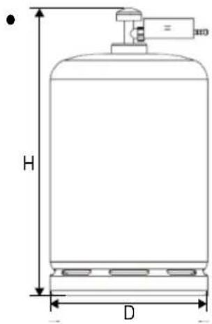
Connecting the gas bottle
1 = Main tap
2 = Pressure regulator
3 = Gas hose
4 = Gas Bottle
5 = Rubber washer
Attach the pressure regulator to the gas bottle using the large brass nut. Always ensure that the rubber-sealing washer is present in the nut. (NB. This rubber washer is not required for UK-type pressure regulators). Tighten the nut well. Note that the nut has a left-hand thread.
Check the connections for leaks using a soap and water solution.
Every time a newly filled gas bottle is connected, a new rubber washer must be fitted. In most cases, your gas supplier will include it with the bottle.
Igniting the gas barbecue
• Always place the grids on the Powergrill.
- Press in and turn the Power knob to the 'Max' position, keep it pressed-in. Press the red ignition knob in a few times till at the burners ignite fully.
Keep the knob pressed-in for approximately 10 seconds, the flames will now stay burning.
- Check through the looking hole if the burner burns completely.
Extinguishing the gas barbecue
Turn the knob completely to the right.
Note! After turning off the burner, wait approximately 10 minutes before reigniting the burner. After turning off the burner, always turn off the main tap on the gas cylinder and the tap on the appliance!
Cleaning and maintenance
- The Powergrill has a self cleaning working. Therefore you have to let the burner burn at it's full power for approximately 10 minutes. Fat and remains will then be vaporised or burned.
- Beware: Never immerse the appliance in water or any other liquid!
- Clean the outside of the appliance with a damp cloth (water with mild detergent).
- The grid and/or baking tray should be cleaned reg-
ularly. Use a special barbecue cleaner and follow the instructions on its packaging.
- Clean the ventilation slots (if applicable) with a vacuum cleaner.
- Keep inside after use.
- Let specialised personnel clean the burner at least once a year.
- Never use a high pressure cleaner.
Faults
| Fault Possible cause | Fault Possible cause | ||
| burner fails to ignite at all: | defective ignition | burner does not ignite completely: | gas cylinder (almost) empty |
| defective thermocouple kink in gas hose | |||
| dirty spark plug | gas cylinder valve not entirely open | ||
| defective pressure regulator | |||
| empty gas cylinder clogged jet | |||
| kink in gas hose | defective valve | ||
| clogged jet |
If in doubt, please contact your supplier.
Note
- It is to be recommended to replace the gas hose after 3 or 4 years (see date shown on hose). The gas hose becomes porous after a time.
-
Consult the local regulations, these may differ.
-
Always store gas bottles upright, even when empty.
- It is not allowed to modify this appliance, if this is desired please contact the manufacturer.
Assembling the undercarriage
The following parts have been supplied for the assembling of the under-carriage:
- 1 wheel frame
- 1 body frame
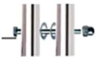
- 2 bolts M6x40.
-
2 bolts M6x65.
-
4 Cap nuts M6.
- 2 rings M6.
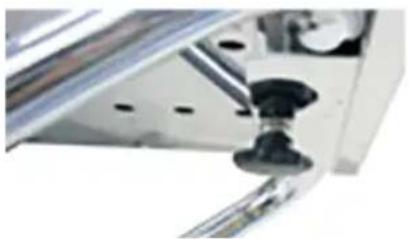
- 1 star bolt M6
Assembly
- Remove all protective plastic foil
- Fasten the frame with the already assembled wheels to the under part of the Power grill. Use
the parts delivered; M6x40 bolts and the M6 cap nuts. Take note of the frame stand, the bend in this frame has to be slightly bent upwards at the ends.
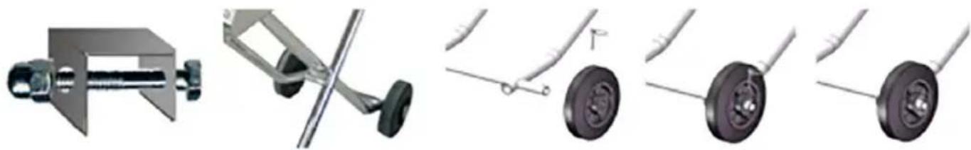
- Assemble the body frame the wheel frame. Take note, the supplied rings has to be positioned in the inner side of the frame and also where the
two frames join together. Use the long M6 x 65 bolts and the M6 cap nuts.
- Fasten the U-shaped part to the under part of the body frame. Use the star bolt supplied. Check if it's really tightened.
- Put the barbecue in up right position. The barbecue has to be positioned horizontally. If not the wheel frame has to be turned the other way round.
Warranty
Any defect affecting the functionality of the appliance which becomes apparent within one year after purchase will be repaired by free repair or replacement provided the appliance has been used and maintained in accordance with the instructions and has not been abused or misused in any way. Your statutory rights are not affected. If the appliance is claimed under warranty, state where and when it was purchased and include proof of purchase (e.g. receipt).
In line with our policy of continuous product development we reserve the right to change the product, packaging and documentation specifications without notice.
Discarding & Environment
When decommissioning the appliance, the product must not be disposed of with other household waste. Instead, it is your responsibility to dispose to your waste equipment by handing it over to a designated collection point. Failure to follow this rule may be penalized in accordance with applicable regulations on waste disposal. The separate collection and recycling of your waste equipment at the time of disposal will help conserve natural resources and ensure that it is recycled in a manner that protects human health and the environment.
For more information about where you can drop off your waste for recycling, please contact your local waste collection company. The manufacturers and importers do not take responsibility for recycling, treatment and ecological disposal, either directly or through a public system.
1 = Haupthahn
2 = Druckregler
3 = Gasschlauch
4 = Gasflasche
5 = Gummischeibe
1 = Hoofdkraan
2 = Drukregelaar
3 = Gasslang
4 = Gasfles
5 = Rubberen afdichtring
1 = Robinet principal
RO
1 = Κεντρική Βρύση
- Rám telesa namontujte na rám s kolieskami. Dodané podložky musia byl vložené vo vnútri rámu a
1 = Glavna slavina
2 = Regulator tlaka
3 = Crijevo za plin
4 = Plinska boca
5 = Gumena podloška
Hendi Romania S.R.L.
PKS Hendi South East Europe SA
5 Metsovou Str.
18346 Moschato, Athens, Greece
Tel: +30 210 4839700
Email: info@pks-hendi.com
Hendi Italia S.R.L.
Via Leonardo da Vinci 4
39100 Bolzano (BZ), Italy
Tel: +39 800 727 438
Email: office.italy@hendi.eu
Hendi HK Ltd.
1208, 12/F Exchange Tower
33 Wang Chiu Road, Kowloon Bay, Hong Kong
Tel: +852 2154 2618
Email: info-hk@hendi.eu
Find Hendi on internet:
www.hendi.com
www.facebook.com/HendiToolsforChefs
https://www.linkedin.com/company/hendi-tools-for-chefs/
www.youtube.com/HendiEquipment
- Changes, printing and typesetting errors reserved.
- SAFETY REGULATIONS
- SPECIAL SAFETY INSTRUCTIONS
- INTENDED USE
- CONNECTING THE GAS BOTTLE
- CHECK THE CONNECTIONS FOR LEAKS USING A SOAP AND WATER SOLUTION
- IGNITING THE GAS BARBECUE
- EXTINGUISHING THE GAS BARBECUE
- CLEANING AND MAINTENANCE
- IF IN DOUBT, PLEASE CONTACT YOUR SUPPLIER
- NOTE
- ASSEMBLING THE UNDERCARRIAGE
- ASSEMBLY
- WARRANTY
- DISCARDING & ENVIRONMENT
- HENDI ROMANIA S.R.L
- PKS HENDI SOUTH EAST EUROPE SA
- HENDI ITALIA S.R.L
- HENDI HK LTD
- FIND HENDI ON INTERNET
Brand : Hendi
Model : 148105
Category : Barbecue