JetInox 112 M - Water pump DAB - Free user manual and instructions
Find the device manual for free JetInox 112 M DAB in PDF.
| Product type | Self-priming centrifugal pump |
| Brand | DAB |
| Model | JetInox 112 M |
| Applications | Domestic water supply, agriculture, gardening, industrial services |
| Pumped liquids | Clean water without solid bodies or abrasives, non-chemically aggressive |
| Maximum flow rate | 4,8 m³/h |
| Maximum suction height | Up to 9 m |
| Power supply voltage | Single-phase 220-240V 50Hz / 110V 50Hz / 115V 60Hz / 230V 60Hz; Three-phase 230V 3~ 400V 3~ 50/60Hz |
| Power consumption | See electrical data plate |
| Motor protection degree | IP44 |
| Terminal board protection degree | IP55 |
| Motor insulation class | F |
| Maximum liquid temperature | 0°C to +40°C |
| Maximum service pressure | 0,8 MPa (8 bar) |
| Weight | Indicated on the packaging label |
| Dry running | Prohibited, risk of irreparable damage to mechanical seal |
| Maximum starts per hour | 20 |
| Maintenance and cleaning | Rinse with clean water before installation; maintenance by qualified personnel after disconnection |
| Safety | Use a 30 mA residual current circuit breaker for fountains; comply with electrical standards |
| Spare parts and repairability | Replaceable power cable (type H05 RN-F or H07 RN-F); manufacturer spare parts |
Frequently Asked Questions - JetInox 112 M DAB
User questions about JetInox 112 M DAB
0 question about this device. Answer the ones you know or ask your own.
Ask a new question about this device
Download the instructions for your Water pump in PDF format for free! Find your manual JetInox 112 M - DAB and take your electronic device back in hand. On this page are published all the documents necessary for the use of your device. JetInox 112 M by DAB.
USER MANUAL JetInox 112 M DAB
ISTRUZIONI PER L'INSTALLAZIONE E LA MANUTENZIONE (IT)
INSTRUCTIONS FOR INSTALLATION AND MAINTENANCE (GB)
INSTRUCTIONS DE MISE EN SERVICE ET D'ENTRETIEN (FR)
INSTALLATIONSANWEISUNG UND WARTUNG (DE)
INSTRUCTIES VOOR INGEBRUIKNAME EN ONDERHOUD (NL)
INSTRUCCIONES PARA LA INSTALACION Y EL MANTENIMIENTO (ES)
INSTALLATIONS - OCH UNDERHÄLLSANVISNING (SE)
ΟΔΗΓΙΕΣ ΓΙΑ ΤΗΝ ΕΓΚΑΤΑΣΤΑΣΗ ΚΑΙ ΣΥΝΤΗΡΗΣΗ (GR)
KULLANIM VE BAKIM TALİMATLARI (TR)
POKYNY K INSTALÁCII A ÚDRŽBE (SK)
ИНСТРУКЦИИ ПО МОНТАЖУ И ТЕХНИЧЕСКОМУ ОБСЛУЖИВАНИЮ (RU)
MONTAVIMO IR PRIEŽIŪROS INSTRUKCIJA (LT)
إرشادات للتركيب والعناية.
INSTRUÇÕES PARA A INSTALAÇÃO E A MANUTENÇÃO (PT)
ASENNUS- JA HUOLTO-OHJEET (FI)
NÁVOD NA POUŽITÍ A ÚDRŽBU (CZ)
INSTRUKCJA MONTAŻU I KONSERWACJI (PL)
ИНСТРУКЦИЯ ЗА ТЕХНИЧЕСКА ЕКСПЛОАТАЦИЯ (BG)
INSTRUCTIUNI PENTRU INSTALARE SI INTRETINERE (RO)
UPUTSTVO ZA RUKOVANJE (RS)
INSTALLÁCIÓS ÉS KARBANTARTÁSI UTASÍTÁS (HU)
NAVODILA ZA INŠTALACIJO IN VZDRŽEVANJE (SI)
NSTRUKTIONER VEDR∅RENDE INSTALLATION OG VEDLIGEHOLDELSE (DK)
UZSTÄDİŞANAS UN TEHNISKÄS APKOPES ROKASGRÄMATA (LV)
ІНСТРУКЦІЇ З МОНТАЖУ ТА ТЕХНІЧНОГО ОБСЛУГОВУВАННЯ (UA)
JET
JETINOX
JETCOM
AQUAJET
AQUAJETINOX
AQUAJETCOM
GARDEN-JET
GARDEN-INOX
GARDEN-COM

JET 62 - JET 82 - JET 92 - JET 102 - JET 112 - JET 132
JETINOX 62 - JETINOX 82 - JETINOX 92 - JETINOX 102 - JETINOX 112 - JETINOX 132
JETCOM 62 - JETCOM 82 - JETCOM 92 - JETCOM 102 - JETCOM 132
AQUAJET 82 - AQUAJET 92 - AQUAJET 102 - AQUAJET 112 - AQUAJET 132 -
AQUAJETINOX 82 - AQUAJETINOX 92 - AQUAJETINOX 102 - AQUAJETINOX 112 - AQUAJETINOX 132
AQUAJETCOM 62 - AQUAJETCOM 82 - AQUAJETCOM 92 - AQUAJETCOM 102
GARDEN-JET 82 – GARDEN-JET 92 – GARDEN-JET 102 – GARDEN-JET 132
GARDEN-INOX 82 - GARDEN-INOX 92 - GARDEN-INOX 102 - GARDEN-INOX 132
GARDEN-COM 62 - GARDEN-COM 82 - GARDEN-COM 102
| ITALIANO | pag | 01 |
| ENGLISH | page | 04 |
| FRANÇAIS | page | 07 |
| DEUTSCH | Seite | 10 |
| NEDERLANDS | bladz | 13 |
| ESPAÑOL | pág | 16 |
| SVENSKA | sid | 19 |
| ΕΛΛΗΝΙΚΑ | σελ. | 22 |
| TÜRKÇE | sayfa | 25 |
| SLOVENSKY | str. | 28 |
| PYССКИЙ | стр. | 31 |
| LIETUVIŠKAI | psl. | 34 |
| 37 عspecies صفحة | ||
| PORTUGUÊS | pág. | 41 |
| SUOMI | sivu | 44 |
| ČESKY | strana | 47 |
| POLSKI | str. | 50 |
| БЪЛГАРСКИ | страница | 53 |
| ROMANA | pag. | 56 |
| SRPSKI | str. | 59 |
| MAGYAR | oldal | 62 |
| SLOVENŠČINA | str. | 65 |
| DANSK | side | 68 |
| LATVISKI | lpp. | 71 |
| УКРАЇНСЬКА | стор. | 74 |
Self priming centrifugal pump (until 9m) with excellent suction capacity even in the presence of air bubbles. Suitable for pumping water with low levels of sandy impurities. Especially used in domestic water supply installations. Suitable for small farms and gardening, small scale industrial services and where self priming is necessary.
1. PUMPED FLUIDS

The machine has been designed and built for pumping water, free from explosive substances and solid particles or fibres, with a density of 1000 kg/m^3 and a kinematic viscosity of 1 mm^2/s , and chemically non-aggressive liquids.
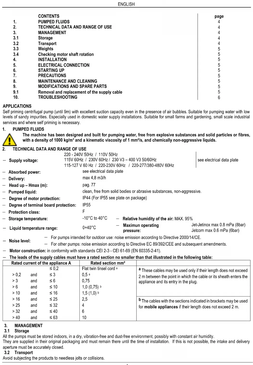
2. TECHNICAL DATA AND RANGE OF USE
| 220 - 240V 50Hz / 110V 50Hz | |||
| — Supply voltage: | 115V 60Hz / 230V 60Hz / 230 V3 – 400 V3 50/60Hz | see electrical data plate | |
| 115-127 V 60 Hz / 220-230V 60Hz / 220-277/380-480V 60Hz | |||
| — Absorbed power: | see electrical data plate | ||
| — Delivery: | max 4,8 m3/h | ||
| — Head up – Hmax (m): | pag. 77 | ||
| — Pumped liquid: | clean, free from solid bodies or abrasive substances, non-aggressive. | ||
| — Degree of motor protection: | IP44 (For IP55 see plate on package) | ||
| — Degree of terminal board protection: | IP55 | ||
| — Protection class: | F | ||
| — Storage temperature: | -10°C to 40°C | — Relative humidity of the air: MAX. 95% | |
| — Liquid temperature range: | 0+40°C | — Maximun operating pressure: | Jet-Jetinox max 0.8 mPa (8bar) Jetcom max 0.6 mPa (6bar) |
— For pumps intended for outdoor use: noise emission according to Directive 2000/14/CE.
— Noise level.
— For other pumps: noise emission according to Directive EC 89/392/CEE and subsequent amendments.
— Motor construction: in conformity with standards CEI 2-3 - CEI 61-69 (EN 60335-2-41).
— The leads of the supply cables must have a rated section no smaller than that illustrated in the following table:
| Rated current of the appliance A | Rated section mm^2 | |||
| ≤ 0,2 | Flat twin tinsel cord^a | ^a These cables may be used only if their length does not exceed 2 m between the point in which the cable or its sheath enters the appliance and its entry in the plug. | ||
| >0,2 | and | ≤ 3 | 0,5^a | |
| >3 | and | ≤ 6 | 0,75 | |
| >6 | and | ≤ 10 | 1,0 (0,75)^b | |
| >10 | and | ≤ 16 | 1,5 (1,0)^b | |
| >16 | and | ≤ 25 | 2,5 | ^b The cables with the sections indicated in brackets may be used for mobile appliances if their length does not exceed 2 m. |
| >25 | and | ≤ 32 | 4 | |
| >32 | and | ≤ 40 | 6 | |
| >40 | and | ≤ 63 | 10 | |
3. MANAGEMENT
3.1 Storage
All the pumps must be stored indoors, in a dry, vibration-free and dust-free environment, possibly with constant air humidity.
They are supplied in their original packaging and must remain there until the time of installation. If this is not possible, the intake and delivery aperture must be accurately closed.
3.2 Transport
Avoid subjecting the products to needless jolts or collisions.
To lift and transport the unit, use lifting equipment and the pallet supplied standard (if applicable).
3.3 Weights
The adhesive label on the package indicates the total weight of the electropump.
3.4 Checking motor shaft rotation
Before installing the pump you must check that the rotating parts turn freely. For this purpose remove the fan cover from its seat in the motor end cover. Insert a screwdriver in the notch on the motor shaft from the ventilation side. If there is a blockage, turn the screwdriver, tapping it gently with a hammer. FIG. A
4. INSTALLATION

The pumps may contain small quantities of residual water from testing.
We advise flushing them briefly with clean water before their final installation.
4.1 The electropump must be fitted in a well ventilated place, protected from unfavourable weather conditions and with an environment temperature not exceeding 40^ C. Fig.B
4.2 A firm anchoring of the pump to the bearing surface favours the absorption of any vibrations caused by pump operation. Fig. C
4.3 Ensure that the metal pipes do not exert undue strain on the apertures, thus preventing deformations or breakages. Fig. C
4.4 The lifting and carrying handle must always be present and well fixed to the support on all pumps produced in the portable version.
4.5 Pumps that are to be used in fountains for outdoor use, in garden ponds and similar places, must be fed by means of a circuit equipped with a differential current device, the rated operating differential current of which is not higher than 30 mA.
5. ELECTRICAL CONNECTION
Caution! always follow the safety regulations.

Scrupulously follow the wiring diagrams inside the terminal board box.
5.1 In fixed installations, International Safety Standards require the use of isolating switches with a fuse-carrier base.
5.2 Single-phase motors are provided with built-in thermal overload protection and may be connected directly to the mains. Three-phase motors must be protected with an automatic switch (e.g. overload protection) set at the values on the electropump data plate.
5.3 In the power mains there must be a device that ensures complete disconnection in overvoltage category III conditions.
6. STARTING UP
6.1

Do not start the pump unless it has been completely filled with fluid.
Before starting up, check that the pump is properly primed; fill it completely with clean water by means of the hole provided after having removed the filler cap on the pump body (Fig. F). Dry operation causes irreparable damage to the mechanical seal. The filling cap must then be screwed back on carefully.
6.2 Switch on the power and check, on the three-phase version, that the motor is turning in the correct direction; this should be in a clockwise direction, looking at the motor from the impeller side. Fig. G If it is turning in the wrong direction, invert the connections of any two wires on the terminal board, after having disconnected the pump from the power mains.
7. PRECAUTIONS
7.1 The electropump should not be started more than 20 times in one hour so as not to subject the motor to excessive thermal shock.
7.2 When starting after long periods of inactivity, the starting-up operations listed above must be repeated.
7.3 It is always good practice to place the pump as close as possible to the liquid to be pumped (Fig.1 - Pag.74)
8. MAINTENANCE AND CLEANING

The electropump must not be dismantled unless by skilled personnel in possession of the qualifications required by the regulations in force. In any case, all repairs and maintenance jobs must be carried out only after having disconnected the pump from the power mains.
9. MODIFICATIONS AND SPARE PARTS

Any modification not authorized beforehand relieves the manufacturer of all responsibility.

In the event of damage to the power cable of this appliance, the repair must be carried out by skilled personnel, in order to prevent all risks.
9.1 Removal and replacement of the supply cable
Before starting, ensure that the electropump is not connected to the power network.
For versions without a pressure switch: Remove the condenser cover, unscrewing the four screws on it. Unscrew the three terminals L - N - and disconnect the brown lead, the blue lead and the yellow-green lead, coming from the supply cable, after having slackened the grommet.
Version with a TELEMECANIQUE / SQUARE D - TELEMECANIQUE / ITALTECNICA pressure switch:
- Section of cable with plug from the pressure switch: unscrew the screw from the cover of the pressure switch using a screwdriver and remove the cover, releasing it from the base of the pressure switch. Slip out the yellow-green lead, unscrewing the earth screw on the left side. Still on the same side, slip the blue lead and the brown lead off their terminals, slackening the screws on the terminals. Slacken the cable clamping nut of the pressure switch on the left side and slip off the cable which is now disconnected.
— Section of cable from the pressure switch to the terminal board: unscrew the nut on the cover of the pressure switch using a screwdriver and remove the cover, releasing it from the base of the pressure switch. Slip out the yellow-green lead, unscrewing the earth screw on the
right side. Still on the same side, slip the blue lead and the brown lead off their terminals, slackening the screws on the terminals. Slacken the cable clamping nut of the pressure switch on the right side and slip off the cable which is now disconnected. Remove the terminal board cover, unscrewing the four screws on it. Unscrew the three terminals L - N - ⏻ and disconnect the brown lead, the blue lead and the yellow-green lead, coming from the supply pressure switch, after having slackened the grommet.
When replacing the power cable, a cable of the same type must be used (e.g. H05 RN-F or H07 RN-F depending on the installation) and with the same terminals, proceeding as for disassembly in inverse order.
ATTENTION: depending on the installation and if the pumps have no cable, fit supply cables type H05 RN-F for indoor use and type H07 RN-F for outdoor use, complete with plug (EN 60335-2-41). For power cables without a plug, provide a device for cutting off the mains (e.g. magnetothermal device) with separating contacts of at least 3 mm for each pole.
- TROUBLESHOOTING
| FAUL | CHECKS (possible cause) | REMEDY |
| 1. The motor does not start and makes no noise. | A. Check the electric connections.B. Check that the motor is live.C. Check the protection fuses. | C. If they are burnt-out, change them.N.B. If the fault is repeated immediately this means that the motor is short circuiting. |
| 2. The motor does not start but makes noise. | A. Ensure that the mains voltage is the same as the value on the plate.B. Ensure that the connections have been made correctly.C. Check that all the phases are present on the terminal board. (3~)D. Look for possible blockages in the pump or motor.E. Check the condition of the capacitor. | B. Correct any errors.C. If not, restore the missing phase.D. Remove the blockage.E. Replace the capacitor. |
| 3. The motor turns with difficulty. | A. Check the voltage which may be insufficient.B. Check whether any moving parts are scraping against fixed parts. | B. Eliminate the cause of the scraping. |
| 4. The pump does not deliver. | A. The pump has not been primed correctly.B. On three-phase motors, check that the direction of rotation is correct.C. The diameter of the intake pipe is insufficient.D. Blocked foot valve. | B. If necessary, invert the connection of two supply wiresC. Replace the pipe with one with a larger diameter.D. Clean the foot valve. |
| 5. The pump does not prime. | A. The intake pipe or the foot valve is taking in air.B. The downward slope of the intake pipe favours the formation of air pockets. | A. Eliminate the phenomenon and prime again.B. Correct the inclination of the intake pipe. |
| 6. The pump supplies insufficient flow. | A. Blocked foot valve.B. The impeller is worn or blocked.C. The diameter of the intake pipe is insufficient.D. On three-phase motors, check that the direction of rotation is correct. | A. Clean the foot valve.B. Remove the obstructions or replace the worn parts.C. Replace the pipe with one with a larger diameter.D. If necessary, invert the connection of two supply wires. |
| 7. The pump vibrates and operates noisily. | A. Check that the pump and the pipes are firmly anchored.B. There is cavitation in the pump, that is the demand for water is higher than it is able to pump.C. The pump is running above its plate characteristics. | A. Fix the loose parts more carefully.B. Reduce the intake height or check for load losses.C. It may be useful to limit the flow at delivery. |
1.6 Equipment styling maintenance calibration and timing of the task.
5. CONEXIUNI ELECTRICE:
Respectati intotdeauna normele de siguranta!

Respectati in mod riguros schemele electrice descrise in interiorul cutiei de borne.
5.1 In instalatiile fixe, Normele Internationale prevad folosirea intrerupatoarelor prevazute cu sigurante fuzibile.
natural_image
Diagram of a hydraulic system with a pump and motor, showing fluid flow and structural components (no text or labels)DAB PUMPS LTD.
6 Gilbert Court
Newcomen Way
Severalls Business Park
Colchester
Essex
C04 9WN - UK
salesuk@dwtgroup.com
Tel. +44 0333 777 5010
DAB PUMPS BV
'tHofveld 6 C1
info.belgium@dwtgroup.com
Tel. +32 2 4668353
DAB PUMPS INC.
3226 Benchmark Drive
Ladson, SC 29456 - USA
info.usa@dwtgroup.com
Tel. 1-843-797-5002
Fax 1-843-797-3366
000 DAB PUMPS
Novgorodskaya str. 1, block G
office 308, 127247, Moscow - Russia
info.russia@dwtgroup.com
Tel. +7 495 122 0035
Fax +7 495 122 0036
DAB PUMPS POLAND SP. z.o.o.
No.40 Kaituo Road, Qingdao Economic &
Technological Development Zone
Qingdao City, Shandong Province - China
PC: 266500
sales.cn@dwtgroup.com
Tel. +86 400 186 8280
Fax +86 53286812210
DAB PUMPS IBERICA S.L.
Calle Verano 18-20-22
28850 - Torrejón de Ardoz - Madrid
Spain
Info.spain@dwtgroup.com
Tel. +34 91 6569545
Fax: + 34 91 6569676
DAB PUMPS B.V.
Twenty One industrial Estate,
16 Purlin Street, Unit B, Warehouse 4
Olifantsfontein - 1666 - South Africa
info.sa@dwtgroup.com
Tel. +27 12 361 3997
info.germany@dwtgroup.com
Tel. +49 2151 82136-0
Fax +49 2151 82136-36
DAB PUMPS HUNGARY KFT.
H-8800
Nagykanizsa, Buda Ernő u.5
Hungary
Tel. +36 93501700
426 South Gippsland Hwy,
Dandenong South VIC 3175 – Australia
info.oceania@dwtgroup.com
Tel. +61 1300 373 677

DAB PUMPS S.p.A.
Via M. Polo, 14 - 35035 Mestrino (PD) - Italy
Tel. +39 049 5125000 - Fax +39 049 5125950
www.dabpumps.com