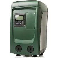
Esybox Mini 3 - Water pump DAB - Free user manual and instructions
Find the device manual for free Esybox Mini 3 DAB in PDF.


| Product type | Water pump with built-in inverter, expansion tank and automatic start |
| Brand | DAB |
| Model | Esybox Mini 3 |
| Power supply | Single phase 220-240 V / 110-127 V, 50/60 Hz |
| Maximum power | 850 W |
| Dimensions (L x W x H) | 445 x 262 x 242 mm (without feet) |
| Weight (empty) | 14 kg |
| Protection class | IP X4 |
| Motor insulation class | F |
| Maximum head | 55 m |
| Maximum flow rate | 80 l/min |
| Maximum working pressure | 7.5 bar |
| Maximum liquid temperature | 40 °C |
| Maximum ambient temperature | 50 °C |
| Suction capacity | Up to 8 m (depth) |
| Built-in expansion tank | 1 liter, pre-charged to 2.0 bar |
| Main functions | Constant pressure, dry run protection, anti-freeze, anti-cycling, anti-blocking |
| Connectivity | Wi-Fi, Bluetooth via DConnect APP, DConnect Cloud |
| Installation type | Vertical or horizontal, floor or wall-mounted (optional kit) |
| Maintenance | Clean non-return valve, check tank pressure, release motor shaft if necessary |
| Warranty | According to local legislation, covers manufacturing defects |
Frequently Asked Questions - Esybox Mini 3 DAB
User questions about Esybox Mini 3 DAB
0 question about this device. Answer the ones you know or ask your own.
Ask a new question about this device
Download the instructions for your Water pump in PDF format for free! Find your manual Esybox Mini 3 - DAB and take your electronic device back in hand. On this page are published all the documents necessary for the use of your device. Esybox Mini 3 by DAB.
USER MANUAL Esybox Mini 3 DAB
INSTRUCTIONS FOR INSTALLATION AND MAINTENANCE (GB) INSTRUCTIONS POUR L'INSTALLATION ET LA MAINTENANCE (FR)
esybox mini ^3
Manual valid for firmware versions 2.x.y-4.x-1.x
1.1 Applications ......37
1.2 Description of the Integrated Inverter....38
1.3 Integrated Expansion Vessel....38
1.4 Technical characteristics....39
2. INSTALLATION....39
2.1 - Vertical Configuration....40
2.1.1 Hydraulic connections 40
2.1.2. Loading Operation - Installation above head and below head 41
2.2 - Horizontal Configuration 41
2.2.1 Hydraulic connections 41
2.2.2 Orientation of the Interface Panel 42
2.2.3 Loading Operation - Installation above head and below head 42
3. COMMISSIONING 42
3.1 Electrical Connections....42
3.2 Configuration of the Integrated Inverter 43
3.3 - Priming....43
4. THE KEYPAD AND THE DISPLAY 44
4.1 Direct Access with a Combination of Keys....45
4.2 - Access by name with a drop-down menu....46
4.3 - Structure of the menu pages. (FIRMWARE VERSION ≤ 4.x.x)....47
4.4 - Structure of the menu pages. (FIRMWARE VERSION ≥ 4.x.x)....48
4.5 - Blocking parameter setting by Password....49
4.6 - Enabling and disabling the motor 49
5. MEANING OF THE INDIVIDUAL PARAMETERS ....49
5.1 User Menu 49
5.1.1 – Status ....49
5.1.2 - RS: Rotation speed display....49
5.1.3 - VP: Pressure display....50
5.1.4 - VF: Flow display 50
5.1.5 - PO: Absorbed power display 50
5.1.6 - C1: Phase current display 50
5.1.7 - SV: Supply voltage 50
5.1.8 - SR: Supply range 50
5.1.9 - TE: Dissipator temperature display 50
5.1.10- PKm: Pressure measured at intake....50
5.1.11 - Operating hours and number of starts....50
5.1.12 - PI: Power histogram....50
5.1.13 - Output flow meter 50
5.1.14 - NT: Display of network configuration ^(2) 50
5.1.15 - VE: Version Display....50
5.1.16 - FF: Fault & Warning display (Log)....50
5.2 - Monitor Menu ....51
5.2.1 - CT: Display contrast....51
5.2.2 - BK: Display brightness....51
5.2.3 - TK: Backlight switch-on time....51
5.2.4 - LA: Language 51
5.2.5 - TE: Dissipator temperature display 51
5.3 - Setpoint Menu .... 51
5.3.1 - SP: Setting the setpoint pressure....51
5.4 - Manual Menu....51
5.4.1 - Status 52
5.4.2 - RI: Speed setting....52
5.4.3 - VP: Pressure display....52
5.4.4 - VF: Flow display 52
5.4.5 - PO: Absorbed power display 52
5.4.6 - C1: Phase current display 52
5.4.7 - RS: Rotation speed display....52
5.4.8 - SV: Supply voltage 52
5.4.9 - SR: Supply range 52
5.4.10 - TE: Dissipator temperature display 52
5.5 - Installer Menu....52
ENGLISH
5.5.1 - RP: Setting the pressure fall to restart ....52
5.5.2 - OD: Type of plant 52
5.5.3 - MS: Measuring system....53
5.5.5 - EK: Setting the low pressure function on suction 53
5.5.6 - PK: Low pressure threshold on suction....53
5.5.7 - T1: Low pressure delay (function detecting low pressure on suction)....53
5.6 - Technical Assistance Menu....53
5.6.1 - TB: Water lack blockage time 53
5.6.2 - T2: Delay in switching off....53
5.6.3 - GP: Proportional gain coefficient....53
5.6.4 - GI: Integral gain coefficient....54
5.6.5 - RM: Maximum speed 54
5.6.6 - AY: Anti Cycling....54
5.6.7 - AE: Enabling the anti-block function....54
5.6.8 - AF: Enabling the anti-freeze function ....54
5.7- Setting low pressure detection on suction (typically used in boosting systemsconnected to the water mains)....54
5.8 - RF: Fault and warning reset ....54
5.8.1 - PW: Change password ....54
- PROTECTION SYSTEMS....54
6.1 - Description of blockages....55
6.1.1 - "BL" Anti Dry-Run (Protection against dry running)....55
6.1.2 - Anti-Cycling (Protection against continuous cycles without utility request)....55
6.1.3 - Anti-Freeze (Protection against freezing of water in the system) 55
6.1.4 - "BP1" Blockage due to fault of the delivery pressure sensor (system pressurisation)....56
6.1.5 - "BP2" Blockage due to fault of the suction pressure sensor 56
6.1.6 - "PB" Blockage due to supply voltage outside specifications....56
6.1.7 - "SC" Blockage due to short circuit between the motor phases....56
6.2 - Manual reset of error conditions....56
6.3 - Self-reset of error conditions....56
- RESET AND FACTORY SETTINGS....57
7.1 General system reset....57
7.2 Factory settings....57
7.3 Restoring the factory settings....57
- APP, DCONNECT CLOUD AND SOFTWARE UPDATE....58
8.1 - System requirements....58
8.2 - Updating the software....58
8.3 - Local updates via APP DCONNECT....58
- PARTICULAR INSTALLATIONS....61
9.1 - Inhibiting self-priming....61
9.2 - Wall installation 61
- MAINTENANCE....61
10.1 Accessory tool....62
10.2 - Emptying the system....62
10.3 - Non-return valve....62
10.4 - Motor shaft....63
- TROUBLESHOOTING....63
- UPDATING THE FIRMWARE....64
- DISPOSAL....64
- GUARANTEE....64
ENGLISH
KEY
The following symbols have been used in the discussion:

SITUATION OF GENERAL DANGER.
Failure to respect the instructions that follow may cause harm to persons and property.
SITUATION OF ELECTRIC SHOCK HAZARD.
Failure to respect the instructions that follow may cause a situation of grave risk for personal safety.
Notes and general information.
| Key | |
| K | Parameters available in version K. |
| DV | Parameters available only in version DV |
| * | Parameter not available for firmware version 3.xx |
| (1) | Applicable to firmware versions ≤4.x.x |
| (2) | Applicable to firmware versions ≥4.x.x |
WARNINGS
This manual refers to esybox mini ^4 .

Read this documentation carefully before installation.
Installation and operation must comply with the local safety regulations in force in the country in which the product is installed. Everything must be done in a workmanlike manner. Failure to respect the safety regulations not only causes risk to personal safety and damage to the equipment, but invalidates every right to assistance under guarantee.
The products dealt with in this discussion fall within the type of professional equipment and belong to insulation class 1.
Skilled personnel
The electrical and hydraulic connections may only be carried out by skilled personnel in possession of the technical qualifications required by the safety regulations in force in the country in which the product is installed.
The term skilled personnel means persons whose training, experience and instruction, as well as their knowledge of the respective standards and requirements for accident prevention and working conditions, have been approved by the person in charge of plant safety, authorizing them to perform all the necessary activities, during which they are able to recognize and avoid all dangers. (Definition for technical personnel IEC 364).
It is the responsibility of the installer to make sure that the power supply system is equipped with an efficient grounding system according to the regulations in force.
To improve immunity to possible noise radiating to other equipment, it is advisable to use separate wiring to power the inverter.
The appliance may be used by children over 8 years old and by persons with reduced physical, sensory or mental capacities, or who lack experience or knowledge, on condition that they are under supervision or after they have received instructions concerning the safe use of the appliance and the understanding of the dangers involved. Children must not play with the appliance. Cleaning and maintenance intended to be carried out by the user must not be performed by children without supervision.
Safety
Use is allowed only if the electric system is in possession of safety precautions in accordance with the regulations in force in the country where the product is installed (for Italy CEI 64/2).
Pumped liquids
The machine has been designed and made for pumping water, free from explosive substances and solid particles or fibres, with a density of 1000 Kg/m^3 , a kinematic viscosity of 1 mm^2/s and non chemically aggressive liquids.
ENGLISH

The power supply cable must never be used to carry or shift the pump.
Never pull on the cable to detach the plug from the socket.
If the power cable is damaged, it must be replaced by the manufacturer or by their authorised technical assistance service, so as to avoid any risk.
Failure to observe the warnings may create situations of risk for persons or property and will void the product guarantee.
RESPONSIBILITY

The Manufacturer does not vouch for correct operation of the electropumps or answer for any damage that they may cause if they have been tampered with, modified and/or run outside the recommended work range or in contrast with other indications given in this manual.
The Manufacturer declines all responsibility for possible errors in this instructions manual, if due to misprints or errors in copying. The Manufacturer reserves the right to make any modifications to products that it may consider necessary or useful, without affecting their essential characteristics.
1. GENERAL
The product is an integrated system composed mainly of a self-priming multi-stage centrifugal electropump, an electronic circuit that controls it and an expansion vessel. Cooling of the motor with water rather than air ensures less noise in the system.
1.1 Applications
Water systems supply and pressure boosting domestic use. On the outside the product appears as a parallelepiped that presents 6 faces as shown in Fig.1.
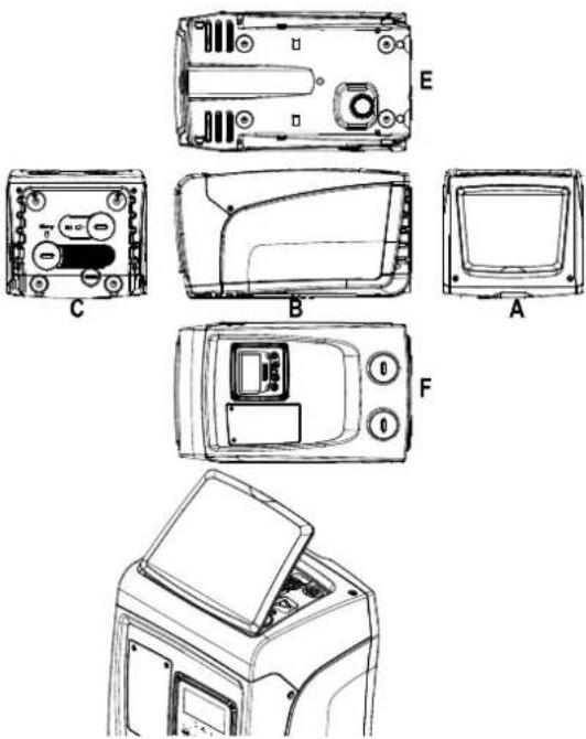
Figure 1
Face A: a door allows access to the Technical Compartment.
Figure 2
Inside the technical compartment you can access (see Fig.3):
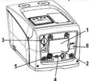
Figure 3
- Quick Guide;
- Technical data plate;
- Filling cap (only for vertical configuration);
- Accessory tool;
- Motor shaft;
- QR-code
Face B: A rubber cable gland allows the exit of the power cable to be connected to the power mains.
Face C: the 4 brass threads form the seat for the 4 support feet in the case of vertical installation. The two 1" screw caps can be removed to make the connections towards the system, depending on the installation configuration you want to adopt. If applicable, connect to the connection marked
ENGLISH
“IN” the system from which you want to draw water (well, cistern,...) and connect the delivery system to the connection marked “OUT”. There is also a ventilation grid. The 3/8” cap allows drainage of the system in the case of horizontal installation. There is also a ventilation grid.
Face E: the 4 brass threads form the seat for the 4 support feet in the case of horizontal installation. The main function of the 1" cap is drainage of the system in the case of vertical installation. There are also 2 ventilation grids.
Face F: as indicated by the label to be removed, the 1" cap next to the word "IN" on face C has a dual function: in the case of horizontal installation, the outlet that is closed by the cap acts as the system's loading door (see below "loading operations", par. 2.2.3); in the case of vertical installation, the same outlet can act as the input hydraulic connection (exactly like the one marked "IN" on face C and as an alternative to it). The other 1" cap gives access to a second delivery connection that can be used at the same time as or alternatively to the one indicated with "OUT" on face C. The user interface panel is composed of a display and a keyboard and its function is to set the system, query its status and communicate any alarms. The door closed by 2 screws gives access to a special maintenance compartment: cleaning of the non-return valve and resetting of the tank preload pressure.
The system can be installed in 2 different configurations: horizontal (Fig.4) or vertical (Fig.5).

natural_image
Line drawing of a portable electronic device with control panel and buttons (no text or symbols)Figure 4
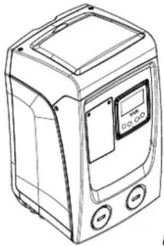
natural_image
Line drawing of a portable electronic device with control buttons and display (no text or symbols)Figure 5
1.2 Description of the Integrated Inverter
The electronic control integrated in the system is of the type with inverter and it makes use of flow, pressure and temperature sensors, also integrated in the system.
By means of these sensors the system switches on and off automatically according to the utility's needs and it is able to detect conditions of malfunction, to prevent and indicate them. The Inverter control ensures different functions, the most important of which, for pumping systems, are the maintaining of a constant pressure value in delivery and energy saving.
- The inverter is able to keep the pressure of a hydraulic circuit constant by varying the rotation speed of the electropump. In operation without an inverter the electropump is unable to modulate and, when there is an increase of the request for flow, the pressure necessarily decreases, or vice versa; this means the pressures are too high at low flow rates or too low when there is an increased request for flow.
- By varying the rotation speed according to the instantaneous request of the utility, the inverter limits the power supplied to the electropump to the minimum necessary to ensure that the request is satisfied. Instead, operation without an inverter contemplates operation of the electropump always and only at maximum power.
or the configuration of the parameters see chapters 4-5.
1.3 Integrated Expansion Vessel
The system is complete with an integrated expansion vessel with a total capacity of 1 litres. The main functions of the expansion vessel are:
• to make the system elastic so as to protect it against water hammer;
- to ensure a water reserve which, in the case of small leaks, maintains the pressure in the system for a longer time and spreads out needless restarts of the system which otherwise would be continuous;
- when the utility is turned on, ensure the water pressure for the seconds that the system takes to switch on and reach the correct rotation speed.
It is not a function of the integrated expansion vessel to ensure a water reserve such as to reduce interventions of the system (requests from the utility, not from a leak in the system). It is possible to add an expansion vessel with the capacity you prefer to the system, connecting it to a point on the delivery system (not a suction point!). In the case of horizontal installation it is possible to connect to the unused delivery outlet. When choosing the tank, consider that the quantity of water released will also depend on the parameters SP and RP that can be set on the system (chapters 4-5).
The expansion vessel is preloaded with pressurised air through the valve accessible from the special maintenance compartment (Fig.1, Face F).
The preload value with which the expansion vessel is supplied by the manufacturer is in agreement with the parameters SP and RP set as default, and anyway it satisfies the following equation:
- SP = Set Point (chapter 5.3.1) in bar
- RP = Reduction of pressure to restart (chapter 5.5.1) in bar
So, by the manufacturer: Pair = 3 - 0.3 - 0.7 = 2.0 bar
If different values are set for the parameters SP and/or RP, regulate the valve of the expansion vessel releasing or letting in air until the above equation is satisfied again (e.g.: SP=2.0bar; RP=0.3bar; release air from the expansion vessel until a pressure of 1.0 bar is reached on the valve).
ENGLISH

Failure to respect the above equation may lead to malfunctions of the system or to premature breakage of the diaphragm inside the expansion vessel.

Considering the expansion vessel capacity of only 1 litres, any operation to check the air pressure must be performed by connecting the pressure gauge very rapidly: on small volumes the loss of even a limited quantity of air can cause an appreciable drop in pressure. The quality of the expansion vessel ensures the maintenance of the set air pressure value, proceed to check it only at calibration or if you are sure of a malfunction.

Any operation to check and/or reset the air pressure must be performed with the delivery system not under pressure: disconnect the pump from the power supply and open the utility nearest to the pump, keeping it open until it no longer gives any water.

The special structure of the expansion vessel ensures its quantity and duration over time, especially of the diaphragm which is typically the component subject to wear for items of this type. However, in the case of breakage, the entire expansion vessel must be replaced and exclusively by authorised personnel.
1.4 Technical characteristics
| Topic | Parameter | Esybox mini3 | ||
| ELECTRIC POWER SUPPLY | Voltage* | 1x220-240 V | 1x230 V | 1x110-127 V |
| Frequency | 50/60 Hz | |||
| Maximum power | 850 W | |||
| Leakage current to earth | <2 mA | |||
| STRUCTURAL CHARACTERISTICS | Overall dimensions | 445x262x242 mm without feet support | ||
| Empty weight (excluding packaging) | 14 kg / 30,8 lb | |||
| Protection class | IP x4 | |||
| Insulation class of the | F | |||
| HYDRAULIC PERFORMANCE | Maximum head | 55 m / 180 ft | ||
| Maximum flow rate | 80 l/min / 21 U.S. GPM | |||
| Priming | <5min a 8m / 26 ft | |||
| Maximum working pressure | 7.5 bar / 109 psi | |||
| WORKING CONDITIONS | Max liquid temperature | 40 °C / 104 °F | ||
| Max environment temperature | 50 °C / 122 °F | |||
| Environment temperature of storage | -10÷60 °C / 14÷140 °F | |||
| Difference Ambient T. - Liquid T. | < 30 °C / 86 °F | |||
| Max. relative humidity | 50% | |||
| FUNCTIONALITY AND PROTECTIONS | Constant pressure | |||
| Protection against dry running | ||||
| Antifreeze protection | ||||
| Anticycling protection | ||||
| Motor overload protection | ||||
| Protection against abnormal supply voltages | ||||
| Protection against excess temperature | ||||
| *: refer to the technical plate on the pump | ||||
Tabel 1
2. INSTALLATION

The system is designed for indoor use: do not install the system outdoors and/or directly exposed to atmospheric agents.

The system is designed to be able to work in environments where the temperature remains between 1^ C and 50^ C (on condition that the electric power supply is ensured: see par. 5.6.8 “anti-freeze function”). Esybox mini operates correctly with a difference between ambient and liquid temperatures of no more than 30^ C (with the ambient temperature higher than the liquid temperature). Besides this temperature difference, the humidity limit must not exceed 50%, otherwise there is a risk of condensation forming, which can cause irreparable damage to the electronic board.
ENGLISH

The system is suitable for treating drinking water.
The system cannot be used to pump salt water, sewage, inflammable, corrosive or explosive liquids (e.g. petroleum, petrol, thinners), greases, oils or food productsi.
The system can suck up water with a level that does not exceed the depth of 8 m (he height between the water level and the pump suction mouth).
If the system is used for the domestic water supply, respect the local regulations of the authorities responsible for the management of water resources.
When choosing the installation site, check that:
- The voltage and frequency on the pump's technical data plate correspond to the values of the power supply system.
- The electrical connection is made in a dry place, far from any possible flooding.
• The earth system must comply with the regulations.
The possible presence of a small amount of water inside the product is a residue of the testing process.
If you are not sure of the absence of foreign bodies in the water to be pumped, install a filter on the system intake that is suitable for catching impurities.

The installation of a filter on intake causes a decrease of the system's hydraulic performance proportional to the loss of load caused by the filter itself (generally the greater the filtering power, the greater the fall in performance).
Choose the type of configuration you intend to use (vertical or horizontal) considering the connections to the system, the position of the user interface panel, and the spaces available according to the indications below. Wall installation is possible, see par. 8.2.
2.1 - Vertical Configuration
Screw the 4 rubber feet supplied loose in the package into the brass seats in face C. Put the system in place, taking into account the dimensions in Fig.6.
- The distance of at least 10mm between Face E of the system and any wall is obligatory to ensure ventilation through the grids provided. If you expect to have to drain the system from its discharge door and not from the system, leave a further distance sufficient to manoeuvre the drainage cap.
- The distance of at least 10mm between Face B of the system and an obstruction is obligatory to let out the power supply cable to the mains socket.
- The distance of at least 200mm between Face A of the system and an obstruction is recommended so as to be able to remove the door and gain access to the technical compartment.
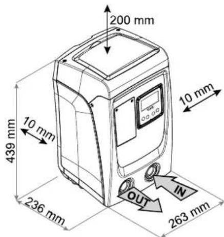
Figure 6
If the surface is not flat, unscrew the foot that is not touching and adjust its height until it contacts the surface so as to ensure the stability of the system. The system must in fact be placed in a safe and stable position, ensuring that its axis is vertical: it must not be in an inclined position.
2.1.1 Hydraulic connections
Make the connection at input to the system through the mouth on Face F marked "IN" in. Fig.6 (suction connection). Then remove the cap using a screwdriver.
Make the connection at output from the system through the mouth on Face F marked "OUT" in Fig.6 (delivery connection). Then remove the cap using a screwdriver.
All the hydraulic connections of the system to the plant to which it can be connected are of the threaded female type 1" GAS, made of brass.

If you intend to connect the product to the plant with fittings that have a diameter larger than the normal 1" pipe (for example the ring nut in the case of fittings in 3 pieces), make sure that the 1" Gas male thread of the coupling protrudes at least 25mm from the above diameter (see Fig.7)
ENGLISH
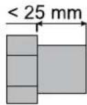

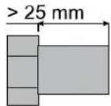

Figure 7

The brass threads are housed in technopolymer seats. When making the connection watertight by adding material (e.g. Teflon, hemp,...) ensure that the gasket is not too thick: under the action of an adequate tightening torque (e.g. long handled pipe wrench), the excess material could exert abnormal force on the technopolymer seat, damaging it irremediably.
With reference to its position with respect to the water to be pumped, the installation of the system may be defined "above head" or "below head". In particular the installation is defined "above head" when the pump is placed at a level higher than the water to be pumped (e.g. pump on the surface and water in a well); vice versa it is "below head" when the pump is placed at a level lower than the water to be pumped (e.g. overhead cistern and pump below).

If the vertical installation of the system is of the "over head" type, it is recommended to fit a non-return valve in the suction section of the system; this is to allow the operation of loading the system (par. 2.1.2).

If the installation is of the "over head" type, install the suction pipe from the water source to the pump in such a way as to avoid the formation of goosenecks or siphons. Do not place the suction pipe above the pump level (to avoid the formation of air bubbles in the suction pipe). The suction pipe must draw at its entrance at a depth of at least 30cm below the water level and must be watertight along its whole length, as far as the entrance to the electropump.

The suction and delivery pipes must be fitted so that they do not exert any mechanical pressure on the pump.
2.1.2. Loading Operation - Installation above head and below head
Installation "above head" (par. 2.1.1): access the technical compartment and, using a screwdriver, remove the filling cap (Fig.3). Fill the system with clean water through the loading door, taking care to let the air out. If the non-return valve on the suction pipe (recommended in paragraph 2.1.1) has been placed close to the system entry door, the quantity of water with which to fill the system should be 0,9 litres. It is recommended to fit the non-return valve at the end of the suction pipe (foot valve) so as to be able to fill it quickly too during the loading operation. In this case the quantity of water necessary for the loading operation will depend on the length of the suction pipe (0,9 litres + ...).
Installation "below head" (par. 2.1.1): if there are no check valves between the water deposit and the system (or if they are open), it loads automatically as soon as it is allowed to let out the trapped air. So slackening the filling cap (Fig.3) enough to vent the trapped air allows the system to load completely. You must survey the operation and close the loading door as soon as the water comes out (however it is recommended to fit a check valve in the section of the suction pipe and to use it to control the loading operation with the cap open). Alternatively, in the case where the suction pipe is intercepted by a closed valve, the loading operation may be carried out in a similar way to the one described for installation over head.
2.2 - Horizontal Configuration
Screw the 4 rubber feet supplied loose in the package into the brass seats in face E. Put the system in place, taking into account the dimensions in Fig.8.
- The distance of at least 10mm between Face B of the system and an obstruction is obligatory to let out the power supply cable to the mains socket.
- The distance of at least 200mm between Face A of the system and an obstruction is recommended so as to be able to remove the door and gain access to the technical compartment.

Figure 8
If the surface is not flat, unscrew the foot that is not touching and adjust its height until it contacts the surface so as to ensure the stability of the system. The system must in fact be placed in a safe and stable position, ensuring that its axis is vertical: it must not be in an inclined position.
2.2.1 Hydraulic connections
Make the connection at input to the system through the mouth on Face C marked "IN" in Fig. 8 (suction connection). Then remove the cap using a screwdriver. Make the connection at output from the system through the mouth on Face C marked "OUT 1" in Fig. 8 and/or through the mouth on Face F marked "OUT 2" in Fig. 8 (delivery connection).
In this configuration either of the 2 mouths can be used as an alternative to the other (depending on the convenience of the installation), or simultaneously (dual delivery system). Then remove the cap(s) from the door(s) you intend to use with a screwdriver.
All the hydraulic connections of the system to the plant to which it can be connected are of the threaded female type 1" GAS, made of brass.

See WARNING for Fig.7.
ENGLISH
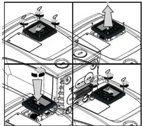
2.2.2 Orientation of the Interface Panel
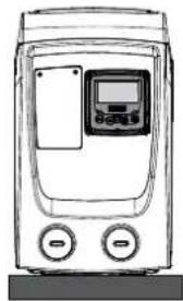
The Interface Panel has been designed so that it can be oriented in the direction where it is most convenient for the user to read: its square shape allows it to be rotated from 90^ to 90^ (Fig.9).
natural_image
Line drawing of a portable air conditioner unit with control panel and buttons (no text or symbols)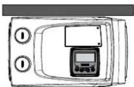
natural_image
Line drawing of a portable electronic device with control panel and two circular buttons (no text or symbols)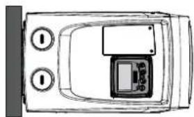
natural_image
Top-down schematic of a device casing with control buttons and display panel (no text or symbols)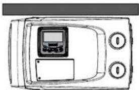
natural_image
Line drawing of a microwave oven with control panel and two buttons (no text or symbols)Figure 9
natural_image
Four-panel technical diagram showing mechanical assembly steps with no visible text or symbols- Disengage the 4 screws at the corners of the panel using the accessory tool.
- Do not remove the screws completely, just disengage them from the thread on the product body.
- Be careful not to drop the screws into the system.
- Move the panel away, taking care not to pull on the signal transmission cable.
- Reposition the panel in its seat at the preferred angle taking care not to pinch the cable.
Tighten the 4 screws with the wrench.
2.2.3 Loading Operation - Installation above head and below head
With reference to its position with respect to the water to be pumped, the installation of the system may be defined "above head" or "below head". In particular the installation is defined "above head" when the pump is placed at a level higher than the water to be pumped (e.g. pump on the surface and water in a well); vice versa it is "below head" when the pump is placed at a level lower than the water to be pumped (e.g. overhead cistern and pump below).
Installation “above head”: with a screwdriver, remove the filling cap which, for the horizontal configuration, is the one on Face F (Fig.1). Fill the system with clean water through the loading door, taking care to let the air out: to ensure optimum filling it is convenient to open also the loading door on Face A (Fig.1), used for filling in the vertical configuration, so as to let all the air out, which otherwise could remain trapped in the system; take care to close the openings correctly once the operation is completed. The quantity of water with which to fill the system must be at least 0,7 litri almeno. litres. It is recommended to fit a non-return valve at the end of the suction pipe (foot valve) so as to be able to fill it quickly too during the loading operation. In this case the quantity of water necessary for the loading operation will depend on the length of the suction pipe (0,7 litres + ...).
Installation "below head": if there are no check valves between the water deposit and the system (or if they are open), it loads automatically as soon as it is allowed to let out the trapped air. So slackening the filling cap (Face F - Fig.1) enough to vent the air allows the system to load completely. You must survey the operation and close the loading door as soon as the water comes out (however it is recommended to fit a check valve in the section of the suction pipe and to use it to control the loading operation with the cap loose). Alternatively, in the case where the suction pipe is intercepted by a closed valve, the loading operation may be carried out in a similar way to the one described for installation over head.
3. COMMISSIONING

The suction depth must not exceed 8 m.
3.1 Electrical Connections
To improve immunity to the possible noise radiated towards other appliances it is recommended to use a separate electrical duct to supply the product.

The line voltage may change when the electropump is started. The line voltage may undergo variations depending on other devices connected to it and on the quality of the line.

It is recommended to carry out installation as indicated in the manual, in compliance with the laws, directives and standards in force in the place of use and depending on the application.
The product contains an inverter inside which there are continuous voltages and currents with high-frequency components (see Table 2).
ENGLISH
| Type of possible fault currents to earth | ||||
| Alternating | Unipolar pulsed | Direct | With high-frequency components | |
| Inverter with single-phase power supply | √ | √ | √ | |
Table 2
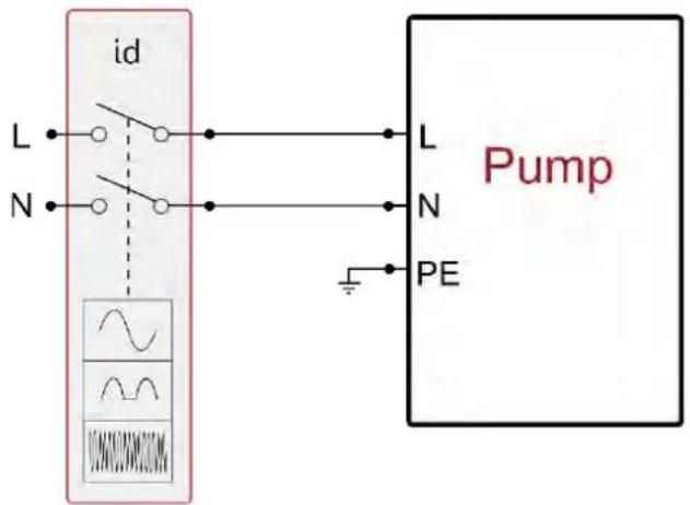
Fig 10 single-phase installation example
The thermal magnetic circuit breaker must be correctly sized (see Electrical Characteristics). For pumps not supplied with a plug, the correspondence of the colours of the leads is as indicated in Table 3:
| Connection | Type A | Type B |
| Phase | Brown | Brown |
| Neutral | Blue | Blue |
| Earth (EP) | Yellow/Green | Green |
| Type A: European markets or similar.Type B: American and Canadian markets or similar. | ||
Table 3
The appliance must be connected to a main switch that cuts off all the power supply poles. When the switch is in off position, the distance separating each contact must respect the indications in Table 4.
| Minimum distance between the contacts of the power switch | ||
| Power supply [V] | ≤127 | >127 and ≤240 |
| Minimum distance [mm] | >1,7 | >3 |
Table 4
3.2 Configuration of the Integrated Inverter
The system is configured by the manufacturer to satisfy most installation cases operating at constant pressure. The main parameters set in the factory are:
- Set-Point (desired value of constant pressure) SP = 2.7 bar / 39 psi.
• Reduction of pressure to restart RP = 0.3 bar / 4.3 psi. - Anti-cycling function: Disabilitata.
However, these parameters and others can be set by the user according to the system. See par. 4-5 for the specifications.

For the definition of the parameters SP and RP, the pressure at which the system starts has the value:
Pstart = SP - RP For example: 2.7 - 0.3 = 2.4 bar in the default configuration
The system does not work if the utility is at a height higher than the equivalent in metres of water column of the Pstart (consider 1 bar = 10 m water column): for the default configuration, if the utility is at a height of at least 27m the system does not start.
3.3 - Priming
The priming of a pump is the phase during which the machine attempts to fill the body and the suction pipe with water. If the operation is successful the machine can work regularly.
ENGLISH
Once the pump has been filled (par. 2.1.2, 2.2.3) and the device has been configured (par. 3.2), it is possible to connect the electric power supply after having opened at least one utility on delivery for the first 10 seconds.
If a flow of water is detected in delivery, the pump is primed and starts its regular work. This is the typical case of installation below head (par. 2.1.2, 2.2.3). The utility opened in delivery from which the pumped water is coming out can be closed.
If a regular flow in delivery is not detected after 10 seconds, the system asks for confirmation to enter the priming procedure (typical case of installation above head par. 2.1.2, 2.2.3). Or:
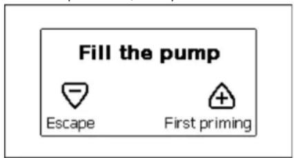
Figure 11.1: Priming PopUp ^(1)
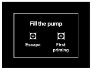
Figure 11.2: Priming PopUp (2)
When “A” is pressed the pump enters the priming procedure: it starts working for a maximum time of 5 minutes during which the safety block for dry operation is not tripped. The priming time depends on various parameters, the most influential of which are the depth of the water level from which it is drawing, the diameter of the suction pipe, the water-tightness of the suction pipe. On condition that a suction pipe is used that is no smaller than 1” and that it is well sealed (with no holes or joins from which it can take in air), the product has been studied to manage to prime in water conditions up to 8m in depth in a time of less than 5 minutes. As soon as the product detects a regular flow in delivery, it leaves the priming procedure and starts its regular work. The utility opened in delivery from which the pumped water is coming out can be closed. If after 5 minutes of the procedure the product is still not primed, the interface display sends a failure message. Disconnect the power supply, load the product adding new water, wait 10 minutes and repeat the procedure from the moment you put the plug in the socket.
Press "v" to confirm that you do not want to start the priming procedure. The product remains in alarm status.
Operation
Once the electropump is primed, the system starts regular operation according to the configured parameters: it starts automatically when the tap is turned on, supplies water at the set pressure (SP), keeps the pressure constant even when other taps are turned on, stops automatically after time T2 once the switching off conditions are reached (T2 can be set by the user, factory value 10 sec).
4. THE KEYPAD AND THE DISPLAY
The user interface is composed of a keypad with 320x240 pixel LCD display and with POWER, COMM, ALARM warning leds as can be seen in Fig.12.
The display shows the values and the statuses of the device, with indications on the functionality of the various parameters.
The functions of the keys are summed up in Table 5.
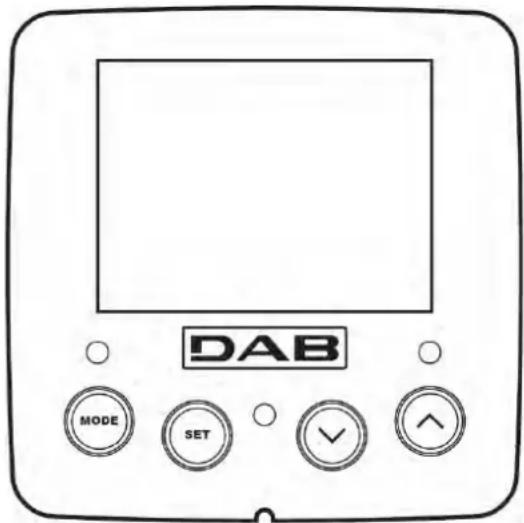
Figure 12
 | The MODE key allows you to move on to the next items in the same menu. Holding it down for at least 1 sec allows you to skip to previous menu item. |
 | The SET key allows you to leave the current menu. |
 | Decreases the current parameter (if it is an editable parameter). |
ENGLISH

Increases the current parameter (if it is an editable parameter).
Table 5
Holding down the “^” key or the “v” key allows the automatic increase/decrease of the parameter selected. After the “^” key or the “v” key has been held down for 3 seconds, the automatic increase/decrease speed increases.

When the ^ key or the v key is pressed the selected value is modified and saved immediately in the permanent memory (EEprom). If the machine is switched off, even accidentally, in this phase it does not cause the loss of the parameter that has just been set. The SET key is only for leaving the current menu and is not necessary for saving the changes made. Only in particular cases described in the following paragraphs are some values updated by pressing "SET" or "MODE".
Warning leds
- Power
White led. Lit with a fixed light when the machine is powered. Blinking when the machine is disabled. - Alarm
Red led. Lit with a fixed light when the machine is blocked by an error.
Menus
The complete structure of all the menus and of all the items of which they are composed is shown in Table 7.
Access to the menus
The various menus can be accessed from the main menu in two ways:
- Direct access with a combination of keys.
- Access by name with a drop-down menu.
4.1 Direct Access with a Combination of Keys
The desired menu can be accessed directly by pressing simultaneously the appropriate combination of keys for the required time (for example MODE SET to enter the Setpoint menu) and the various items in the menu are scrolled with the MODE key.
Table 6 shows the menus that can be reached with the combinations of keys.
| MENU NAME | DIRECT ACCESS KEYS | HOLD-DOWN TIME | |||
| User |  | On releasing the button | |||
| Monitor |  |  |  | 2 Sec | |
| Setpoint |  |  |  | 2 Sec | |
| Manual |  |  |  | 3 Sec | |
| Installer |  |  |  | 3 Sec | |
| Technical assistance |  |  |  | 3 Sec | |
| Reset factory values |  |  | 2 sec after switching on appliance | ||
| Reset |  |  |  |  | 2 Sec |
Table 6
ENGLISH
| Reduced menu (visible) | Extended menu (direct access or password) | |||||
| Main Menu | User Menu mode | Monitor Menu set-minus | Setpoint Menu mode-set | Manual Menu set-minus-plus | Installer Menu mode-set-minus | Tech. Assist. Menu mode-set-plus |
| MAIN (Main Page) | STATUS | CT Contrast | SP Setpoint pressure | STATUS | RP Decrease pressure for restart | TB Block time for water lack |
| Menu Selection | RS Revs per minute | BK Back lighting | RI Speed setting | OD Type of plant | T2 Delay in switching off | |
| VP Pressure | TK Backlighting switch on time | VP Pressure | MS Measuring system | GP Proportional gain. | ||
| VF Display of flow | LA Language | VF Display of flow | EK Enabling low pressure function on suction | GI Integral gain | ||
| PO Power absorbed by pump | TE Dissipator temperature | PO Power absorbed by pump | PK Low pressure threshold on suction | RM Maximum speed | ||
| C1 Pump phase current | C1 Pump phase current | T1 Low pr. delay | AY Anti Cycling | |||
| SV Supply voltage | RS Revs per minute | AE Anti-blocking | ||||
| SR Supply range | TE Dissipator temperature | AF AntiFreeze | ||||
| TE Dissipator temperature | SV Supply voltage | RF Reset faults and warnings | ||||
| PKm Pressure measured at in [13GCD] | SR Supply range | PW Modifica Password | ||||
Hours switched on Workin  Jrs Number of starts Jrs Number of starts | ||||||
| PI Power histogram | ||||||
Output flc  eter eter | ||||||
| VE Informatio [WZSH] / and SW | ||||||
FF  Fault & Warning (Log) Fault & Warning (Log) | ||||||
Table 7
4.2 - Access by name with a drop-down menu
The selection of the various menus is accessed by name. From the main menu you access menu selection by pressing either of the ^ or v keys. The names of the menus that can be accessed appear on the menu selection page and one of the menus is highlighted by a bar (see Fig. 13.1-13.2-14). Shift the highlighting bar using the ^ and v keys to select the menu you want and enter it by pressing MODE.
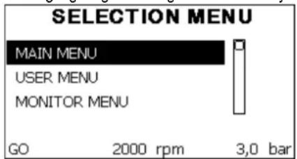
Figure 13.1: Drop-down menu (1)
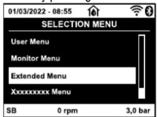
Figure 13.2: Drop-down menu (2)
The items available are MAIN, USER, MONITOR, followed by a fourth item, EXTENDED MENU; this item allows the number of menus displayed to be extended. When EXTENDED MENU is selected a pop-up appears asking you to type in an access key (PASSWORD). The access key
ENGLISH
(PASSWORD) coincides with the combination of keys used for direct access (as in Table 7) and allows the extended display of the menus from the menu corresponding to the access key to all those with a lower priority.
The order of the menus is: User, Manual Setpoint, Manual, Installer, Technical Assistance.
When an access key is selected, the menus released remain available for 15 minutes or until they are disabled manually by means of the item "Hide forward menus" which appears on the menu selection when using an access key.
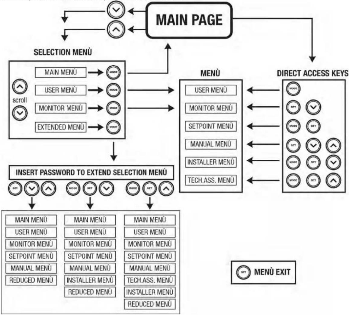
Fig. 14 shows an operating diagram for selecting the menus.
The menus are in the centre of the page, from the right you reach them by means of direct selection with a combination of keys, while from the left you reach them by means of the selection system with drop-down menu.
flowchart
graph TD
    A["MAIN PAGE"] --> B["SELECTION MENU"]
    B --> C["MAIN MENU"]
    B --> D["USER MENU"]
    B --> E["MONITOR MENU"]
    B --> F["EXTENDED MENU"]
    C --> G["MODE"]
    D --> H["MODE"]
    E --> I["MODE"]
    F --> J["MODE"]
    G --> K["INSERT PASSWORD TO EXTEND SELECTION MENU"]
    H --> K
    I --> K
    J --> K
    K --> L["SET"]
    K --> M["MODE"]
    K --> N["SET"]
    K --> O["MODE"]
    K --> P["SET"]
    K --> Q["MODE"]
    K --> R["SET"]
    K --> S["MODE"]
    K --> T["SET"]
    K --> U["MODE"]
    K --> V["SET"]
    K --> W["MODE"]
    K --> X["SET"]
    K --> Y["MODE"]
    K --> Z["SET"]
    K --> AA["MODE"]
    K --> AB["SET"]
    K --> AC["MODE"]
    K --> AD["SET"]
    K --> AE["MODE"]
    K --> AF["SET"]
    K --> AG["MODE"]
    K --> AH["SET"]
    K --> AI["MODE"]
    K --> AJ["SET"]
    K --> AK["MODE"]
    K --> AL["SET"]
    K --> AM["MODE"]
    K --> AN["SET"]
    K --> AO["MODE"]
    K --> AP["SET"]
    K --> AQ["MODE"]
    K --> AR["SET"]
    K --> AS["MODE"]
    K --> AT["SET"]
    K --> AU["MODE"]
    K --> AV["SET"]
    K --> AW["MODE"]
    K --> AX["SET"]
    K --> AY["MODE"]
    K --> AZ["SET"]
    K --> BA["MODE"]
    K --> BB["SET"]
    K --> BC["MODE"]
    K --> BD["SET"]
    K --> BE["MODE"]
    K --> BF["SET"]
    K --> BG["MODE"]
    K --> BH["SET"]
    K --> BI["MODE"]
    K --> BJ["SET"]
    K --> BK["MODE"]
    K --> BL["SET"]
    K --> BM["MODE"]
    K --> BN["SET"]
    K --> BO["MODE"]
    K --> BP["SET"]
    K --> BQ["MODE"]
    K --> BR["SET"]
    K --> BS["MODE"]
    K --> BT["SET"]
    K --> BU["MODE"]
    K --> BV["SET"]
    K --> BW["MODE"]
    K --> BX["SET"]
    K --> BY["MODE"]
    K --> BZ["MENÙ EXIT"]
Figure 14 Diagram of possible menu accesses
4.3 - Structure of the menu pages. (FIRMWARE VERSION ≤ 4.x.x)
When switched on, some presentation pages are displayed showing the name of the product and the logo, after which the main menu appears. The name of each menu, whichever it may be, is always at the top of the display.
The following always appear on the main page:
Status: operating status (e.g. standby, go, Fault)
Revs per minute: value in [rpm]
Pressure: value in [bar] or [psi] depending on the set unit of measure.
Power: value in [kW] of the power absorbed by the device.
If the case occurs the following may appear:
Fault indications
Warning indications
Specific icons
The error conditions are indicated in Table 16. The other displays are indicated in Table 8.
| Error and status conditions displayed | |
| Identifying code | Description |
| GO | Motor running |
| SB | Motor stopped |
| DIS | Motor status manually disabled |
| F4 | Low suction pressure signal function status / alarm |
ENGLISH
| EE | Writing and reading the factory settings on EEprom |
| WARN. Low voltage | Warning due to lack of supply voltage |
Table 8: Status and error messages on the main page
The other menu pages vary with the associated functions and are described later by type of indication or setting. Once you have entered any menu, the bottom of the page always shows a summary of the main operating parameters (running status or any fault, current speed and pressure). This allows a constant view of the machine's fundamental parameters.

Figure 15 Display of a menu parameter
| Indications on the status bar at the bottom of each page | |
| Identifying code | Description |
| GO | Motor running |
| SB | Motor stopped |
| Disabled | Motor status manually disabled |
| rpm | Motor revs per minute |
| bar | Plant pressure |
| FAULT | Presence of an error preventing operation of the electropump |
Table 9: Indications on the status bar
The following may appear on the pages that show parameters: numerical values and units of measure of the current item, values of other parameters linked to the setting of the current item, graphic bar, lists; see Fig. 15.
4.4 - Structure of the menu pages. (FIRMWARE VERSION ≥ 4.x.x)
When switched on, some presentation pages are displayed showing the name of the product and the logo, after which the main menu appears. The name of each menu, whichever it may be, is always at the top of the display.
The following always appear on the main page:
Status Icons: description in Table 10
Auxiliary Functions Icons: description in Table 11
Pressure: value in [bar] or [psi] depending on the set unit of measure.
Flow: value in [l/min] or [gal/min] depending on the unit of measure
Power: value in [kW] of the power absorbed by the device.
In the frame at the bottom of the screen, present on all pages, the following always appear:
Status Label: status labels are described in Table 12;
Blocking Error Description / Alarm Description: caption placed after the FAULT / WARNING label and consisting of the error / alarm acronym and a brief description.
Motor revs: value in [rpm].
Pressure: value in [bar] or [psi] depending on the set unit of measure.
The list of Errors and Alarms can be found in Table 15 and Table 16 in Chapter 6.
| Main Page: Status Icons | ||
| Status | Icon | Description |
| Active |  | Motor running |
| Stopped |  | Motor stopped |
| Disabled |  | Motor manually disabled |
| Error |  | Blocking error: the type of error is shown and described in the bottom left corner of the screen |
| KIWA Sensor Error |  | “Low suction pressure” error signal |
Table 10: System Status Icons
| Main Page: Auxiliary Functions Icons | |
| Icon | Description |
ENGLISH
 | Power Shower |
 | Float |
 | Sleep Mode |
Table 11: Auxiliary Functions Icons
| Footer: Indications on the status bar | |
| Identifying code | Description |
| GO | Motor running |
| SB | Motor stopped |
| DIS | Motor status manually disabled |
| FAULT | Presence of an error preventing operation of the electropump |
| WARNING | Indicates an Alarm that does not prevent operation of the electric pump. |
Table 12: Indications on the status bar
The other menu pages vary with the associated functions and are described later by type of indication or setting. Once you have entered any menu, the bottom of the page always shows a summary of the main operating parameters (running status or any fault, current speed and pressure). This allows a constant view of the machine's fundamental parameters.
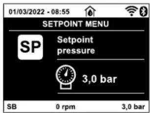
Figure 16: Display of a menu parameter
Pages showing parameters can display: numerical values and units of measure of the current item, values of other parameters linked to the setting of the current item, graphic bar, lists; see Fig.16.
4.5 - Blocking parameter setting by Password
The device has a password-enabled protection system. If a password is set, the parameters of the device will be accessible and visible but it will not be possible to change them. The password management system is in the “technical assistance” menu and is managed by means of the parameter PW.
4.6 - Enabling and disabling the motor
In normal operating conditions, pressing and then releasing both the “A” and “V” keys causes the blocking/release of the motor (self-holding even after switching off). If there is a fault alarm, the operation described above resets the alarm. When the motor is disabled this status is shown by the blinking white LED. This command can be activated from any menu page except RF and PW.
5. MEANING OF THE INDIVIDUAL PARAMETERS

The inverter makes the system work at constant pressure. This regulation is appreciated if the hydraulic plant downstream from the system is suitably sized. Plants made with pipes with too small a section introduce load losses that the equipment cannot compensate; the result is that the pressure is constant on the sensors but not on the utility.

Plants that are excessively deformable can create the onset of oscillations; if this occurs, the problem can be solved by adjusting the control parameters "GP" and "GI" (see par 5.6.3 - GP: Proportional gain coefficient and 5.6.4 - GI: Integral gain coefficient)
5.1 User Menu
From the main menu, pressing the MODE key (or using the selection menu and pressing o v ), gives access to the USER MENU. In the menu the MODE key allows you to scroll through the various menu pages. The values shown are the following.
5.1.1 - Status
Displays the pump status.
5.1.2 - RS: Rotation speed display
Motor rotation speed in rpm.
ENGLISH
5.1.3 - VP: Pressure display
Plant pressure measured in [bar] or [psi] depending on the measuring system used.
5.1.4 - VF: Flow display
Displays the instantaneous flow in [litres/min] or [gal/min] depending on the set measuring system. If the recorded measurement is below the sensitivity threshold of the flow sensor, the measurement value flashes next to the VF identification.
5.1.5 - PO: Absorbed power display
Power absorbed by the electropump in [kW].
If the maximum allowed power is exceeded, the measurement flashes next to the PO identification.
5.1.6 - C1: Phase current display
Motor phase current in [A].
If the maximum allowed current is exceeded, the identification C1 blinks, indicating an imminent tripping of the overload protection.
5.1.7 - SV DV : Supply voltage
Present only in some models.
5.1.8 - SR DV : Supply range
Present only in some models.
Indicates the range of supply voltage found. It may have the values: [110-127] V or [220-240] V. If the range is not determined, it has the value “-”.
5.1.9 - TE: Dissipator temperature display
5.1.10- PKm Ⓚ : Pressure measured at intake
Present only in models with Kiwa function
5.1.11 - Operating hours and number of starts
Indicates on three lines the hours that the device has been powered up, the pump working hours and the number of starts of the motor.
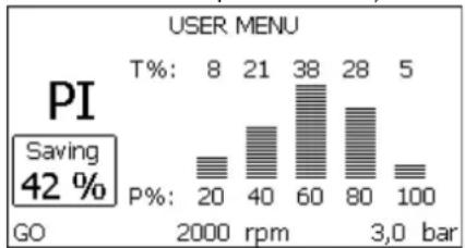
5.1.12 - Pl: Power histogram
A histogram of the power delivered is displayed on 5 vertical bars. The histogram indicates how long the pump has been on at a given power level. On the horizontal axis are the bars at the various power levels; on the vertical axis, the time for which the pump has been on at the specific power level (\% of the time with respect to the total).
bar
USER MENU | RPM | T% | P% | |---|---|---| | 2000 | 8 | 20 | | 40 | 21 | 40 | | 60 | 38 | 60 | | 80 | 28 | 80 | | 100 | 5 | 100 | SPIN Saving 42%Figure 17.1: Power histogram display ^(1)
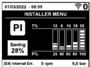
Figure 17.2: Power histogram display (2)
5.1.13 - Output flow meter
The page shows two flow meters. The first shows the total output flow delivered by the machine. The second shows a partial count and can be reset by the user. The partial count can be reset from this page, by holding down the "v" button for 2 sec.
5.1.14 - NT: Display of network configuration (2)
Information on network and serial connectors. The serial connector can be displayed in full by pressing the “^” key.
5.1.15 - VE: Version Display
Information on the hardware version, serial number and mac address of the pump.
5.1.16 - FF: Fault & Warning display (Log)
Chronological display of the faults that have occurred during system operation. Under the symbol FF appear two numbers x/y indicating respectively the ault displayed and the total number of faults present; to the right of these numbers is an indication of the type of fault displayed. The ∧ and ∨ keys scroll through the list of faults: pressing the ∨ key goes back through the log and stops at the oldest fault present, pressing the ∧ key goes forward in the log and stops at the most recent fault. The faults are displayed in chronological order starting from the one that appeared farthest back in time x=1 to the most recent x=y. The maximum number of faults that can be shown is 64; when that number is reached, the log starts to overwrite the oldest ones. This item on the menu displays the list of faults, but does not allow reset. Reset can be carried out only with
ENGLISH
the dedicated control from item RF on the TECHNICAL ASSISTANCE MENU. The fault log cannot be deleted with a manual reset, by switching off the appliance, or by resetting the factory values, unless the procedure described above has been followed.
5.2 - Monitor Menu
From the main menu, by holding down simultaneously for 2 sec the keys "SET" and "v" (minus), or using the selection menu and pressing or , you can access the MONITOR MENU. In this menu, by pressing the MODE key, the following values are displayed in sequence.
5.2.1 - CT: Display contrast
Parameter not available on pumps with firmware version 3.xx. Adjusts the display contrast.
5.2.2 - BK: Display brightness
Adjusts the backlighting of the display on a scale from 0 to 100.
5.2.3 - TK: Backlight switch-on time
Sets the time that the backlight is lit since the last time a key was pressed. Values allowed: 20 sec to 10 min or always on (even if this option is selected, the screen will still go into standby mode after a few hours of inactivity to safeguard the integrity of the device). When the backlight is off, the first time any key is pressed has the sole effect of restoring the backlighting.
5.2.4 - LA: Language
Display in one of the following languages:
- Italian
- Spanish
- Slovak
- Portuguese (2)
- English
- Dutch
- Romanian
- Polish (2)
- French
- Swedish
- Russian
- Chinese (2)
- German
- Turkish
- Thai
- Czech (2)
5.2.5 - TE: Dissipator temperature display
5.3 - Setpoint Menu
From the main menu, hold down simultaneously the "MODE" and "SET" keys until "SP" appears on the display (or use the selection menu pressing ∧ or ∨). The ∧ and ∨ keys allow you respectively to increase and decrease the plant boosting pressure.
Press SET to leave this menu and return to the main menu. The range of adjustment is 1-5.5 bar (14-80 psi).
5.3.1 - SP: Setting the setpoint pressure
Pressure at which the system is pressurised.

The pump restarting pressure is linked not only to the set pressure SP but also to RP. RP expresses the decrease in pressure, with respect to “SP” caused by the pump starting.
For example: SP = 3,0 [bar]; RP = 0,3 [bar];
During normal operation the system is pressurised at 3.0 [bar].
The electropump restarts when the pressure falls belowai 2,7 [bar].

Setting a pressure (SP) that is too high for the pump performance may cause false water lack errors BL; in these cases lower the set pressure.
5.4 - Manual Menu

In manual operation, the sum of the input pressure and the maximum pressure that can be supplied must not be greater than 6 bar.
From the main menu, hold down simultaneously the "SET" and "^" and "v" keys until the manual menu page appears (or use the selection menu pressing ^ or v). Press SET to leave this menu and return to the main menu. Entering the manual menu by pressing the SET ^ v keys puts the machine into forced STOP condition. This function can be used to force the machine to stop. In the main menu, irrespective of the parameter displayed, it is always possible to perform the following controls:
Temporary starting of the electropump.
Pressing the MODE and ^ keys at the same time causes the pump to start at speed RI and this running status remains as long as the two keys are held down. When the pump ON of pump OFF command is given, a communication appears on the display.
Starting the pump
Holding down the MODE v ^ keys simultaneously for 2 sec. causes the pump to start at speed RI. The running status remains until the SET key is pressed. The next time the SET key is pressed the pump leaves the manual menu. When the pump ON of pump OFF command is given, a communication appears on the display. In case of operation in this mode for more than 5' with no flow of liquid, an alarm overheating alarm will
ENGLISH
be triggered, with the error PH shown on the display. Once the PH error condition is no longer present, the alarm will be reset automatically only. The reset time is 15'; if the PH error occurs more than 6 times consecutively, the reset time increases to 1h. Once it has reset further to this error, the pump will remain in stop status until the user restarts it using the "MODE" "v" "^" keys.
5.4.1 - Status
Displays the pump status.
5.4.2 - RI: Speed setting
Sets the motor speed in rpm. Allows you to force the number of revolutions at a predetermined value.
5.4.3 - VP: Pressure display
Plant pressure measured in [bar] or [psi] depending on the measuring system used.
5.4.4 - VF: Flow display
Displays the flow in the chosen unit of measure. The measuring unit may be [l/min] o [gal/min] see par. 5.5.3 - MS: Measuring system. If the recorded measurement is below the sensitivity threshold of the flow sensor, the measurement value flashes next to the VF identification.
5.4.5 - PO: Absorbed power display
Power absorbed by the electropump in [kW].
If the maximum allowed power is exceeded, the measurement flashes next to the PO identification.
5.4.6 - C1: Phase current display
Motor phase current in [A].
If the maximum allowed current is exceeded, the identification C1 blinks, indicating an imminent tripping of the overload protection.
5.4.7 - RS: Rotation speed display
Motor rotation speed in rpm.
5.4.8 - SV DV : Supply voltage
Present only in some models.
Indicates the range of supply voltage found. It may have the values: [110-127] V or [220-240] V. If the range is not determined, it has the value “- -”.
5.4.10 - TE: Dissipator temperature display
5.5 - Installer Menu
From the main menu, hold down simultaneously the "MODE" and "SET" and "v" keys until the first parameter of the installer menu appears on the display (or use the selection menu pressing ∧ or ∨). The menu allows you to view and modify various configuration parameters: the MODE key allows you to scroll through the menu pages, the ∧ and ∨ keys allow you respectively to increase and decrease the value of the parameter concerned. Press SET to leave this menu and return to the main menu.
5.5.1 - RP: Setting the pressure fall to restart
Expresses the fall in pressure with respect to the SP value which causes. Restarting of the pump.
For example if the setpoint pressure is 3.0 [bar] and RP è 0.5 [bar] the pump will restart at 2.5 [bar]. RP can be set from a minimum of 0.1 to a maximum of 1 [bar]. In particular conditions (for example in the case of a setpoint lower than the RP) it may be limited automatically. To assist the user, on the RP setting page the actual restarting pressure also appears highlighted under the RP symbol, see Fig. 18.1-18.2.
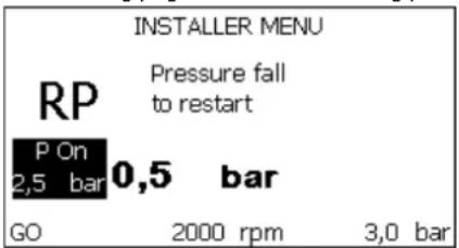
Figure 18.1: Setting the restart pressure (1)
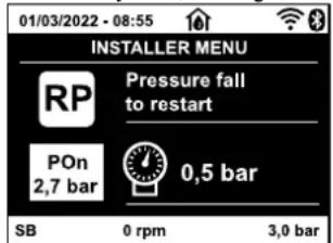
Figure 18.2: Setting the restart pressure (2)
5.5.2 - OD: Type of plant
Possible values 1 and 2 referring to a rigid system and an elastic system.
The device leaves the factory with mode 1 suitable for the majority of systems. In the presence of swings in pressure that cannot be stabilised by adjusting the parameters GI and GP, change to mode 2.
ENGLISH
IMPORTANT: The regulating parameters GP and GI also change in the two configurations. In addition the GP and GI values set in mode 1 are stored in a different memory from the GP and GI values set in mode 2. So, for example, when passing to mode 2, the GB value of mode 1 is replaced by the GB value of mode 2 but it is kept and will reappear again when returning to mode 1. The same value shown on the display has a different weight in one mode or in the other because the control algorithm is different.
5.5.3 - MS: Measuring system
Set the measuring system, choosing between metric and Anglo-American units. The quantities displayed are shown in Table 13.
NOTE: The flow in Anglo-American units (gal/min) is indicated adopting a conversion factor of 1 gal = 4.0 litres, corresponding to the metric gallon.
| Units of measurement displayed | ||
| Quantity | Metric units | Anglo-American units |
| Pressure | Bar | psi |
| Temperature | °C | °F |
| Flow rate | l/min | gal/min |
Table 13 Measuring system
5.5.5 - EK Ⓚ : Setting the low pressure function on suction
Present only in models with Kiwa function.
Sets the low pressure function on suction.
| Value | Function |
| 0 | disabled |
| 1 | enabled with automatic reset |
| 2 | enabled with manual reset |
Table 14
5.5.6 - PK Ⓙ : Low pressure threshold on suction
Present only in models with Kiwa function.
Sets the pressure threshold below which the block is tripped for low pressure on suction.
5.5.7 - T1: Low pressure delay (function detecting low pressure on suction)
Sets the time when the inverter switches off after detecting low pressure on suction (see Setting low pressure detection on suction par. 5.7).
T1 can be set between 0 and 12 s. The factory setting is 2 s.
5.6 - Technical Assistance Menu
Present only in models with Kiwa function.
Advanced settings to be made only by skilled personnel or under the direct control of the service network.
From the main menu, hold down simultaneously the "MODE" and "SET" keys until "SP" appears on the display (or use the selection menu pressing ∧ or ∨). The menu allows you to view and modify various configuration parameters: the MODE key allows you to scroll through the menu pages, the ∧ and ∨ keys allow you respectively to increase and decrease the value of the parameter concerned. Press SET to leave this menu and return to the main menu.
5.6.1 - TB: Water lack blockage time
Setting the reaction time of the water lack blockage allows you to select the time (in seconds) taken by the device to indicate the lack of water. The variation of this parameter may be useful if there is known to be a delay between the moment the motor is switched on and the moment it actually begins to deliver. One example may be a plant where the suction pipe is particularly long and there are some slight leaks. In this case the pipe in question may be discharged and, even though water is not lacking, the electropump will take a certain time to reload, supply the flow and put the plant under pressure.
5.6.2 - T2: Delay in switching off
Sets the delay with which the inverter must switch off after switch-off conditions have been reached: plant under pressure and flow rate lower than the minimum flow. T2 can be set between 2 and 120 s. The factory setting is 10 s.
5.6.3 - GP: Proportional gain coefficient
Generally the proportional term must be increased for systems characterised by elasticity (for example with PVC pipes) and lowered in rigid systems (for example with iron pipes).
To keep the pressure in the system constant, the inverter performs a type PI control on the measured pressure error. Depending on this error the inverter calculates the power to be supplied to the motor. The behaviour of this control depends on the set GP and GI parameters. To cope with the different behaviour of the various types of hydraulic plants where the system can work, the inverter allows the selection of parameters different from those set by the factory. For nearly all plants the factory-set GP and GI parameters are optimal. However, should any problems occur in adjustment, these settings may be varied.
ENGLISH
5.6.4 - Gl: Integral gain coefficient
In the presence of large falls in pressure due to a sudden increase of the flow or a slow response of the system, increase the value of GI. Instead, if there are swings in pressure around the setpoint value, decrease the value of GI.
IMPORTANT: To obtain satisfactory pressure adjustments, you generally have to adjust both GP and GI.
5.6.5 - RM: Maximum speed
Sets a maximum limit on the number of pump revolutions.
5.6.6 - AY: Anti Cycling
As described in paragraph 9, this function is for avoiding frequent switching on and off in the case of leaks in the system. The function can be enabled in 2 different modes, normal and smart. In normal mode the electronic control blocks the motor after N identical start/stop cycles. In smart mode it acts on the parameter RP to reduce the negative effects due to leaks. If set on "Disable", the function does not intervene.
5.6.7 - AE: Enabling the anti-block function
This function is for avoiding mechanical blocks in the case of long inactivity; it acts by periodically rotating the pump.
When the function is enabled, every 23 hours the pump performs an unblocking cycle lasting 1 min.
5.6.8 - AF: Enabling the anti-freeze function
If this function is enabled the pump is automatically rotated when the temperature reaches values close to freezing point, in order to avoid breakages of the pump.
5.7- Setting low pressure detection on suction (typically used in boosting systemsconnected to the water mains)
Present only in models with Kiwa function.
The low pressure detecting function generates the blocking of the system after the time T1 (see 5.5.6 - T1: Low pressure delay).
When this function is active the symbol F4 is shown on the main page.
Tripping of this function causes the pump to cut out; it may be reset automatically or manually. The automatic reset requires that, to leave the error condition F4, the pressure must return to a value 0.3 bar higher than PK for at least 2 sec. To reset the cut-out in manual mode, press and then release the “^” and “v” keys simultaneously.
5.8 - RF: Fault and warning reset
Holding down the ∧ and ∨ keys together for at least 2 seconds deletes the history of faults and warnings. The number of faults present in the log is indicated under the symbol RF (max 64). The log can be viewed from the MONITOR menu on page FF.
5.8.1 - PW: Change password
The device has a password-enabled protection system. If a password is set, the parameters of the device will be accessible and visible but it will not be possible to change them.
When the password (PW) is "0" all the parameters are unlocked and can be edited. When a password is used (value of PW different from 0) all modifications are blocked and "XXXX" is displayed on the page PW.
If the password is set it allows to navigate through all the pages, but at any attempt to edit a parameter a pop-up appears, asking you to type in the password. When the correct password is typed in the parameters are unlocked and can be edited for 10' after the last key is pressed. If you want to cancel the password timer, just go to page PW and hold down ^ and v together for 2". When the correct password is typed in a padlock is shown opening, while if the wrong password is given a flashing padlock appears. After resetting the factory values the password is set back at "0".
Each change of the password takes effect when Mode or Set is pressed and each subsequent change of a parameter implies typing in the new password again (e.g. the installer makes all the settings with the default PW value = 0 and lastly sets the PW so as to be sure that the machine is already protected without any further action).
If the password is lost there are 2 possibilities for editing the parameters of the device:
- Make a note of the values of all the parameters, reset the device with the factory values, see paragraph 7.3. The reset operation cancels all the parameters of the device, including the password.
- Make a note of the number present on the password page, send a mail with this number to your service centre, in a few days you will be sent the password to unlock the device.
6. PROTECTION SYSTEMS
The device is equipped with protection systems to preserve the pump, the motor, the supply line and the inverter. If one or more protections trip, the one with the highest priority is immediately notified on the display. Depending on the type of error the motor may stop, but when normal conditions are restored the error status may be cancelled immediately or only after a certain time, following an automatic reset.
In the case of blockage due to water lack (BL), blockage due to motor overload (OC), blockage due to direct short circuit between the motor phases (SC), you can try to exit the error conditions manually by simultaneously pressing and releasing the and keys. If the error condition remains, you must take steps to eliminate the cause of the fault.
In the event of blocking due to one of the internal errors E18, E19, E20, E21 it is necessary to wait 15 minutes with the machine powered until the blocked status is automatically reset.
ENGLISH
| Alarm in the fault log | |
| Identifying code | Description |
| PD (1) | Irregular switching off |
| HL (1) | Alarm giving advance warning of Hot Fluid Blockage |
| OT | Alarm giving advance warning of Blockage due to overheating of the power amplifiers |
| OBL | Alarm indicating abnormal temperature recorded on the Low Voltage board |
| AYS (2) | “Anti Cycling Smart” function running |
| AE (2) | “Anti Block” function running |
| AF (2) | “Anti Freeze” function running |
| BAT (2) | Low battery |
Table 15: Fault description
| Blockage conditions | |
| Display indication | Description |
| PH | Cutout due to pump overheating |
| BL | Blockage due to water lack |
| BP1 | Blockage due to reading error on the delivery pressure sensor |
| BP2 (K) | Blockage due to reading error on the suction pressure sensor |
| PB (1) | Blockage due to supply voltage outside specifications |
| LP | Block for low DC voltage |
| HP | Block for high DC voltage |
| OT | Blockage due to overheating of the power stages |
| OC (1) | Blockage due to motor overload |
| SC | Blockage due to short circuit between the motor phases |
| ESC | Blockage due to short circuit to earth |
| HL | Hot Fluid Blockage |
| NC | Blockage due to motor disconnected |
| E_i | Blockage due to i-th internal error |
| V_i | Blockage due to i-th internal voltage out of tolerance |
| EY | Block for cyclicality abnormal detected on the system |
Table 16: Indications of blockages
6.1 - Description of blockages
6.1.1 - "BL" Anti Dry-Run (Protection against dry running)
In the case of lack of water the pump is stopped automatically after the time TB. This is indicated by the red “Alarm” led and by the letters “BL” on the display. After having restored the correct flow of water you can try to leave the protective block manually by pressing the “^” and “v” keys simultaneously and then releasing them. If the alarm status remains, or if the user does not intervene by restoring the flow of water and resetting the pump, the automatic restart will try to restart the pump.

If the parameter SP is not correctly set, the protection against water lack may not work correctly.
6.1.2 - Anti-Cycling (Protection against continuous cycles without utility request)
If there are leaks in the delivery section of the plant, the system starts and stops cyclically even if no water is intentionally being drawn: even just a slight leak (a few ml) can cause a fall in pressure which in turn starts the electropump.
The electronic control of the system is able to detect the presence of the leak, based on its recurrence.
The Anti-Cycling function can be excluded or activated in Basic or Smart mode (par 5.6.6).
In Basic mode, once the condition of recurrence is detected the pump stops and remains waiting to be manually reset. This condition is communicated to the user by the lighting of the red "Alarm" led and the appearance of the word "ANTICYCLING" on the display. After the leak has been removed, you can manually force restart by simultaneously pressing and releasing the "^" and "v" keys.
In Smart mode, once the leak condition is detected, the parameter RP is increased to decrease the number of starts over time.
6.1.3 - Anti-Freeze (Protection against freezing of water in the system)
The change of state of water from liquid to solid involves an increase in volume. It is therefore essential to ensure that the system does not remain full of water with temperatures close to freezing point, to avoid breakages of the system. This is the reason why it is recommended to empty any electropump that is going to remain unused during the winter. However, this system has a protection that prevents ice formation inside by activating the electropump when the temperature falls to values close to freezing point. In this way the water inside is heated and freezing prevented.
ENGLISH

The Anti-Freeze protection works only if the system is regularly fed: with the plug disconnected or in the absence of current the protection cannot work.
However, it is advised not to leave the system full during long periods of inactivity: drain the system accurately through the drainage cap and put it away in a sheltered place.
6.1.4 - "BP1" Blockage due to fault of the delivery pressure sensor (system pressurisation)
If the device detects a fault in the delivery pressure sensor the pump remains blocked and the error signal "BP1" is given. This status begins as soon as the problem is detected and ends automatically when correct conditions have been restored.
6.1.5 - "BP2" Blockage due to fault of the suction pressure sensor
If the device detects a fault in the suction pressure sensor the pump remains blocked and the error signal "BP2" is given. This status begins as soon as the problem is detected and ends automatically when correct conditions have been restored.
6.1.6 - "PB" Blockage due to supply voltage outside specifications
This occurs when the allowed line voltage at the supply terminal assumes values outside the specifications. It is reset only automatically when the voltage at the terminal returns within the allowed values.
6.1.7 - "SC" Blockage due to short circuit between the motor phases
The device is provided with protection against the direct short circuit which may occur between the motor phases. When this blockage is indicated you can attempt to restore operation by simultaneously holding down the and keys, but this will not have any effect until 10 seconds have passed since the moment the short circuit occurred.
6.2 - Manual reset of error conditions
In error status, the user can cancel the error by forcing a new attempt, pressing and then releasing the ∧ and ∨ keys.
6.3 - Self-reset of error conditions
For some malfunctions and blockage conditions, the system attempts automatic self-reset.
The auto self-reset procedure concerns in particular:
"BL" Blockage due to water lack
"PB" Blockage due to line voltage outside specifications (1)
"OT" Blockage due to overheating of the power stages
"OC" Blockage due to motor overload (1)
"BP1" Blockage due to fault of the pressure sensor
"BP2" Blockage due to fault of the Kiwa pressure sensor
For example, if the system is blocked due to water lack, the device automatically starts a test procedure to check whether the machine is really left definitively and permanently dry. If during the sequence of operations an attempted reset is successful (for example, the water comes back), the procedure is interrupted and normal operation is resumed.
Table 13 shows the sequences of the operations performed by the device for the different types of blockage..
| Automatic resets of error conditions | ||
| Display indication | Description | Automatic reset sequence |
| BL Blockage due to water lack | - One attempt every 10 minutes for a total of 6 attempts.- One attempt every hour for a total of 24 attempts- One attempt every 24 hours for a total of 30 attempts. | |
| PB(1) | Blockage due to line voltage outside specifications | - It is reset when it returns to a specific voltage. |
| OT | Blockage due to overheating of the power stages | - It is reset when the temperature of the power stages returns within the specifications. |
| OC(1) Blockage due to motor overload | - One attempt every 10 minutes for a total of 6 attempts.- One attempt every hour for a total of 24 attempts.- One attempt every 24 hours for a total of 30 attempts. | |
Table17: Self-reset of blockages
ENGLISH
7. RESET AND FACTORY SETTINGS
7.1 General system reset
To reset the system, hold down the 4 keys simultaneously for 2 sec. This operation is the same as disconnecting the power, waiting for it to close down completely and supplying power again. The reset does not delete the settings saved by the user.
7.2 Factory settings
The device leaves the factory with a series of preset parameters which may be changed according to the user's requirements. Each change of the settings is automatically saved in the memory and, if desired, it is always possible to restore the factory conditions (see Restoring the factory settings par 7.3 - Restoring the factory settings).
7.3 Restoring the factory settings
To restore the factory values, switch off the device, wait until the display has switched off completely, press and hold down the "SET" and "^" keys and turn on the power; release the two keys only when the letters "EE" appear. This restores the factory settings (a message and a rereading on EEPROM of the factory settings permanently saved in the FLASH memory). Once all the parameters have been set, the device returns to normal operation.
NOTE: Once the factory values have been restored it will be necessary to reset all the parameters that characterise the system (gains, setpoint pressure, etc.) as at the first installation.
| Factory settings | ||||
| Identifying code Description | International factory settings | Angloamerican factory settings | Installation Memo | |
| BK | Display brightness | 80% (1) / 50% (2) | 80% (1) / 50% (2) | |
| TK | Backlight lighting T | 2 min | 2 min | |
| LA | Language | English | English | |
| SP | Setpoint pressure | 2,7 bar | 39 psi | |
| RI | Revs per minute in manual mode | 3200 rpm 3200 rpm | ||
| OD | Type of plant | 1 (Rigid) | 1 (Rigid) | |
| RP | Pressure decrease to restart | 0,3 0,3 | ||
| MS | Measuring system | 0 (International) | 0 (International) | |
| EK K | Low pressure function on suction | 1 (Enable) | 1 (Enable) | |
| PK K | Low pressure threshold on suction | 1,0 bar 4 psi | ||
| TB | Blockage time for water lack | 15 s 15 s | ||
| T1 K | Low pr. delay | 2 s 2 s | ||
| T2 | Delay in switching off | 10 s | 10 s | |
| GP | Proportional gain coefficient | 0,5 0,5 | ||
| GI | Integral gain coefficient | 1,2 | 1,2 | |
| RM | Maximum speed | 7000 rpm | 7000 rpm | |
| AE | Anti-blocking function | 1(Enable) | 1(Enable) | |
| AF | Antifreeze | 1(Enable) | 1(Enable) | |
| PW | Change Password | 0 | 0 | |
| AY | Anticycling Function AY | 0 (Disabled) | 0 (Disabled) | |
Table 13: Factory settings
8. APP, DCONNECT CLOUD AND SOFTWARE UPDATE
D CONNECT
The “Smart Solution” APP DConnect is, together with the pump display, the interface for local control of the Esybox Mini pump. Via the DConnect APP you can update the product and configure the main parameters of the device with the convenience of an easy-to-use and always handy APP. The DConnect APP allows you to make the necessary updates (see dedicated section) directly from your smartphone without cumbersome external objects.
Via the APP it is possible to interact locally with the product through the "Direct Connection" menu accessible directly from the main page of the APP.
Menu - Direct connection
The DConnect CLOUD "Smart Solution" allows you to control your systems remotely both through the appropriate internet portal: dconnect.dabpumps.com and through the DConnect APP itself via the appropriate menu "Your installations", accessible directly from the APP main page.
Menu - Your Installations
NOTE 1: The DConnect Cloud remote control service requires registration with the portal and, after a trial period, it requires a subscription. All information is available on the site: www.internetofpumps.com
NOTE 2: This manual refers to DConnect APP menus, colours or descriptions may change.
To get the best out of the product and its interaction with the APP and the DConnect Cloud service, consult also the online documentation and watch the demonstration videos. All the necessary information is available on the site: www.internetofpumps.com or www.dabpumps.com
8.1 - System requirements
- APP requirements: Smartphone
- Android ≥ 8 (API level 23).
- IOS ≥ 12
- Internet access, WiFi and Bluetooth enabled.
- Grant the authorisations proposed from time to time by the smartphone operating system
- Requirements for access from WebAPP: PC
- WEB browser that supports JavaScript (e.g. Microsoft Edge, Firefox, Google Chrome, Safari).
- Internet access.
- Product Network Requirements
- Active and permanent direct Internet connection at the installation site
- Modem/Router WiFi (2,4 Ghz).
- Good quality WiFi signal and power in the area where the product is installed.
NOTE: If the WiFi signal is deteriorated, we suggest using a Wifi Extender. An Internet network test is recommended before configuring the product. The use of DHCP is recommended, although a Static IP can be set.
8.2 - Updating the software
Updates ensure a better use of the services offered by the product.
Before starting to use the product, make sure that it is updated to the latest software version available. During the software update the products involved cannot carry out pumping functions. For this reason a manned update is recommended.
NOTE 1: The update can take up to 5 minutes per product and when it ends the pump will restart.
The software update can be carried out:
- locally: directly from the DConnect APP (recommended)
- remotely if you subscribe to the Cloud DConnect service.
8.3 - Local updates via APP DCONNECT
Be sure to download the latest version of the DConnect DAB APP available from the App Store and Google Play and approve all authorisation requests, policies and terms and conditions that appear on your smartphone screen.

ENGLISH
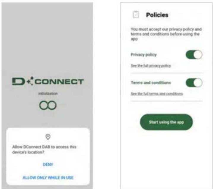
For the first configuration and to update the product, from the APP main page press the button
The App will guide you step-by-step through the local connection procedure and product update.
Menu - Direct connection
Procedure:
- From the product selection menu, choose l'Esybox Mini.
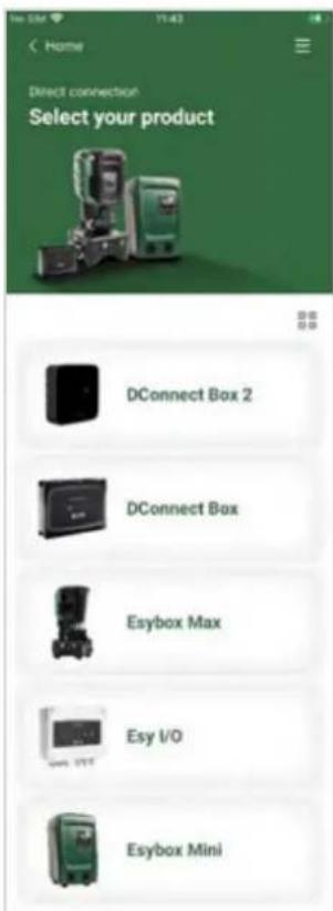
- On the next screen, choose Esybox Mini.
NOTE: To facilitate identification of the product in use and its version, please refer to the information panel in the configuration menu of the APP.
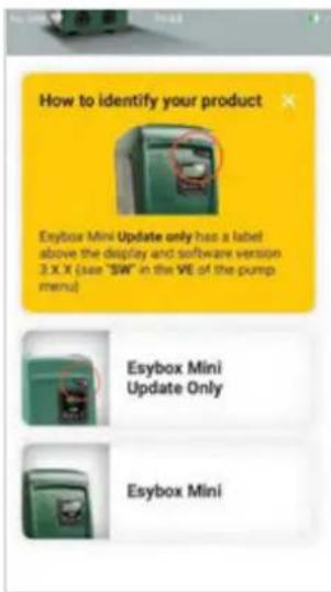
Esybox Mini product type identification
Selecting the product to access (choose Esybox Mini)
ENGLISH
- To complete the direct connection procedure, follow the instructions provided by the APP.
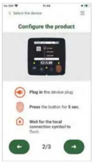
Direct connection instructions
- Once the connection between smartphone and product has been made ("local connection"), the APP will check if a software update is available. If so, a popup will appear on the APP screen.
Press the "Download" button in the popup to download the update software to your smartphone.
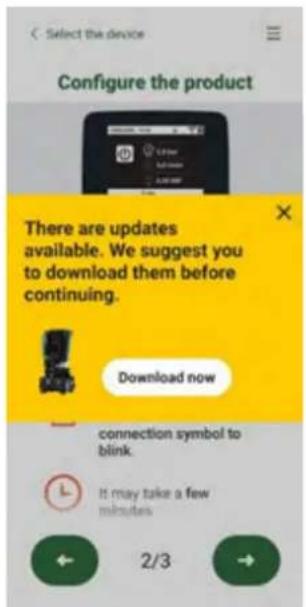
Notification of new available updates
NOTE: This software will remain available in the APP to facilitate any subsequent updates of other Esybox Mini and will remain valid until a new update software is made available and then replaced.
Once you have completed downloading the pump software to your smartphone, access the direct connection menu of the Esybox Mini and press the appropriate button to transfer it to the product:
Product menu with an Update available
Button to start the update
Once the update has started, the pump will show the status on the display, which will end with "Done!" and will restart immediately afterwards. If the update is unsuccessful, the Esybox Mini you were trying to update will restart with the previous software version, so you can repeat the operation.
ENGLISH
9. PARTICULAR INSTALLATIONS
9.1 - Inhibiting self-priming
The product is made and supplied with the capacity of being self-priming. With reference to par. 2.1.2, the system is able to prime and therefore operate in whatever installation configuration chosen: below head or above head. However there are cases in which the self-priming capacity is not necessary, or areas where it is forbidden to use self-priming pumps. During priming the pump obliges part of the water already under pressure to return to the suction part until a pressure value is reached at delivery whereby the system can be considered primed. At this point the recirculating channel closes automatically. This phase is repeated each time the pump is switched on, even already primed, until the same pressure value that closes the recirculating channel is reached (about 1 bar).
When the water arrives at the system intake already under pressure (maximum allowed 2 bar) or when the installation is always below head, it is possible (and mandatory where local regulations require it) to force the closure of the recirculating pipe, losing the self-priming capacity. This obtains the advantage of eliminating the clicking noise of the pipe shutter each time the system is switched on. To force closure of the self-priming pipe, proceed as follows:
- Disconnect the power supply;
- empty the system (unless you decide to inhibit self-priming at the first installation);
- remove the drainage cap on Face E, taking care not to drop the O-Ring (Fig.19);
- with the aid of pliers take the shutter out of its seat. The shutter will be extracted together with the O-Ring and the metal spring with which it is assembled;
- remove the spring from the shutter; insert the shutter in its seat again with the respective O-Ring (side with gasket towards the inside of the pump, stem with cross-shaped fins towards the outside);
- screw on the cap after having positioned the metal spring in side so that it is compressed between the cap itself and the with cross-shaped fins of the shutter stem. When repositioning the cap ensure that the respective O-Ring is always correctly in its seat;
- fill the pump, connect the power supply, start the system.
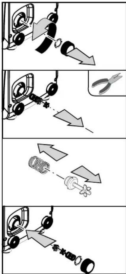
flowchart
graph TD
    A["Wheel with wheels"] --> B["Tool with scissors"]
    B --> C["Spring with spring"]
    C --> D["Clock with clamping mechanism"]
    D --> E["Clamping mechanism"]
Figure 19
9.2 - Wall installation
This product is already set up for installation hanging on the wall with the DAB accessory kit, to be purchased separately. The wall installation appears as in Fig.20.
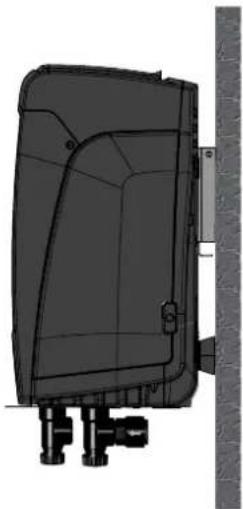
natural_image
3D technical illustration of a mechanical component with mounting brackets and a vertical wall (no text or symbols)Figure 20
10. MAINTENANCE

Disconnect the power supply before starting any work on the system.
ENGLISH
The system requires no routine maintenance operations.
However, below are the instructions for performing the special maintenance operations that may be necessary in particular cases (e.g. emptying the system to put it away during a period of inactivity).
10.1 Accessory tool
With the product, DAB supplies a metal key with a hexagonal section (Fig.21) useful for performing some special maintenance operations on the system, or during installation.
In particular, use the key for the orientation of the interface panel described in par. 2.2.2 or for opening the door of the compartment next to the interface panel. If the key is lost or damaged, the operation can be done using a standard 2mm allen wrench.
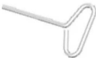
natural_image
Simple line drawing of a paperclip (no text or symbols)Figure 21
10.2 - Emptying the system
If you want to drain the water out of the system, proceed as follows:
- disconnect the power supply;
- turn on the delivery tap closes to the system so as to remove pressure from the system and empty it as much as possible;
- if there is a check valve immediately downstream from the system (always recommended), close it so as not to let out the water that is in the plant between the system and the first turned on tap;
- interrupt the suction pipe in the point closest to the system (it is always recommended to have a check valve immediately upstream from the system) so as not to drain the whole suction system;
- remove the drainage cap Fig.1 face E if vertical configuration; Fig.1 Face C if horizontal configuration) and let out the water inside (about 1.5 litres);
- the water that is trapped in the delivery system downstream from the non-return valve integrated in the system can flow out at the time of disconnecting the system, or on removing the cap of the second delivery (if not used).

Though essentially drained, the system is unable to expel all the water that it contains. During handling of the system after emptying it, some small amounts of water may probably leak out from the system.
10.3 - Non-return valve
The system has an integrated non-return valve which is necessary for correct operation. The presence of solid bodies or sand in the water could cause malfunctioning of the valve and therefore of the system. Although it is recommended to use fresh water and eventually fit filters on input, if you notice abnormal operation of the non-return valve it can be extracted from the system and cleaned and/or replaced by proceeding as follows:
- remove the access door to the special maintenance compartment (Fig.1 Face F) disengaging the 2 fixing screws with the accessory tool. It is advisable not to remove the screws completely, so that you can used them to extract the door. Take care not to drop the screws inside the system once you have removed the door (Fig.22);
- using a screwdriver, remove the 1"1/4 cap so as to access the non-return valve (Fig.22);
- using pliers, extract the cartridge of the non-return valve without rotating it, gripping it by the jumper provided for the purpose (Fig.22): the operation may require a certain effort;
- clean the valve under running water, ensure that it is not damaged and replace it if necessary;
- put the complete cartridge back in its seat: the operation requires the force necessary to compress the 2 O-Rings (Fig.22);
- Screw on the 1"1/4 cap until it is snug: if the cartridge has not been pushed correctly in place, screwing on the cap will complete its positioning (Fig.22);
- reposition the door and tighten the 2 screws (Fig.22).
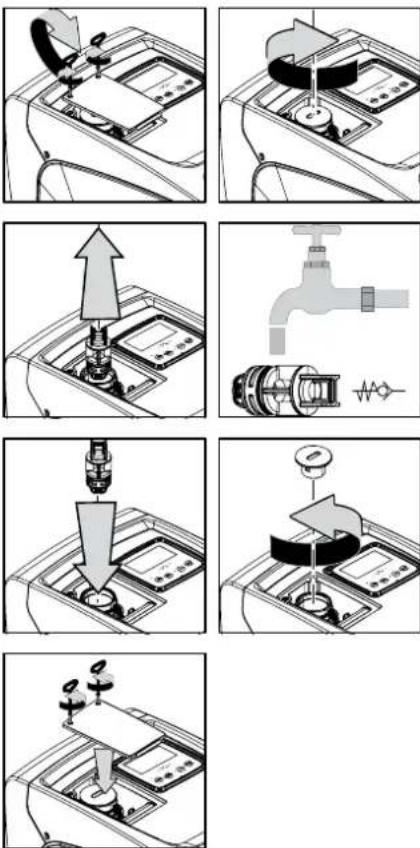
Figure 22

Should one or more O-rings be lost or damaged during maintenance operations on the non-return valve, they must be replaced. Otherwise the system might not work correctly.
ENGLISH
10.4 - Motor shaft
The electronic control of the system ensures smooth starts so as to avoid excessive stress on the mechanical parts and thus prolong the life of the product. In exceptional cases this characteristic could cause problems in starting the pump: after a period of inactivity, perhaps with the system drained, the salts dissolved in the water could have settled and formed calcification between the moving part (motor shaft) and the fixed part of the pump, thus increasing the resistance on starting. In this case it may be sufficient to help the motor shaft by hand to detach itself from the calcifications. In this system the operation is possible because access to the motor shaft from outside is guaranteed and a groove is provided at the end of the shaft. Proceed as follows:
- remove the cover of the technical compartment (Fig. 1 Face A);
- lift the rubber cover of the motor shaft access cap (Fig. 23);
- using a 10mm hexagonal key, remove the motor shaft access cap (Fig. 23);
- insert a straight tip screwdriver in the groove on the motor shaft and manoeuvre, turning in 2 directions (Fig. 23);
- if it is turning freely the system can be started, after having replaced the cap and cover that have been removed;
- if rotation is blocked and it cannot be removed by hand, call the assistance service.
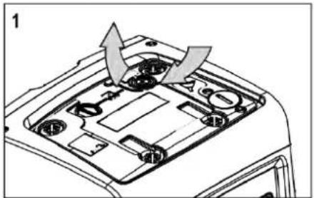
natural_image
Diagram of a car's front engine compartment showing internal components and airflow direction (no text or labels)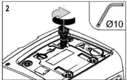
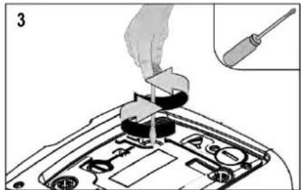
natural_image
Diagram of a car headstock with a hand inserting a tool into the engine compartment, showing internal components and a close-up of the screwdriver (no text or symbols present)Figure 23
10.5 - Expansion Vessel
See paragraph 1.2 for the operations to check and adjust the air pressure in the expansion vessel and to replace it if it is broken.
To access the valve of the expansion vessel, proceed as follows:
- remove the access door to the special maintenance compartment (Fig.1 Face F) disengaging the 2 fixing screws with the accessory tool. It is advisable not to remove the screws completely, so that you can used them to extract the door. Take care not to drop the screws inside the system once you have removed the door (Fig. 24);
- slip the rubber cap off the valve or the expansion vessel (Fig. 24);
- regulate the valve as indicated in paragraph 1.2 (Fig. 24);
- reposition the rubber cap (Fig. 24);
- reposition the door and tighten the 2 screws (Fig. 24).
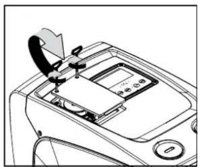
natural_image
Diagram of a car air intake manifold showing valve and control panel (no text or symbols)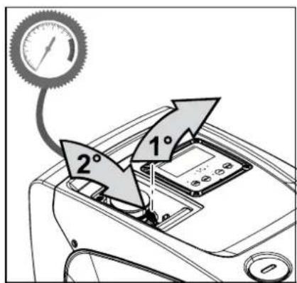
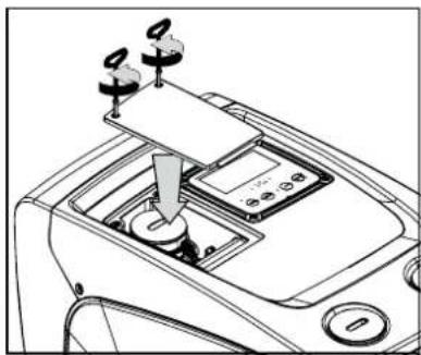
natural_image
Line drawing of a car gear shift lever with control panel and three-mounted sensors (no text or symbols)Figure 24
11. TROUBLESHOOTING

Before starting to look for faults it is necessary to disconnect the power supply to the pump (take the plug out of the socket).
| Fault | LED | Probable Causes | Remedies |
| The pump does not start. | Red: offWhite: offBlue: off | No electric power. | Check whether there is voltage in the socket and insert the plug again. |
| The pump does not start. | Red: onWhite: onBlue: off | Shaft blocked. | See paragraph 9.4 (motor shaft maintenance). |
ENGLISH
| The pump does not start. | Red: offWhite: onBlue: off | Utility at a level higher than the system restarting pressure level (par. 3.2). | Increase the system restarting pressure level by increasing SP or decreasing RP. |
| The pump does not stop. | Red: offWhite: onBlue: off | 1. Leak in the system.2. Impeller or hydraulic part clogged.3. Air getting into the suction pipe.4. Faulty flow sensor | 1. Check the system, find and eliminate the leak.2. Dismantle the system and remove the obstructions (assistance service).3. Check the suction pipe, find and eliminate the cause of air getting in.4. Contact the assistance centre. |
| Insufficient delivery | Red: offWhite: onBlue: off | 1. Suction depth too high.2. Suction pipe clogged or diameter insufficient.3. Impeller or hydraulic part clogged. | 1. As the suction depth increases the hydraulic performance of the product decreases. Check whether the suction depth can be reduced. Use a suction pipe with a larger diameter (but never smaller than 1").2. Check the suction pipe, find the cause of choking (obstruction, dry bend, counterslope, ...) and remove it.3. Dismantle the system and remove the obstructions (assistance service). |
| The pump starts without utility request. | Red: offWhite: onBlue: off | 1. Leak in the system.2. Faulty non-return valve. | 1. Check the system, find and eliminate the leak.2. Service the non-return valve as described in par. 9.3. |
| The water pressure when turning on the utility is not immediate. | Red: offWhite: onBlue: off | Expansion vessel empty (insufficient air pressure) or has broken diaphragm. | Check the air pressure in the expansion vessel. If water comes out when checking, the vessel is broken: assistance service. Otherwise restore the air pressure according to the equation par. 1.2. |
| When the utility is turned on the flow falls to zero before the pump starts | Red: offWhite: onBlue: off | Air pressure in the expansion vessel higher than the system starting pressure. | TCalibrate the expansion vessel pressure or configure the parameters SP and/or RP so as to satisfy the equation par.1.2. |
| The display shows BL | Red: onWhite: onBlue: off | 1. No water.2. Pump not primed.3. Setpoint not reachable with the set RM value | 1-2. Prime the pump and check whether there is air in the pipe. Check whether the suction or any filters are blocked.3. Set a RM value that allows the setpoint to be reached. |
| The display shows BP1 | Red: onWhite: onBlue: off | Faulty pressure sensor. Contact the assistance centre. | |
| The display shows BP2 | Red: onWhite: onBlue: off | Faulty pressure sensor. Contact the assistance centre. | |
| The display shows OC | Red: onWhite: onBlue: off | 1. Excessive absorption.2. Pump blocked. | 1. Fluid too dense. Do not use the pump for fluids other than water.2. Contact the assistance centre. |
| The display shows PB | Red: onWhite: onBlue: off | 1. Supply voltage too low.2. Excessive drop in voltage on the line. | 1. Check the presence of the correct supply voltage.2. Check the section of the power supply cables. |
12. UPDATING THE FIRMWARE
Firmware version 3.xx can only be updated via App, for other versions the update can be done via D-connect Box through wireless communication. For further information on the latter type of update please refer to the D-Connect Box manual.
13. DISPOSAL
This product or its parts must be disposed of in an environment-friendly manner and in compliance with the local regulations concerning the environment; use public or private local waste collection systems.
14. GUARANTEE
Any use of faulty material or manufacturing defects of the appliance will be eliminated during the guarantee period contemplated by the law in force in the country where the product is purchased, by repair or replacement, as we decide.
The guarantee covers all substantial defects that can be assigned to manufacturing faults or to the material used if the product has been used correctly, in accordance with the instructions.
The guarantee is void in the following cases:
- attempts to repair the appliance,
• technical alterations to the appliance,
• use of non original spare parts, - tampering,
- inappropriate use, for example industrial use.
Excluded from the guarantee:
- parts subject to rapid wear.
When making a request under guarantee, apply to an authorised technical assistance service, presenting proof of purchase of the product.
FRANÇAIS
SOMMAIRE
1. GÉNÉRALITÉS 68
Image 3
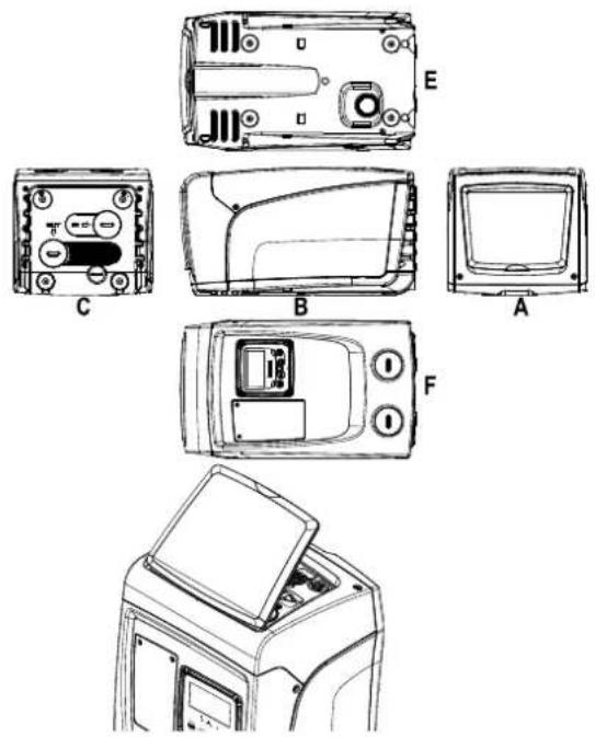
natural_image
Line drawing of a portable electronic device with control panel and buttons (no text or symbols)Image 4
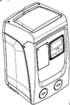
natural_image
Line drawing of a portable electronic device with control panel and buttons (no text or symbols)Image 5
natural_image
Line drawing of a portable air conditioner unit with control panel and buttons (no text or symbols)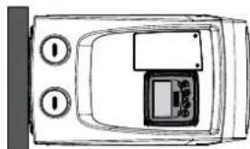
natural_image
Top-down schematic of a device casing with control buttons and display panel (no text or symbols)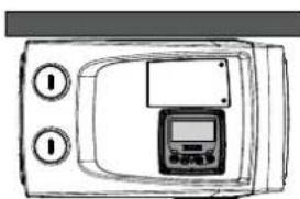
natural_image
Line drawing of a device casing with control panel and buttons (no text or symbols)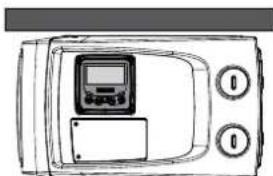
natural_image
Top-down line drawing of a portable electronic device with control panel and two circular buttons (no text or symbols)Image 9
natural_image
Four-panel technical diagram showing mechanical assembly steps with no visible text or symbolsImage 11.1: Pop-up amorçage (1)
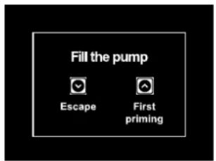
Image 11.2: Pop-up amorçage (2)
Image 12
5.6 - Menu Assistance technique
Menu - Vos installations
9.2 - Installation murale
natural_image
Technical line drawing of a mechanical component with mounting bracket and side panel (no text or symbols)Image 20
10. ENTRETIEN
natural_image
Simple line drawing of a paperclip (no text or symbols)Image 21
natural_image
Diagram of a car's front engine compartment showing internal components and airflow direction (no text or labels)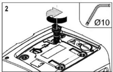
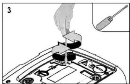
natural_image
Diagram showing a hand inserting a component into a car's head panel with a screwdriver inserted (no text or symbols)Image 23
FRANÇAIS
natural_image
Line drawing of a car interior showing a hand holding a device with control buttons and a display panel (no text or symbols)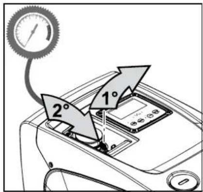
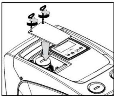
natural_image
Line drawing of a car interior showing a hand presser and control panel (no text or symbols)Image 24
11. RÉSOLUTION DES PROBLÈMES

Severalls Business Park
Colchester
Essex
C04 9WN - UK
salesuk@dwtgroup.com
Tel. +44 0333 777 5010
DAB PUMPS BV
'tHofveld 6 C1
info.belgium@dwtgroup.com
Tel. +32 2 4668353
DAB PUMPS INC.
3226 Benchmark Drive
Ladson, SC 29456 - USA
info.usa@dwtgroup.com
Tel. 1-843-797-5002
Fax 1-843-797-3366
000 DAB PUMPS
Novgorodskaya str. 1, block G
office 308, 127247, Moscow - Russia
info.russia@dwtgroup.com
Tel. +7 495 122 0035
Fax +7 495 122 0036
DAB PUMPS POLAND SP. z.o.o.
No.40 Kaituo Road, Qingdao Economic &
Technological Development Zone
Qingdao City, Shandong Province - China
PC: 266500
sales.cn@dwtgroup.com
Tel. +86 400 186 8280
Fax +86 53286812210
DAB PUMPS IBERICA S.L.
Calle Verano 18-20-22
28850 - Torrejón de Ardoz - Madrid
Spain
Info.spain@dwtgroup.com
Tel. +34 91 6569545
Fax: + 34 91 6569676
DAB PUMPS B.V.
Twenty One industrial Estate,
16 Purlin Street, Unit B, Warehouse 4
Olifantsfontein - 1666 - South Africa
info.sa@dwtgroup.com
Tel. +27 12 361 3997
DAB PUMPS GmbH
Am Nordpark 3
41069 Mönchengladbach, Germany
info.germany@dwtgroup.com
Tel. +49 2161 47 388 0
Fax +49 2161 47 388 36
DAB PUMPS HUNGARY KFT.
H-8800
Nagykanizsa, Buda Ernő u.5
Hungary
Tel. +36 93501700
426 South Gippsland Hwy,
Dandenong South VIC 3175 – Australia
info.oceania@dwtgroup.com
Tel. +61 1300 373 677

WATER•TECHNOLOGY
DAB PUMPS S.p.A.
Via M. Polo, 14 - 35035 Mestrino (PD) - Italy
Tel. +39 049 5125000 - Fax +39 049 5125950
www.dabpumps.com


- INSTALLATION....39
- COMMISSIONING 42
- THE KEYPAD AND THE DISPLAY 44
- MEANING OF THE INDIVIDUAL PARAMETERS ....49
- ENGLISH
- KEY
- SITUATION OF GENERAL DANGER.
- SITUATION OF ELECTRIC SHOCK HAZARD.
- WARNINGS
- RESPONSIBILITY
- GENERAL
- Applications
- Description of the Integrated Inverter
- Integrated Expansion Vessel
- INSTALLATION
- - Vertical Configuration
- Hydraulic connections
- Loading Operation - Installation above head and below head
- - Horizontal Configuration
- Hydraulic connections
- Orientation of the Interface Panel
- Loading Operation - Installation above head and below head
- COMMISSIONING
- Electrical Connections
- Configuration of the Integrated Inverter
- - Priming
- Operation
- THE KEYPAD AND THE DISPLAY
- Table 5
- Warning leds
- Menus
- Access to the menus
- Direct Access with a Combination of Keys
- - Access by name with a drop-down menu
- - Structure of the menu pages. (FIRMWARE VERSION ≤ 4.x.x)
- - Structure of the menu pages. (FIRMWARE VERSION ≥ 4.x.x)
- - Blocking parameter setting by Password
- - Enabling and disabling the motor
- MEANING OF THE INDIVIDUAL PARAMETERS
- User Menu
- - Status
- - RS: Rotation speed display
- - VP: Pressure display
- - VF: Flow display
- - PO: Absorbed power display
- - C1: Phase current display
- - SV DV : Supply voltage
- - SR DV : Supply range
- - TE: Dissipator temperature display
- 5.1.10- PKm Ⓚ : Pressure measured at intake
- - Operating hours and number of starts
- - Pl: Power histogram
- - Output flow meter
- - NT: Display of network configuration (2)
- - VE: Version Display
- - FF: Fault & Warning display (Log)
- - Monitor Menu
- - CT: Display contrast
- - BK: Display brightness
- - TK: Backlight switch-on time
- - LA: Language
- - TE: Dissipator temperature display
- - Setpoint Menu
- - SP: Setting the setpoint pressure
- - Manual Menu
- - Status
- - RI: Speed setting
- - VP: Pressure display
- - VF: Flow display
- - PO: Absorbed power display
- - C1: Phase current display
- - RS: Rotation speed display
- - SV DV : Supply voltage
- - TE: Dissipator temperature display
- - Installer Menu
- - RP: Setting the pressure fall to restart
- - OD: Type of plant
- - MS: Measuring system
- - EK Ⓚ : Setting the low pressure function on suction
- - PK Ⓙ : Low pressure threshold on suction
- - T1: Low pressure delay (function detecting low pressure on suction)
- - Technical Assistance Menu
- - TB: Water lack blockage time
- - T2: Delay in switching off
- - GP: Proportional gain coefficient
- - Gl: Integral gain coefficient
- - RM: Maximum speed
- - AY: Anti Cycling
- - AE: Enabling the anti-block function
- - AF: Enabling the anti-freeze function
- 5.7- Setting low pressure detection on suction (typically used in boosting systemsconnected to the water mains)
- - RF: Fault and warning reset
- - PW: Change password
- PROTECTION SYSTEMS
- - Description of blockages
- - "BL" Anti Dry-Run (Protection against dry running)
- - Anti-Cycling (Protection against continuous cycles without utility request)
- - Anti-Freeze (Protection against freezing of water in the system)
- - "BP1" Blockage due to fault of the delivery pressure sensor (system pressurisation)
- - "BP2" Blockage due to fault of the suction pressure sensor
- - "PB" Blockage due to supply voltage outside specifications
- - "SC" Blockage due to short circuit between the motor phases
- - Manual reset of error conditions
- - Self-reset of error conditions
- RESET AND FACTORY SETTINGS
- General system reset
- Factory settings
- Restoring the factory settings
- APP, DCONNECT CLOUD AND SOFTWARE UPDATE
- D CONNECT
- - System requirements
- - Updating the software
- - Local updates via APP DCONNECT
- Procedure:
- PARTICULAR INSTALLATIONS
- - Inhibiting self-priming
- - Wall installation
- MAINTENANCE
- Accessory tool
- - Emptying the system
- - Non-return valve
- - Motor shaft
- - Expansion Vessel
- TROUBLESHOOTING
- UPDATING THE FIRMWARE
- DISPOSAL
- GUARANTEE
- FRANÇAIS
- SOMMAIRE
- GÉNÉRALITÉS 68
- Image 9
- - Menu Assistance technique
- - Installation murale
- ENTRETIEN
- RÉSOLUTION DES PROBLÈMES
- DAB PUMPS BV
- DAB PUMPS INC.
- DAB PUMPS
- DAB PUMPS POLAND SP. z.o.o.
- DAB PUMPS IBERICA S.L.
- DAB PUMPS B.V.
- DAB PUMPS GmbH
- DAB PUMPS HUNGARY KFT.
- DAB PUMPS S.p.A.
Brand : DAB
Model : Esybox Mini 3
Category : Water pump