
POWX075751DB - Saw PowerPlus - Free user manual and instructions
Find the device manual for free POWX075751DB PowerPlus in PDF.

| Product type | Telescopic double bevel miter saw |
| Brand | PowerPlus |
| Model | POWX075751DB |
| Rated power | 2000 W (S6 40%) |
| Supply voltage | 220-240 V ~ 50 Hz |
| No-load speed | 3800 min⁻¹ |
| Blade diameter | 305 mm |
| Blade bore | 30 mm |
| Blade thickness | 2.8 mm |
| Number of blade teeth | 40 |
| Cutting capacity at 90° (H x W) | 105 x 330 mm |
| Cutting capacity at 45° head tilt | 105 x 230 mm |
| Cutting capacity at 45° table | 60 x 330 mm |
| Miter angle (table) | 0° to 45° left/right |
| Bevel angle (head) | 0° to 45° left/right |
| Laser guide | Yes, class 2 |
| Dust collection system | Integrated sawdust bag |
| Protection class | II (double insulation) |
| Included accessories | Hex key, clamp, 2 side support bars, dust bag |
| Recommended maintenance | Clean with soft cloth, no solvents |
| Safety | Lock-off switch, blade guard, spindle lock |
| Warranty | 36 months |
Frequently Asked Questions - POWX075751DB PowerPlus
User questions about POWX075751DB PowerPlus
0 question about this device. Answer the ones you know or ask your own.
Ask a new question about this device
Download the instructions for your Saw in PDF format for free! Find your manual POWX075751DB - PowerPlus and take your electronic device back in hand. On this page are published all the documents necessary for the use of your device. POWX075751DB by PowerPlus.
USER MANUAL POWX075751DB PowerPlus
natural_image
Yellow and black cutting machine with yellow blade and gray base, mounted on a metal workbench (no visible text or symbols)
NL NEDERLANDS VERTAALDE VERSIE VAN DE ORIGINELE HANDLEIDING
FR FRANÇAIS TRADUCTION DU MODE D'EMPLOI D'ORIGINE
EN ENGLISH ORIGINAL INSTRUCTION MANUAL
FIG. A
natural_image
Close-up of a person's hand holding a small electronic device with labeled ports (no readable text or symbols)
1 TOEPASSING 3
2 OMSCHRIJVING (FIG. A & B)....3
3 INHOUD VAN DE VERPAKKING....3
4 TOELICHTING VAN DE SYMBOLEN 4
5 ALGEMENE VEILIGHEIDSVOORSCHRIFTEN ....4
5.1 Werkplaats....4
5.2 Elektrische veiligheid ....4
15 PROBLEEMOPLOSSING
28/10/2021, Lier - Belgium
1 APPLICATION....3
2 DESCRIPTION (FIG. A & B) 3
3 LISTE DES PIÈCES CONTENUES DANS L'EMBALLAGE ...... 3
4 PICTOGRAMMES 4
5 CONSIGNES DE SÉCURITÉ GÉNÉRALES......4
28/10/2021, Lier - Belgium
1 APPLICATION....3
2 DESCRIPTION (FIG A & B) 3
3 PACKAGE CONTENT LIST....3
4 SYMBOLS 4
5 GENERAL POWER TOOL SAFETY WARNINGS ....4
5.1 Working area....4
5.2 Electrical safety....4
5.3 Personal safety 5
5.4 Power tools use and care....5
5.5 Service....5
6 ADDITIONAL SAFETY INSTRUCTIONS ....5
7 ADDITIONAL SAFETY INSTRUCTIONS FOR LASERS......7
8 ASSEMBLY 7
8.1 Assembling the saw (Fig. 1 - 6)....7
9 OPERATING INSTRUCTIONS 8
9.1 Precision adjustment of the stop for mitre cut 45° (Fig. 1, 3, 5, 15)....8
9.2 Precision adjustment of the stop for crosscut 90° (Fig. 3, 5, 14)....8
9.3 Making a straight cross cut at 90^ (machine head bevel at 0^ and turntable 0^ ) (Fig. 1, 2, 6, 7).....8
9.4 Straight cross cut 90° with mitre angle (machine head bevel at 0° and turntable between 0°-45°) (Fig. 1, 6, 7)....9
9.5 Bevel cut 0°-45° (turntable at 0°) (Fig. 1, 2, 6, 8)....9
9.6 Bevel cut 0°-45° and mitre cut 0°-45° (machine head at 0°-45° and turntable 0°-45°) (Fig. 1, 2, 6, 9) ..... 10
9.7 Limiting the cutting depth (Fig. 3)....10
9.8 Sawdust bag (Fig. 2)....10
9.9 Changing the saw blade (Fig. 10,11,12 and 13)....10
10 TECHNICAL DATA....11
11 CUTTING CAPACITY....11
12 NOISE....11
13 STORAGE 11
POWERPLUS® HIGH QUALITY TOOLS
POWX075751DB EN
14 TROUBLE SHOOTING 12
15 WARRANTY....12
16 ENVIRONMENT 13
17 DECLARATION OF CONFORMITY 13
DOUBLE BEVEL SLIDING MITRE SAW 2000W-305MM POWX075751DB
1 APPLICATION
This power tool is intended as a stationary machine for making straight and cross cuts in wood.
You can saw hard and soft wood as well as chip and fibre boards.
Only adults may use this tool.
Not suitable for professional use/

WARNING! For your own safety, read this manual and the general safety instructions carefully before using the appliance. Your power tool should only be given to other users together with these instructions.
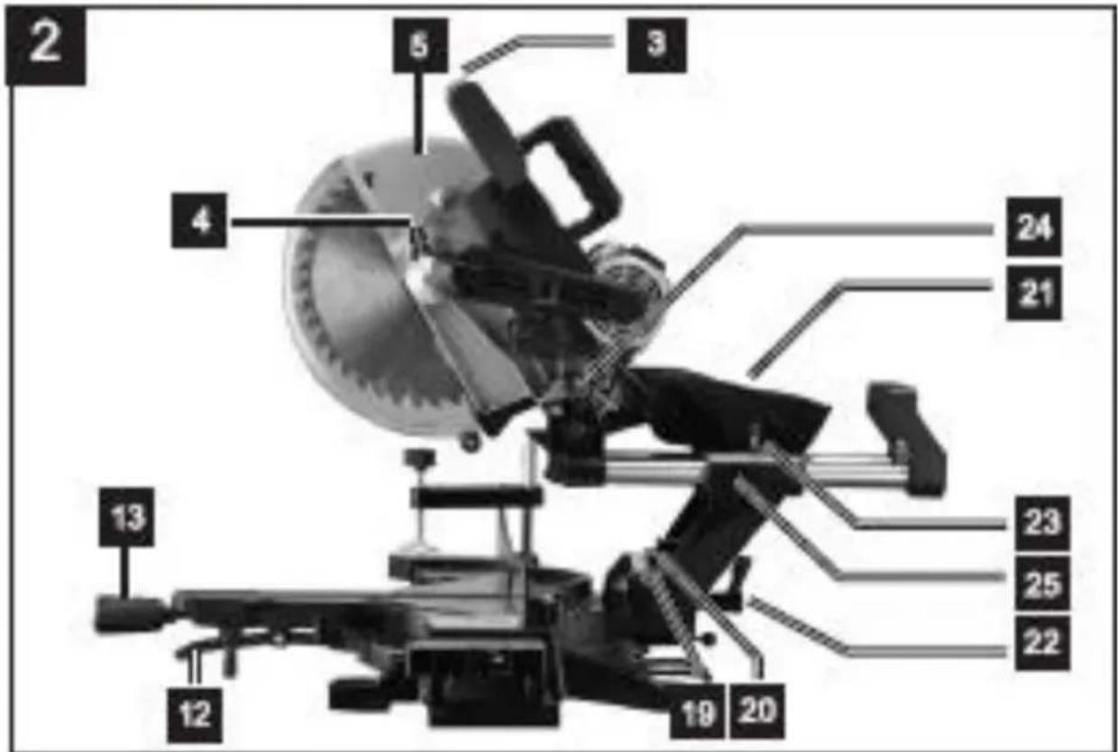
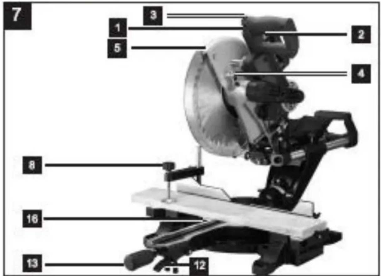
2 DESCRIPTION (FIG A & B)
- Handle
- ON/OFF switch
- Lock switch
- Saw shaft lock
- Machine head
- Movable blade guard
- Saw blade
- Clamping device
- Workpiece support
- Locking screw for workpiece support
- Table insert
- Indexed position lever
- Turntable handle
- Pointer
- Scale
- Turntable
- Fixed saw table
-
Back fence
-
Scale
- Pointer
- Sawdust bag
- Lock screw 22 a. Safety bolt
- Sliding bar lock screw
- Locking pin
- Slide bar
- Screw for cutting depth limiter
- Stop for cutting depth limiter
- Back fence
- Lock screw for back fence
- Adjustment screw (90°)
- Adjustment screw (45°)
- Flange screw
- Outer flange
- Inner flange
3 PACKAGE CONTENT LIST
■ Remove all packaging materials.
■ Remove remaining packaging and packing inserts (if included).
- Check that the package contents are complete.
- Check the appliance, the power cord, the power plug and all accessories for transportation damage.
- Keep the packaging materials as far as possible until the end of the warranty period. Then take it to your local waste disposal system.

WARNING! Packaging materials are not toys! Children must not play with plastic bags! There is a danger of suffocation!
In this packaging, you can find:
1 mitre saw
1 hex spanner,
1 clamp
1 manual
2 x Side support bar
1 dust bag
1 x Blade: ∅ 305 x 30 x 2,8mm (40T)

If any parts are missing or damaged, please contact your dealer.
4 SYMBOLS
The following symbols are used in this manual and/or on the machine:
 | Denotes risk of personal injury or damage to the tool. |  | Wear eye protection . |
 | Read manual before use. |  | In accordance with essential requirements of the European directive(s) |
 | Wear gloves. |  | Class II - The machine is double insulated; Earthing wire is therefore not necessary. |
5 GENERAL POWER TOOL SAFETY WARNINGS

Read all safety warnings and instructions. Failure to heed warnings and follow instructions may result in electric shock, fire and/or serious injury. Keep safety warnings and instructions for future reference. The term "power tool" in the safety warnings refers to your mains-operated (corded) power tool or battery-operated (cordless) power tool.
5.1 Working area
- Keep working area clean and well lit. Untidy and dark areas can lead to accidents.
- Do not operate power tools in potentially explosive surroundings, for example, in the presence of inflammable liquids, gases or dust. Power tools create sparks which may ignite the dust or fumes.
- Keep children and bystanders at a distance when operating a power tool. Distractions can cause you to lose control of it.
5.2 Electrical safety

Always check that the power supply corresponds to the voltage on the rating plate.
- Power tool plugs must match the outlet. Never modify the plug in any way. Do not use adapter plugs with earthed power tools. Unmodified plugs and matching outlets will reduce the risk of an electric shock.
- Do not expose power tools to rain or wet conditions. If water gets inside a power tool, it will increase the risk of an electric shock.
- Do not damage the cord. Never use the cord for carrying, pulling or unplugging the power tool. Keep the cord away from heat, oil, sharp edges or moving parts. Damaged or entangled cords increase the risk of an electric shock.
- When operating a power tool outdoors, use an extension cable suitable for outdoor use. Using a cord suitable for outdoor use reduces the risk of an electric shock.
- If operating a power tool in a damp location is unavoidable, use a power supply protected by a residual current device (RCD). Using an RCD reduces the risk of an electric shock.
5.3 Personal safety
- Stay alert, watch what you are doing and use common sense when operating a power tool. Do not use a power tool when you are tired or under the influence of drugs, alcohol or medication. A moment of inattention when operating a power tool may result in serious personal injury.
- Use safety equipment. Always wear eye protection. Using safety equipment such as a dust mask, non-skid safety shoes, a hard hat, or hearing protection whenever it is needed will reduce the risk of personal injury.
- Avoid accidental starts. Ensure the switch is in the off position before inserting the plug. Carrying power tools with your finger on the switch or plugging in power tools when the switch is in the on position makes accidents more likely.
- Remove any adjusting keys or spanners before turning on the power tool. A spanner or key left attached to a rotating part of the power tool may result in personal injury.
- Do not reach out too far. Keep your feet firmly on the ground at all times. This will enable you retain control over the power tool in unexpected situations.
- Dress properly. Do not wear loose clothing or jewellery. Keep your hair, clothing and gloves away from the power tool. Loose clothes, jewellery or long hair can become entangled in the moving parts.
- If there are devices for connecting dust extraction and collection facilities, please ensure that they are attached and used correctly. Using such devices can reduce dust-related hazards.
5.4 Power tools use and care
- Do not expect the power tool to do more than it can. Use the correct power tool for what you want to do. A power tool will achieve better results and be safer if used in the context for which it was designed.
- Do not use the power tool if the switch cannot turn it on and off. A power tool with a broken switch is dangerous and must be repaired.
- Disconnect the plug from the power source before making adjustments, changing accessories, or storing power tools. Such preventive safety measures reduce the risk of starting the power tool accidentally.
- Store power tools, when not in use, out of the reach of children and do not allow people who are not familiar with the power tool or these instructions to operate it. Power tools are potentially dangerous in the hands of untrained users.
- Maintain power tools. Check for misalignment or jammed moving parts, breakages or any other feature that might affect the operation of the power tool. If it is damaged, the power tool must be repaired. Many accidents are caused by using poorly maintained power tools.
- Keep cutting tools sharp and clean. Properly maintained cutting tools with sharp cutting edges are less likely to jam and are easier to control.
- Use the power tool, accessories and cutting tools, etc., in accordance with these instructions and in the manner intended for the particular type of power tool, taking into account the working conditions and the work which needs to be done. Using a power tool in ways for which it was not intended can lead to potentially hazardous situations.
5.5 Service
Your power tool should be serviced by a qualified specialist using only standard spare parts.
This will ensure that it meets the required safety standards.
6 ADDITIONAL SAFETY INSTRUCTIONS
■ Always wear eye protectors.
- Never use the equipment in the presence of flammable liquids or gases.
- NEVER use the equipment when a cutting disc (and not a saw disc) has been attached.
- Before each use, check the saw blade for small cracks or damages. Replace a cracked or damaged blade immediately.
- Only use saw blades that are recommended by the manufacturer and that fulfil the EN847-1 standard.
- Always use the accessories that are recommended by this manual.
- Select the correct saw blade for the material must be sawn.
- To reduce the generation of noise, always make sure that the blade is sharp and clean.
- Only use correctly sharpened saw blades. Never exceed the maximum speed that is indicated on the saw blade.
■ Before installing the saw blade, clean the axle, the flanges (especially the assembly surfaces) and the hexagonal nut. Incorrect mounting can lead to vibrations/knocking or slipping of the saw blade.
- Prevent that the saw comes into contact with metals, such as nails and screws. Search for and remove all nails, screws and other foreign materials from the workpiece, before you start to work.
- Remove spanners, cut off pieces and the other items from the saw table, before turning on the switch.
- NEVER wear gloves while working; the wearing of gloves is only recommended while cutting tools are being replaced.
■ Make sure that your hands stay clear of the cutting line of the saw blade.
- NEVER stand in the cutting line of the saw blade and NEVER let anyone else stand in that position.
- Let the saw run for a few moments before inserting a workpiece. Listen for vibrations or knocking of the saw blade, which can indicate improper mounting or balancing of the blade.
- The equipment may not be used for making grooves or recesses.
- Replace the table insert when it is worn out.
- NEVER make any adjustments on the machine while it is turning. Remove the plug from the socket before making any adjustments.
- If necessary, use a push block. A push block MUST be used for longitudinal sawing of smaller workpieces, so that your hands and fingers are kept well away from the saw blade.
■ Always store your push block, whenever it is not in use.
- Pay special attention to the instructions that help to reduce the hazard of KICK BACK. KICK BACK is a sudden reaction to a jammed, bent or badly aligned saw blade. KICK BACK causes the workpiece to be thrown back in the direction of the operator. KICK BACK can lead to serious injuries. KICK BACK can be avoided by keeping your saw blade sharp, by keeping the rip fence parallel to the saw blade, by maintaining the riving knife and the saw guard in good condition and in the right position, by keeping a good grip on the workpiece until you have pushed it completely past the saw blade, and by not sawing any twisted or skewed wood pieces, or pieces that do not have a straight edge for moving along the rip fence, in a longitudinal direction.
- Do not carry out any free-hand operations. Free-hand means that you use your hands for supporting the workpiece, or for leading it with your hands, instead of using the rip fence or the mitre block.
- NEVER bend over or around the saw blade. NEVER reach for a workpiece, before the saw blade has come to a complete stop.
- Avoid a sudden or too quick infeed of a workpiece. Workpieces made of hard material should be fed in as slowly as possible. Never fold or turn a workpiece while feeding it into the saw. If the saw blade jams or ceases to turn while the workpiece is being fed in, turn the equipment off immediately. Remove the plug from the socket. Remove the piece that is blocking the saw.
- NEVER try to remove sawed off chips, and never touch the saw guard, as long as the saw blade is turning.
- Remove all lose knots from the workpiece, BEFORE starting to saw.
POWX075751DB EN
- Do not maltreat the cable. Never pull on the cable, for removing the plug from the socket. Do not expose the cable to heat, oil, water or sharp edges.
- Some types of dust that is generated while working with the saw may contain chemicals, which can cause cancer, birth defects or other genetic damages. Some examples of these substances are:
- Lead derived from paints containing lead;
■ Arsenic and chrome from chemically treated wood. - The hazard to your health from such exposures is dependent on how frequently you do this kind of work.
■ Measures for reducing your exposure to such chemicals: Always work in well-ventilated surroundings and with certified safety equipment, such as dust masks that have been specially designed for filtering out microscopic particles.
■ For sawing operations, connect the equipment to a dust exhaust system. - The guard may be lifted up while positioning a workpiece, or for easier access during maintenance works. Make sure that the saw guard has been lowered and is positioned flat against the sawing table, before connecting your tool to the mains supply.
7 ADDITIONAL SAFETY INSTRUCTIONS FOR LASERS

Warning! The laser beam potentially causes eye damage. Do not look or stare into the laser beam.
■ During use, do not point the laser beam at people, directly or indirectly through reflecting surfaces.
- This laser complies with class 2 according to the relevant standard. The unit includes no servicing components. Do not open the housing for any reason. If the unit is damaged, have the damage repaired by an authorized repair agent.
- Laser viewing glasses are not protective glasses against laser radiation.
8 ASSEMBLY

Disconnect the power plug before carrying out any adjustments or maintenance.
Do not operate this mitre saw until it has been fully assembled and correctly prepared for use in accordance with this instruction manual.
8.1 Assembling the saw (Fig. 1 - 6)
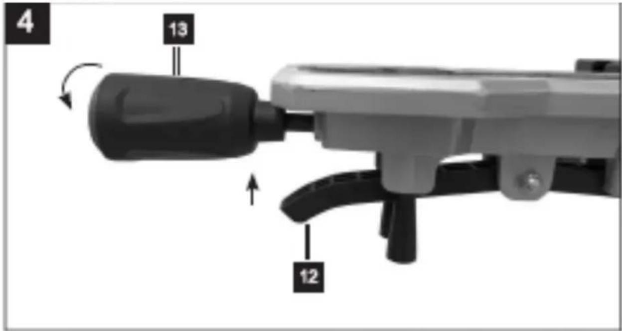
- To adjust the turntable (16), pull the indexed position lever (12) upwards with your index finger.
- Rotate the turntable (16) and pointer (14) to the desired angle on the scale (15) and lock in place by turning the turntable handle clockwise (13).
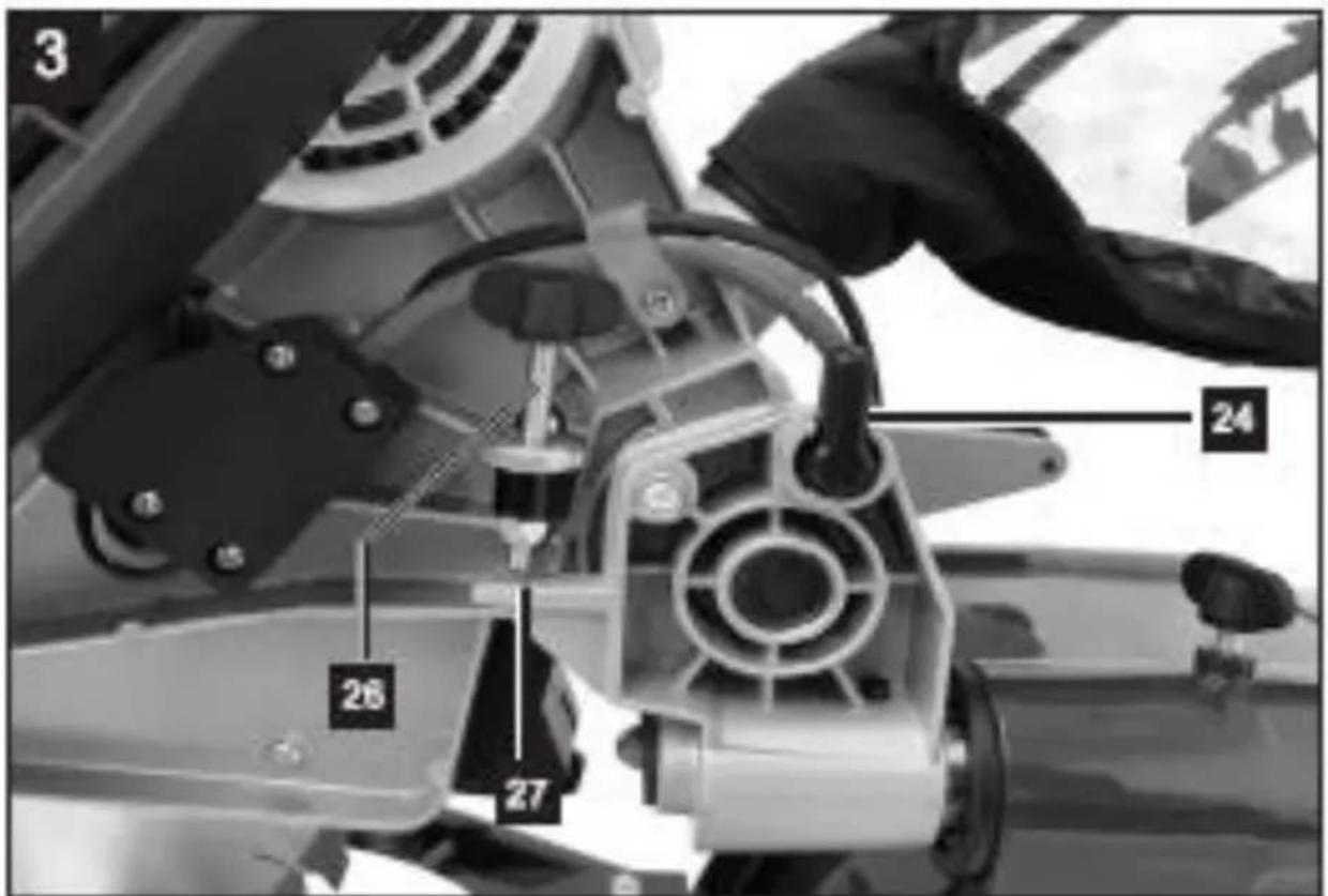
- Pressing the machine head (5) lightly downwards and pulling the locking pin (24-Fig.3) from the motor bracket at the same time disengages the saw from the lowest position.
- It is possible to secure the clamping device (8) to the left or right on the stationary saw bench (17).
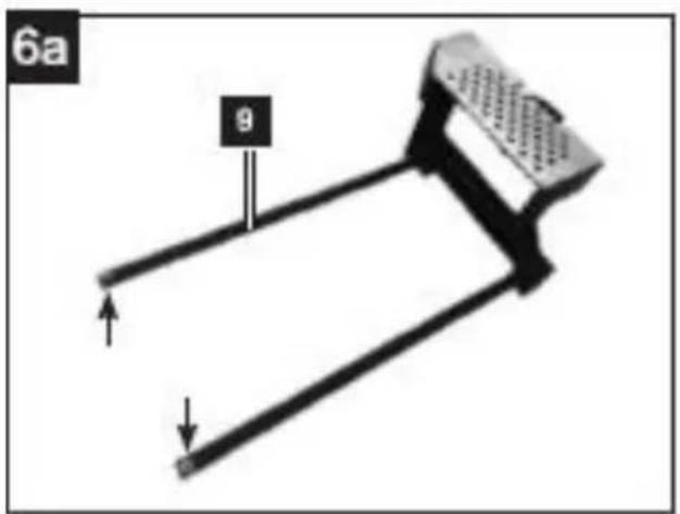
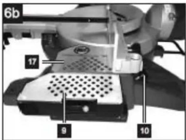
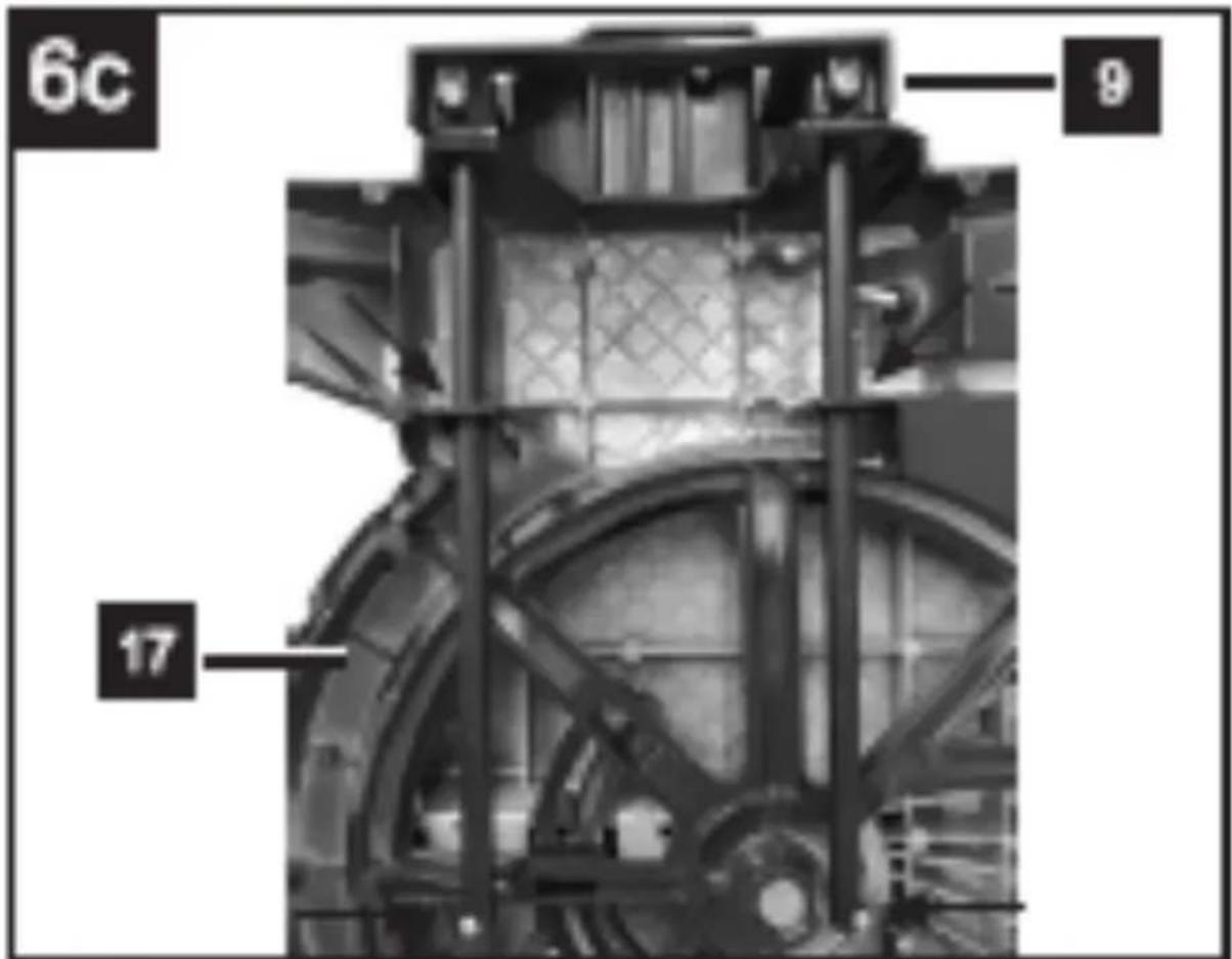
- Attach the workpiece supports (9) to the stationary saw bench (17) as shown in Figure 6a,b,c and push all the way through. Secure the shafts with the retaining springs to prevent them from slipping out accidentally. Then fasten in the desired position with the screws (10-Fig.6b).
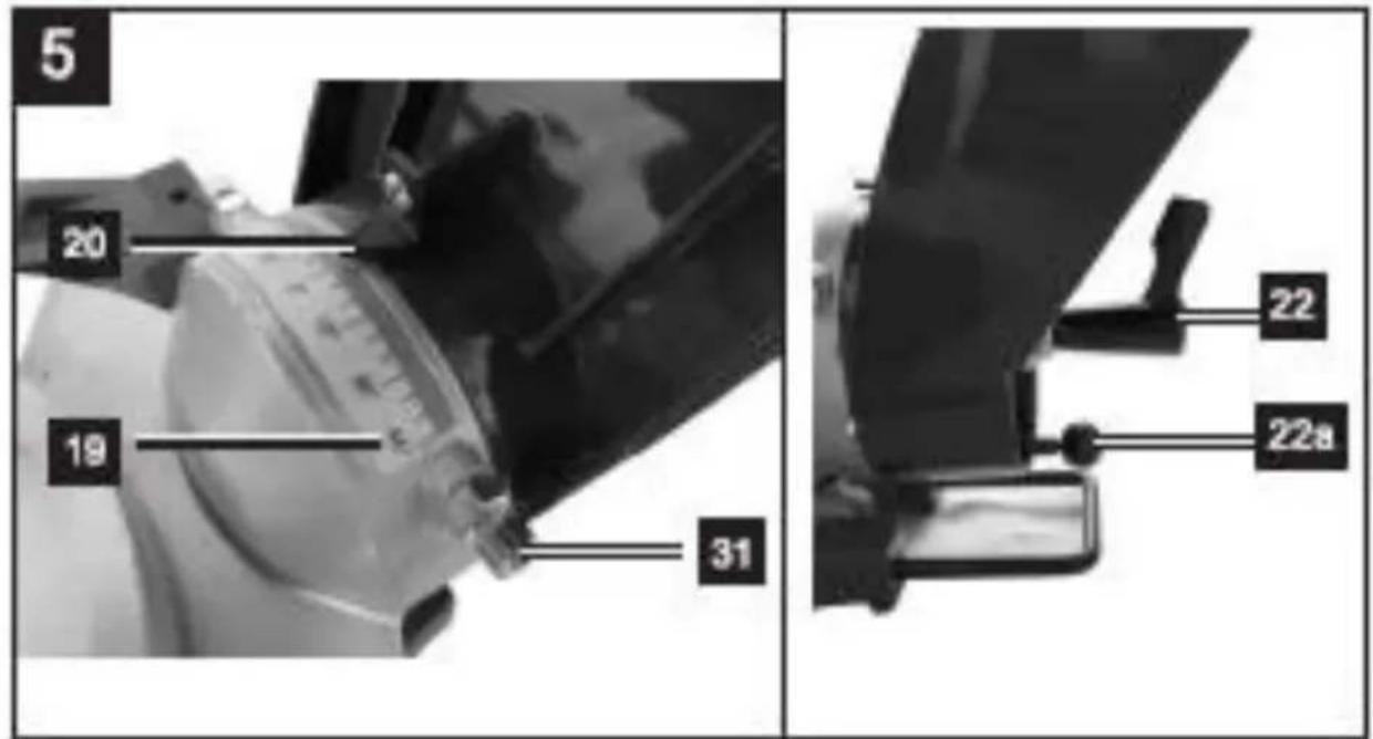
- It is possible to tilt the machine head (5) a max. 45° to the left by loosening the lock screw (22), to tilt the machine head (5) to the right to max. 45° the safety bolt (22a) must also be loosened.
9 OPERATING INSTRUCTIONS
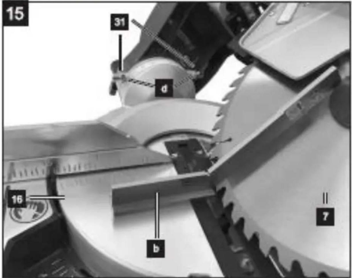
9.1 Precision adjustment of the stop for mitre cut 45° (Fig. 1, 3, 5, 15)

Remark : Requires an angle gauge (not included).
- Lower the machine head (5) and secure using the locking pin (24).
- Fix the turntable (16) in the 0° position.
- Loosen the lock screw (22) and use the handle (1) to angle the machine head (5) 45° to the left.
- Position the angle gauge (b) between the saw blade (7) and turntable (16).
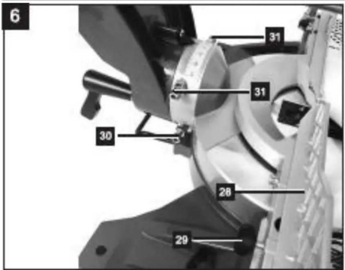
- Slacken the counternut (c). Adjust the adjustment screw (31) until the angle between the saw blade (7) and turntable (16) is precisely 45°.
- Retighten the counternut (d) to secure this setting.
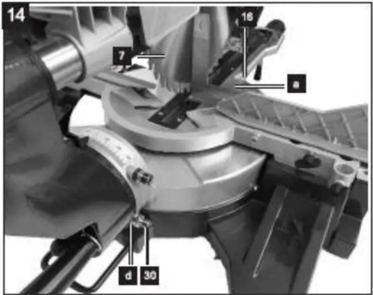
9.2 Precision adjustment of the stop for crosscut 90° (Fig. 3, 5, 14)

Remark : Requires an angle gauge (not included).
- Lower the machine head (5) and secure using the locking pin (24).
■ Loosen the lock screw (22). - Position the angle gauge (a) between the saw blade (7) and the turntable (16).
- Slacken the counternut (d). Adjust the adjustment screw (30) until the angle between the saw blade(7) and turntable (16) is 90°.
- Retighten the counternut (d) to secure this setting.
- Subsequently check the position of the angle indicator.
- If necessary loosen the pointer (20Fig.5) using a screwdriver, set to position 0^ on the scale (19-Fig.5) and re-tighten the pointer.
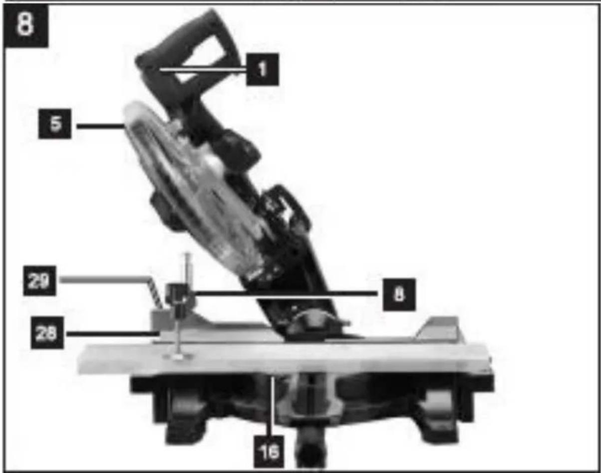
9.3 Making a straight cross cut at 90^ (machine head bevel at 0^ and turntable 0^ ) (Fig. 1, 2, 6, 7)
- In the case of cutting widths up to approx. 100 mm it is possible to fix the sliding function of the saw with the sliding bar lock screw (23) in the rear position.
- In this position the machine can be operated in cross cutting mode. If the cutting width is over 100 mm then it is necessary to ensure that the sliding bar lock screw (23) is loose and the machine head (5) can slide.
- Attention! For 90° mitre cuts, the moveable back fence (28) must be fixed in the inner position.
- Open the lock screw for back fence (29) on the moveable back fence (28) and push the moveable back fence (28) inwards.
- The moveable back fence (28) must be locked in a position far enough from the inner position that the distance between the back fence (28) and the saw blade (7) is no more than 5 mm.
- Before making the cut, check that no collision could occur between the back fence (28) and the saw blade (7).
- Tighten the lock screw for back fence (29) again, and move the machine head (5) to its upper position.
- Use the handle (1) to push back the machine head (5) and fix it in this position if required (dependent on the cutting width).
- Place the piece of wood to be cut at the back fence (28) and on the turntable (16).
- Lock the material with the clamping device (8) on the turntable (16) to prevent the material from moving during the cutting operation.
-
Release the lock switch (3) and press the ON/OFF switch (2) to start the motor.
-
With the sliding bar lock screw (23) fixed in place: use the handle (1) to move the machine head (5)
- Steadily and with light pressure downwards until the saw blade (7) has completely cut through the work piece.
- With the sliding bar lock screw (23) loosened, pull the machine head (5) all the way to the front. Lower the handle (1) to the very bottom by applying steady and light downward pressure.
- Now push the machine head (5) slowly and steadily to the very back until the saw blade (7) has completely cut through.
- When cutting is completed, move the machine head (5) back to its upper position and release the ON/OFF switch(2).
- Attention! The machine executes an upward stroke automatically due to the return spring, i.e. do not release the handle (1) after completing the cut; instead allow the machine head to move upwards slowly whilst applying light counter pressure.
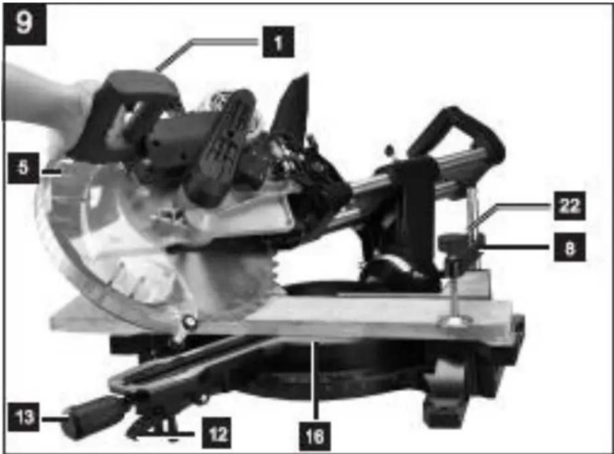
9.4 Straight cross cut 90^ with mitre angle (machine head bevel at 0^ and turntable between 0^-45^ ) (Fig. 1, 6, 7)
- The saw can be used to make crosscuts with a mitre angle of 0^ - 45^ to the left and 0^ - 45^ to the right.
- Loosen the sliding bar lock screw (29) on the back fence (28) and push the back fence (28) outwards.
- The back fence (28) must be locked in a position far enough from the inner position that the distance between the back fence (28) and the saw blade (7) is no more than 5 mm.
■ Before making the cut, check that no collision could occur between the back fence (28) and the saw blade (7). - Tighten the sliding bar lock screw (29) again.
- Use the turntable handle (13) to adjust the turntable (16) to the desired angle. The pointer (14) on the turntable (16) must match the desired angle on the scale (15) on the fixed saw table (17).
- Turn the turntable handle (13) clockwise to fix the turntable (16) in place.
■ Make the cut as described above.
9.5 Bevel cut 0°-45° (turntable at 0°) (Fig. 1, 2, 6, 8)
- The crosscut saw can be used to make bevel cuts of 0^ - 45^ in relation to the work face.
- Important! To make bevel cuts (inclined saw head), the back fence (28) must be fixed at the outer position.
- Loosen the lock screw for back fence (29) for the back fence (28) and push the back fence outwards.
- The back fence(28) must be fixed far enough away of the innermost position that the distance between it and the saw blade (7) amounts to a maximum of 5 mm.
■ Before making a cut, check that the back fence (28) and the saw blade (7) cannot collide. - Secure the lock screw for back fence (29) again, and move the machine head (5) to the top position.
- Fix the turntable (16) in the 0° position.
- Loosen the set screw (22-Fig.5) and use the handle (1) to angle the machine head (5) to the left, until the pointer (20) indicates the desired angle measurement on the scale (19), re-tighten the fixing screw (22-Fig.5).
■ Make the cut as described above.
9.6 Bevel cut 0^ -45° and mitre cut 0^ -45° (machine head at 0^ -45° and turntable 0^ -45°) (Fig. 1, 2, 6, 9)

Remark: The saw can be used to make bevel cuts to the left and right of 0^-45^ in relation to the work face, and at the same time 0^-45^ to the left or 0^-45^ to the right in relation to the back fence(double mitre cut).
- Important. To make miter cuts (inclined saw head), the back fence(28) must be fixed at the outer position.
- Loosen the lock screw for back fence (29) for the back fence(28) and push the back fence outwards.
- The back fence(28) must be fixed far enough away of the innermost position that the distance between the back fence(28) and the saw blade (7) amounts to a maximum of 5 mm.
■ Before making a cut, check that the back fence(28) and the saw blade (7) cannot collide. - Secure the lock screw for back fence (29) again, move the machine head (5) to its upper position.
- Release the turntable (16) by loosening the handle (13) and pulling the indexed position lever (12) up.
■ Using the turntable handle (13), set the turntable (16) to the desired angle.
■ Re-tighten the turntable handle (13) in order to secure the turntable. - Undo the locking screw (22-Fig.5) and use the handle (1) to tilt the machine head (5) to the left or the right top the required angle.
■ Re-tighten the lock screw (22).
■ Make the cut as described above.
9.7 Limiting the cutting depth (Fig. 3)
The cutting depth can be infinitely adjusted using the screw for cutting depth limiter (26). To do this loosen the knurled nut on the screw for cutting depth limiter (26). Turn the screw for cutting depth limiter (26) in or out to set the required cutting depth. Then re-tighten the knurled nut on the screw for cutting depth limiter (26). Check the setting by completing a test cut.
9.8 Sawdust bag (Fig. 2)
The saw is equipped with a sawdust bag (21) for sawdust and chips. Squeeze together the metal ring on the dust bag and attach it to the outlet opening in the motor area. The sawdust bag (21) can be emptied by means of a zipper at the bottom.
Alternatively a specialized vacuum cleaner can also be used, possibly using an adapter.
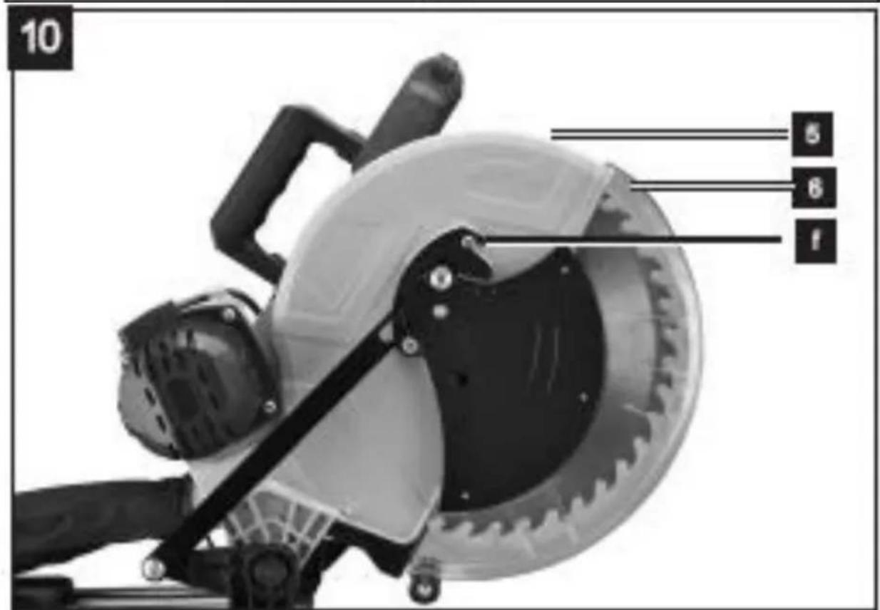
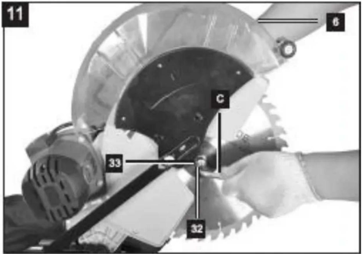
9.9 Changing the saw blade (Fig. 10,11,12 and 13)

Important: Remove the power plug! Wear safety gloves when changing the saw blade. Risk of injury!
■ Swing up the machine head (5).
■ Loosen the screw (f) of the flange cover so that it is free to move.
- Swing up the moveable blade guard (6) to the point where the recess in the moveable blade guard (6) is above the flange screw (32).
- Insert the hexagonal key (c) in the flange screw (32).
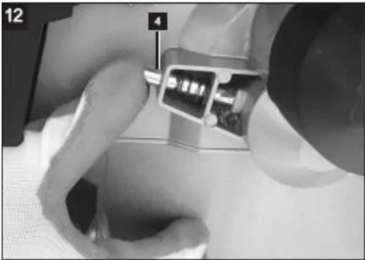
- Firmly press the saw shaft lock (4) and slowly rotate the flange screw (32) in clockwise direction.
■ The saw shaft lock (4) engages after no more than one rotation.
- Now, using a little more force, slacken the flange screw (32) in the clockwise direction.
- Turn the flange bolt (32) right out and remove the outer flange (33).
POWX075751DB EN
■ Take the saw blade (7) off the inner flange (34) and pull out downwards.
- Carefully clean the flange screw (32), outer flange (33) and inner flange (34).
- Fit and fasten the moveable blade guard (6) in reverse order.
- Important! The cutting angle of the teeth, in other words the direction of rotation of the saw blade (7) must coincide with the direction of the arrow on the housing.
- Move the guide bar into position and tighten the screw (f) again.
■ Before continuing your work make sure that all safety devices are in good working condition.

Important: Every time that you change the saw blade (7), check to see that it spins freely in the table insert (11) in both perpendicular and 45° angle settings.
Important: The work to change and align the saw blade (7) must be carried out correctly.
10 TECHNICAL DATA
| Nominal Voltage | 220-240V ~ 50 Hz |
| Power rating | 2000 W (S6 40%) |
| No load speed | 3800 min-1 |
| Protection class | II |
| Blade size | 305 mm x 30 mm x 2,8mm |
11 CUTTING CAPACITY
| Worktable tilting angle | Head tilting angle | Height x width (mm) |
| 90° | 90° | 105 x 330 mm |
| 45° | 90° | 105 x 230 mm |
| 90° | 45° | 60 x 330 mm (left) |
| 90° | 45° | 33 x 330 mm (right) |
| 45° | 45° | 60 x 230 mm (left) |
| 45° | 45° | 33 x 230 mm (right) |
12 NOISE
Noise emission values measured according to relevant standard. (K=3)
| Acoustic pressure level LpA | 95 dB(A) |
| Acoustic power level LwA | 108 dB(A) |

ATTENTION! Wear hearing protection when sound pressure is over 85 dB(A).
13 STORAGE
- Thoroughly clean the whole machine and its accessories.
- Store it out of the reach of children, in a stable and secure position, in a cool and dry place, avoid too high and too low temperatures.
- Protect it from exposure to direct sunlight. Keep it in the dark, if possible.
- Don't keep it in plastic bags to avoid humidity build-up.
14 TROUBLE SHOOTING
| PROBLEM | POSSIBLE CAUSE | SOLUTION |
| Motor does not run. | No electricity arrives at the machine.The motor is overloaded or overheated. | Check the power supply and the power line.Allow the machine to run idle for about 2 minutes to cool down. |
| Vibrations are too strong. | Screws or parts are loose.The mitre saw is not correctly mounted.Work piece is not properly supported. | Tighten all screws.Mount the mitre saw correctly.Secure the work piece. |
15 WARRANTY
- This product is warranted for a 36-month period effective from the date of purchase by the first user.
- This warranty covers all material or production flaws excluding : batteries, chargers, defective parts subject to normal wear & tear such as bearings, brushes, cables, and plugs, or accessories such as drills, drill bits, saw blades, etc. ; damage or defects resulting from maltreatment, accidents or alterations; nor the cost of transportation.
- Damage and/or defects resulting from inappropriate use also do not fall under the warranty provisions.
- We also disclaim all liability for any bodily injury resulting from inappropriate use of the tool.
- Repairs may only be carried out by an authorized customer service centre for Powerplus tools.
- You can always obtain more information at the number 00 32 3 292 92 90.
- Any transportation costs shall always be borne by the customer, unless agreed otherwise in writing.
- At the same time, no claim can be made on the warranty if the damage of the device is the result of negligent maintenance or overload.
- Definitely excluded from the warranty is damage resulting from fluid permeation, excessive dust penetration, intentional damage (on purpose or by gross carelessness), inappropriate usage (use for purposes for which the device is not suitable), incompetent usage (e.g. not following the instructions given in the manual), inexpert assembly, lightning strike, erroneous net voltage. This list is not exhaustive.
- Acceptance of claims under warranty can never lead to the prolongation of the warranty period nor commencement of a new warranty period in case of a device replacement.
- Devices or parts which are replaced under the warranty therefore remain the property of Varo NV.
- We reserve the right to reject a claim whenever the purchase cannot be verified or when it is clear that the product has not been properly maintained. (Clean ventilation slots, carbon brushes serviced regularly, etc.).
- Your purchase receipt must be kept as proof of date of purchase.
- Your appliance must be returned undismantled to your dealer in an acceptably clean state, (in its original blow-moulded case if applicable to the unit), accompanied by proof of purchase.
16 ENVIRONMENT

Should your appliance need replacement after extended use, do not discard it with the household rubbish but dispose of it in an environmentally safe way. Waste produced by electrical machine items should not be handled like normal household rubbish. Please recycle where recycle facilities exist. Check with your Local Authority or retailer for recycling advice.
17 DECLARATION OF CONFORMITY


VARO N.V. - Vic. Van Rompuy n.v., Joseph Van Instraat 9 - BE2500 Lier - BELGIUM, declares that,
product: Double Bevel Sliding Mitre Saw
trade mark: POWERplus
model: POWX075751DB
is in conformity with the essential requirements and other relevant provisions of the applicable European Directives, based on the application of European harmonized standards. Any unauthorized modification of the apparatus voids this declaration.
European Directives (including, if applicable, their amendments up to the date of signature);
2011/65/EU
2006/42/EC
2014/30/EU
European harmonized standards (including, if applicable, their amendments up to the date of signature);
EN62841-1:2015
EN62841-3-9:2015
EN55014-1:2017
EN55014-2:2015
EN IEC61000-3-2 : 2019
EN IEC61000-3-11 : 2019
Keeper of the Technical Documentation: Philippe Vankerkhove, VARO – Vic. Van Rompuy N.V.
The undersigned acts on behalf of the company CEO,
Mertens Ludo
Ludo Mertens
Regulatory Affairs – Compliance Manager
28/10/2021, Lier - Belgium
1 EINSATZBEREICH 3
28/10/2021, Lier - Belgium
1 APLICACIÓN ....3
28/10/2021, Lier - Belgium
1 APPLICAZIONE 3
Regulatory Affairs – Compliance Manager
28/10/2021, Lier - Belgium
28/10/2021, Lier - Belgium
28/10/2021, Lier - Belgium
3 FÖRPACKNINGSINNEHÅLL 3
4 SYMBOLER....4
5 ALLMÄNNA SÄKERHETSANVISNINGAR FÖR ELEKTRISKA VERKTYG....4
3 FÖRPACKNINGSINNEHÅLL
28/10/2021, Lier - Belgium
1 ΕΦΑΡΜΟΓΗ 3
2 OPIS (SLIKA A I B)....3
3 POPIS SADRŽAJA PAKETA 3
4 SIMBOLI 4
5 OPĆA UPOZORENJA O SIGURNOSTI RUKOVANJA ELEKTRIČNIM ALATIMA......4
1 List pile: ∅ 305 x 30 x 2,8mm (40T)

28/10/2021, Lier - Belgium
1 PRIMENA 3
2 OPIS (SL. A & B)....3
3 SPISAK SADRŽAJA PAKOVANJA 3
4 SIMBOLI 4
5 OPŠTA BEZBEDNOSNA UPUTSTVA ZA ELEKTRIČNE ALATE .4
5.1 Radna oblast 4
28/10/2021, Lier - Belgium
2 POPIS (OBR. A A B)....3
3 OBSAH BALENIA....3
4 SYMBOLY 4
5 VŠEOBECNÉ BEZPEČNOSTNÉ VAROVANIA PRE ELEKTRICKÉ NÁRADIE 4
5.1 Pracovná plocha....4
28/10/2021, Lier - Belgium
1 DOMENII DE UTILIZARE....3
2 DESCRIERE (FIG. A & B)....3
3 CONTINUTUL PACHETULUI .... 3
4 SIMBOLURI....4
5 AVERTISMENTE GENERALE DE SIGURANTĂ PRIVIND APARATELE ELECTRICE ....4
5.1 Zona de lucru 4
28/10/2021, Lier - Belgium
1 ZASTOSOWANIE....3
2 OPIS (RYC. A I B) 3
3 SPIS CZEŚCI....3
4 OZNACZENIA 4
5 OGÓLNE ZASADY BEZPIECZNEJ PRACY ELEKTRONARZĘDZIAMI....4
28/10/2021, Lier - Belgium
28/10/2021, Lier - Belgium
1 ПРЕДНАЗНАЧЕНИЕ НА ЕЛЕКТРОИНСТРУМЕНТА....3
natural_image
Yellow and black industrial cutting machine with blade and workpiece (no visible text or symbols)varo
WWW.VARO.COM
DESIGNED AND MARKETED BY VARO
©copyright by varo
VARO - VIC. VAN ROMPUY nv
JOSEPH VAN INSTRAAT 9 - 2500 LIER - BELGIUM
OFFICES:


- POWERPLUS® HIGH QUALITY TOOLS
- POWX075751DB EN
- DOUBLE BEVEL SLIDING MITRE SAW 2000W-305MM POWX075751DB
- APPLICATION
- WARNING! For your own safety, read this manual and the general safety instructions carefully before using the appliance. Your power tool should only be given to other users together with these instructions.
- DESCRIPTION (FIG A & B)
- PACKAGE CONTENT LIST
- WARNING! Packaging materials are not toys! Children must not play with plastic bags! There is a danger of suffocation!
- SYMBOLS
- GENERAL POWER TOOL SAFETY WARNINGS
- Working area
- Electrical safety
- Personal safety
- Power tools use and care
- Service
- ADDITIONAL SAFETY INSTRUCTIONS
- ADDITIONAL SAFETY INSTRUCTIONS FOR LASERS
- Warning! The laser beam potentially causes eye damage. Do not look or stare into the laser beam.
- ASSEMBLY
- Disconnect the power plug before carrying out any adjustments or maintenance.
- Assembling the saw (Fig. 1 - 6)
- OPERATING INSTRUCTIONS
- Precision adjustment of the stop for mitre cut 45° (Fig. 1, 3, 5, 15)
- Remark : Requires an angle gauge (not included).
- Precision adjustment of the stop for crosscut 90° (Fig. 3, 5, 14)
- Making a straight cross cut at 90° (machine head bevel at 0° and turntable 0° ) (Fig. 1, 2, 6, 7)
- Straight cross cut 90° with mitre angle (machine head bevel at 0° and turntable between 0°-45^° ) (Fig. 1, 6, 7)
- Bevel cut 0°-45° (turntable at 0°) (Fig. 1, 2, 6, 8)
- Limiting the cutting depth (Fig. 3)
- Sawdust bag (Fig. 2)
- Changing the saw blade (Fig. 10,11,12 and 13)
- NOISE
- STORAGE
- TROUBLE SHOOTING
- WARRANTY
- ENVIRONMENT
- DECLARATION OF CONFORMITY
- FÖRPACKNINGSINNEHÅLL
Brand : PowerPlus
Model : POWX075751DB
Category : Saw