
CCG 18-125-7 AS - Grinder Fein - Free user manual and instructions
Find the device manual for free CCG 18-125-7 AS Fein in PDF.
| Product type | Cordless angle grinder |
| Brand | Fein |
| Model | CCG 18-125-7 AS |
| Power supply | 18 V lithium-ion battery, AMPShare system |
| Max disc diameter | 125 mm |
| Weight (without battery) | Approx. 2.5 kg |
| Brake | Electronic brake (quick disc stop) |
| Restart protection | Yes |
| Overload protection | Electronic |
| Soft start | Yes |
| Clamping system | X-LOCK (tool-free) or clamping flange (depending on version) |
| Gear head rotation | 3 positions (tool-adjustable) |
| Auxiliary handle | Yes, removable |
| Protective guard | Type A (cutting) and Type B (grinding) |
| Applications | Cutting, grinding, sanding, brushing, stone drilling |
| Maintenance | Blow out ventilation slots with dry compressed air |
| Cleaning | Soft, dry brush for ventilation openings |
| Compatible accessories | Grinding discs, cutting discs, flap discs, brushes, sanding pads, diamond core bits |
| Warranty | In accordance with legal regulations and Fein manufacturer declaration |
| Certifications | CE, UKCA |
Frequently Asked Questions - CCG 18-125-7 AS Fein
User questions about CCG 18-125-7 AS Fein
0 question about this device. Answer the ones you know or ask your own.
Ask a new question about this device
Download the instructions for your Grinder in PDF format for free! Find your manual CCG 18-125-7 AS - Fein and take your electronic device back in hand. On this page are published all the documents necessary for the use of your device. CCG 18-125-7 AS by Fein.
USER MANUAL CCG 18-125-7 AS Fein
natural_image
Two ProCore 900 electric surge absorber tools shown from different angles (no text or symbols visible on the devices themselves)3 41 01 403 06 0 2024-01-17

FEIN


2
CCG18-125-7 AS (**) CCG18-125-7 X AS (**)
7 122 13... 7 122 14...
| U | V= | 18 18 |
| n0 | /min, min -1 , rpm, r/min 11000 11000 |


| kg | 1,7 / 1,6 | 1,8 / 1,7 | |
| LpA | dB | 85,0 | 95,0 |
| KpA | dB 3 3 | ||
| LwA | dB | 93,0 103,0 | |
| KwA | dB 3 3 | ||
| αh,AG | m/s2 | 7,0 | 9,0 |
| αh,DS | m/s2 | 3,5 | 2,5 |
| Kg | m/s2 | 1,5 | 1,5 |
| GBA 18V2 Ah | GBA 18V4 Ah | GBA 18V5 Ah | ProCORE 18V4 Ah | ProCORE 18V8 Ah | ||
| AMP Share I | ||||||
| Powered by BOSCH | ||||||
| Lithium Ion | Lithium Ion | Lithium Ion | Lithium Ion | Lithium Ion | ||
| U | V= | 18 | 18 | 18 | 18 | 18 |
| kg | 0,35 | 0,60 | 0,60 | 0,52 | 0,96 | |

GAL 1880 CV, GAL 18V-160

1
1


4
flowchart
graph TD
    A["Component 8"] --> B["Motor"]
    C["Component 11"] --> B
    D["Component 15"] --> B
    E["Component 13"] --> B
    F["Component 10"] --> B
    G["Component 6"] --> B
    H["Component 13"] --> I["Hand"]
    J["Component 14"] --> I
    K["I/O"] --> L["Switch symbol"]
    M["CCG18-125-7 AS (**)"] --> N["7"]
    O["I+"] --> P["+"]
    Q["Document icon"] --> R["Arrow pointing to component 13"]


flowchart
graph TD
    A["Component 9"] --> B["Motor"]
    C["Component 11"] --> B
    D["Component 15"] --> B
    E["Component 13"] --> B
    F["Component 6"] --> G["Motor"]
    H["Component 10"] --> G
    I["I/O"] --> J["Motor"]
    K["Component 7"] --> L["Motor"]
    M["Component 13 12 14"] --> L
    N["i+"] --> O["Document Icon"]
    P["Document Icon"] --> Q["Arrow Down"]
    style A fill:#f9f,stroke:#333
    style C fill:#f9f,stroke:#333
    style D fill:#f9f,stroke:#333
    style E fill:#f9f,stroke:#333
    style F fill:#f9f,stroke:#333
    style H fill:#f9f,stroke:#333
    style I fill:#f9f,stroke:#333
    style K fill:#f9f,stroke:#333
    style M fill:#f9f,stroke:#333
    style N fill:#f9f,stroke:#333


OBJ BUCH-0000000540-001.book Page 6 Tuesday, January 16, 2024 2:55 PM


6


8


The image contains a graphical symbol and no textual content. Therefore, the correct OCR output is an empty string.
(No text to output)


OBJ_BUCH-0000000540-001.book Page 10 Tuesday, January 16, 2024 2:55 PM


10


OBJ_BUCH-0000000540-001.book Page 11 Tuesday, January 16, 2024 2:55 PM
11


12


14


OBJ_BUCH-0000000540-001.book Page 15 Tuesday, January 16, 2024 2:55 PM
15


CCG18-125-7 X AS (**)


natural_image
Technical line drawing of a mechanical tool or robotic arm (no text or symbols visible)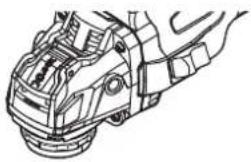
natural_image
Technical line drawing of a mechanical assembly (no text or symbols)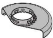
CCG18-125-7 AS (**) : 3 13 24 000 40 9
CCG18-125-7 X AS ( ** ): 3 13 24 000 44 1
CCG18-125-7 AS (**) : 3 13 24 000 35 1
CCG18-125-7 X AS (**) : 3 13 24 000 14 2

CCG18-125-7 AS (**) : 3 13 24 000 10 4
CCG18-125-7 AS (**) : 3 13 24 000 10 6


CCG18-125-7 AS (**) : 6 38 02 197 00 0
CCG18-125-7 AS (**) : 6 29 10 022 00 2
natural_image
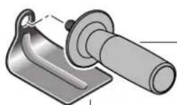
Technical illustration of a mechanical component with a flanged shaft and mounting bracket (no text or symbols)3 13 24 000 11 0
3 02 29 216 00 5
Translation of the Original Instructions.
Symbols, abbreviations and terms used.
| Symbol, character Explanation | |
| Make sure to read the enclosed documents such as the Instruction Manual and the General Safety Instructions. | |
| AMPShare is the shared battery system that lets you run many tools from many pro brands on just one battery. | |
| XLOCK | Toolless clamping system for application tools and angle grinders. |
| General prohibition sign. This action is prohibited. | |
| Do not touch the rotating parts of the power tool. | |
| Observe the instructions in the text or graphic opposite! | |
| Before commencing this working step, remove the battery from the power tool. Otherwise there may be danger of Injury caused by unintentional starting of the power tool. | |
| Use eye protection during operation. | |
| Use ear protection during operation. | |
| Use protective gloves during operation. | |
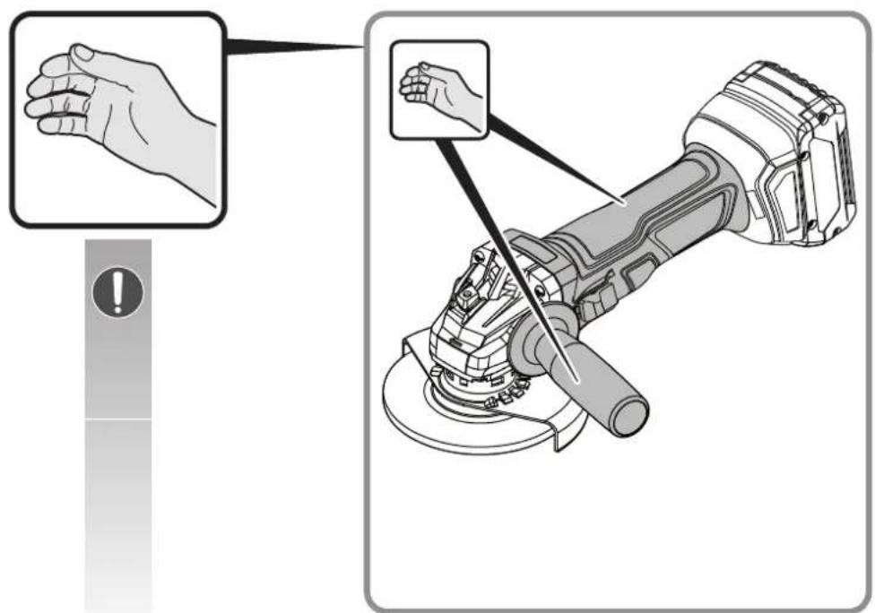
| Always operate the power tool with two hands. | |
| Cutting applications with wheel guard are prohibited. | |
| Do not charge damaged batteries. | |
| Protect the battery against heat, e.g., against continuous intense sunlight, fire, debris, water, and moisture. | |
| Observe the Information In the adjacent text! | |
| A surface that can be touched may be very hot and thus hazardous. | |
| Gripping surface | |
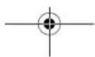
| Switching on | |
| Switching off | |
| Locked | |
| Not locked | |
| Additional information. | |
| See section “Operating Instructions” | |


en
31
| Symbol, character Explanation | |
 | Confirms the conformity of the power tool with the directives of the European Community. |
| [Z6K4] | Confirms the conformity of the power tool with the directives of Great Britain (England, Wales, Scotland). |
 | This sign indicates a possible dangerous situation that could cause severe or fatal injury. |
 | Recycling symbol: designates recyclable materials |
 | Worn out power tools and other electrotechnical and electrical products should be sorted separately for environmental-friendly recycling. |
 | Identifies recyclable packaging and products that must be collected and disposed of separately. |
| [SZ46] | Battery type |
 | Charger type |
| (**) May contain numbers and letters | |
| (Ax - Zx) Marking for internal purposes | |
| (**) May contain numbers and letters | |
| (Ax - Zx) Marking for internal purposes |
| Character Unit of measurement, international | Explanation | |
| n0 | /min, min -1 , rpm, r/min | Rated no-load speed |
| UV Rated voltage | ||
| M... | mm Size of metric thread | |
| ∅ mm Diameter of a round part | ||
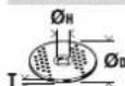
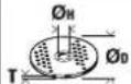 | mm | ∅D=Max. diameter of grinding/cutting disc∅H=Diameter of mounting holeT=Thickness of grinding/cutting disc |
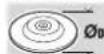
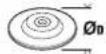 | mm | ∅D=Max. sanding pad diameter |
 | mm M=Thread for clamping flangeI=Length of mounting thread | |
 | mm | ∅D=max. cup brush diameterM=Thread for clamping flange / application toolT=max. wire length |
 | mm | ∅D=Max. diameter of diamond core bitM=Thread for clamping flange / application tool |
 | kg Weight of the power tool according to EPTA procedure 01without battery and application tool, and with wheel guard type A / B | |
 | kg Weight of the battery | |
| LDA | dB Sound pressure level | |
 | dB Sound power level | |
32
en
| Character Unit of measurement, international | Explanation |
| K... | |
| a | m/s 2 |
| ah,AG | m/s 2 |
| ah,DS | m/s 2 |
| m, s, kg, A, mm, V, W, N, °C, dB, min, m/s 2 | |
| Basic and derived units of measurement from the international system of units SI. |
For your safety.
WARNING
Read all safety warnings and all instructions. Failure to follow the
warnings and instructions may result in electric shock, fire and/or serious injury.
Save all warnings and instructions for future reference.

Do not use this power tool before you have thoroughly read and completely understood this Instruction Manual and the enclosed "General
Safety Instructions" (document number
3 41 30 465 06 0). The documents mentioned should be kept for later use and enclosed with the power tool, should it be passed on or sold.
Please also observe the relevant national industrial safety regulations.
Intended use of the power tool:
The hand-guided, battery-operated angle grinder is intended for cutting, roughing and brushing of metal and stone materials as well as for drilling stone materials with diamond core bits without the use of water.
For cutting with bonded abrasives, a special cut-off wheel guard must be used.
When cutting in stone, provide for sufficient dust extraction.
With approved sanding tools, the machine can be used for sanding with sanding discs.
The power tool must not be used for grinding concrete.
Safety warnings common for grinding, sanding, wire brushing or cutting-off operations
This power tool is intended to function as a grinder, sander, wire brush, hole cutter or cut-off tool. Read all safety warnings, instructions, illustrations and specifications provided with this power tool. Failure to follow all instructions listed below may result in electric shock, fire and/or serious injury.
Operations such as polishing are not to be performed with this power tool. Operations for which the power tool was not designed may create a hazard and cause personal injury.
Do not convert this power tool to operate in a way which is not specifically designed and specified by the tool manufacturer. Such a conversion may result in a loss of control and cause serious personal injury.
Do not use accessories which are not specifically designed and specified by the tool manufacturer. Just because the accessory can be attached to your power tool, it does not assure safe operation.
The rated speed of the accessory must be at least equal to the maximum speed marked on the power tool.
Accessories running faster than their rated speed can break and fly apart.
The outside diameter and the thickness of your accessory must be within the capacity rating of your power tool. Incorrectly sized accessories cannot be adequately guarded or controlled.
The dimensions of the accessory mounting must fit the dimensions of the mounting hardware of the power tool. Accessories that do not match the mounting hardware of the power tool will run out of balance, vibrate excessively and may cause loss of control.
Do not use a damaged accessory. Before each use inspect the accessory such as abrasive wheels for chips and cracks, backing pad for cracks, tear or excess wear, wire brush for loose or cracked wires. If power tool or accessory is dropped, inspect for damage or install an undamaged accessory. After inspecting and installing an accessory, position yourself and bystanders away from the plane of the rotating accessory and run the power tool at maximum no-load speed for one minute. Damaged accessories will normally break apart during this test time.
Wear personal protective equipment. Depending on application, use face shield, safety goggles or safety glasses. As appropriate, wear dust mask, hearing protectors, gloves and workshop apron capable of stopping small abrasive or workpiece fragments. The eye protection must be capable of stopping flying debris generated by various applications. The dust mask or respirator must be capable of filtrating particles generated by the particular application. Prolonged exposure to high intensity noise may cause hearing loss.
Keep bystanders a safe distance away from work area. Anyone entering the work area must wear personal protective equipment. Fragments of workpiece or of a broken accessory may fly away and cause injury beyond immediate area of operation.
Hold the power tool by insulated gripping surfaces only, when performing an operation where the cutting accessory may contact hidden wiring. Cutting accessory contacting a "live" wire may make exposed metal parts of the power tool "live" and could give the operator an electric shock.
Never lay the power tool down until the accessory has come to a complete stop. The spinning accessory may grab the surface and pull the power tool out of your control.
Do not run the power tool while carrying it at your side. Accidental contact with the spinning accessory could snag your clothing, pulling the accessory into your body.
Regularly clean the power tool's air vents. The motor's fan will draw the dust inside the housing and excessive accumulation of powdered metal may cause electrical hazards.
Do not operate the power tool near flammable materials. Sparks could ignite these materials.
Do not use accessories that require liquid coolants. Using water or other liquid coolants may result in electrocution or shock.
Kickback and related warnings
Kickback is a sudden reaction to a pinched or snagged rotating wheel, backing pad, brush or any other accessory. Pinching or snagging causes rapid stalling of the rotating accessory which in turn causes the uncontrolled power tool to be forced in the direction opposite of the accessory's rotation at the point of the binding.
For example, if an abrasive wheel is snagged or pinched by the workpiece, the edge of the wheel that is entering into the pinch point can dig into the surface of the material causing the wheel to climb out or kick out. The wheel may either jump toward or away from the operator, depending on direction of the wheel's movement at the point of pinching. Abrasive wheels may also break under these conditions.
Kickback is the result of power tool misuse and/or incorrect operating procedures or conditions and can be avoided by taking proper precautions as given below.
Maintain a firm grip with both hands on the power tool and position your body and arm to allow you to resist kickback forces. Always use auxiliary handle, if provided, for maximum control over kickback or torque reaction during start-up. The operator can control torque reactions or kickback forces, if proper precautions are taken.
Never place your hand near the rotating accessory. Accessory may kickback over your hand.
Do not position your body in the area where power tool will move if kickback occurs. Kickback will propel the tool in direction opposite to the wheel's movement at the point of snagging.
Use special care when working corners, sharp edges, etc. Avoid bouncing and snagging the accessory. Corners, sharp edges or bouncing have a tendency to snag the rotating accessory and cause loss of control or kickback.
Do not attach a saw chain woodcarving blade, segmented diamond wheel with a peripheral gap greater than 10 mm or toothed saw blade. Such blades create frequent kickback and loss of control.
Safety warnings specific for grinding and cutting-off operations
Use only wheel types that are specified for your power tool and the specific guard designed for the selected wheel. Wheels for which the power tool was not designed cannot be adequately guarded and are unsafe.
The grinding surface of centre depressed wheels must be mounted below the plane of the guard lip. An improperly mounted wheel that projects through the plane of the guard lip cannot be adequately protected.
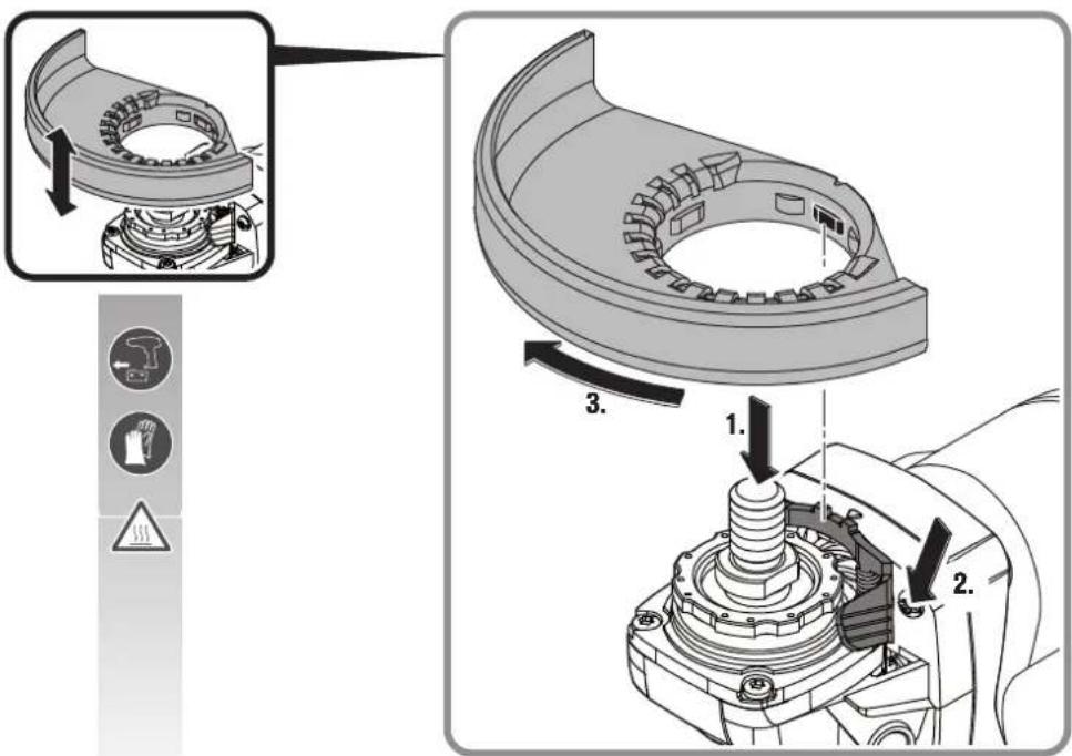
The guard must be securely attached to the power tool and positioned for maximum safety, so the least amount of wheel is exposed towards the operator. The guard helps to protect the operator from broken wheel fragments, accidental contact with wheel and sparks that could ignite clothing.
Wheels must be used only for specified applications. For example: do not grind with the side of cut-off wheel. Abrasive cut-off wheels are intended for peripheral grinding, side forces applied to these wheels may cause them to shatter.
Always use undamaged wheel flanges that are of correct size and shape for your selected wheel. Proper wheel flanges support the wheel thus reducing the possibility of wheel breakage. Flanges for cut-off wheels may be different from grinding wheel flanges.
Do not use worn down wheels from larger power tools. A wheel intended for larger power tools is not designed for the higher speeds of smaller power tools and may burst.
When using dual purpose wheels always use the correct guard for the application being performed. Failure to use the correct guard may not provide the desired level of guarding, which could lead to serious injury.
Additional safety warnings specific for cutting off operations
Do not "jam" the cut-off wheel or apply excessive pressure. Do not attempt to make an excessive depth of cut. Overstressing the wheel increases the loading and susceptibility to twisting or binding of the wheel in the cut and the possibility of kickback or wheel breakage.
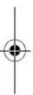
Do not position your body in line with and behind the rotating wheel. When the wheel, at the point of operation, is moving away from your body, the possible kickback may propel the spinning wheel and the power tool directly at you.
When wheel is binding or when interrupting a cut for any reason, switch off the power tool and hold it motionless until the wheel comes to a complete stop. Never attempt to remove the cut-off wheel from the cut while the wheel is in motion otherwise kickback may occur. Investigate and take corrective action to eliminate the cause of wheel binding.
Do not restart the cutting operation in the workpiece. Let the wheel reach full speed and carefully re-enter the cut. The wheel may bind, walk up or kickback if the power tool is restarted in the workpiece.


en
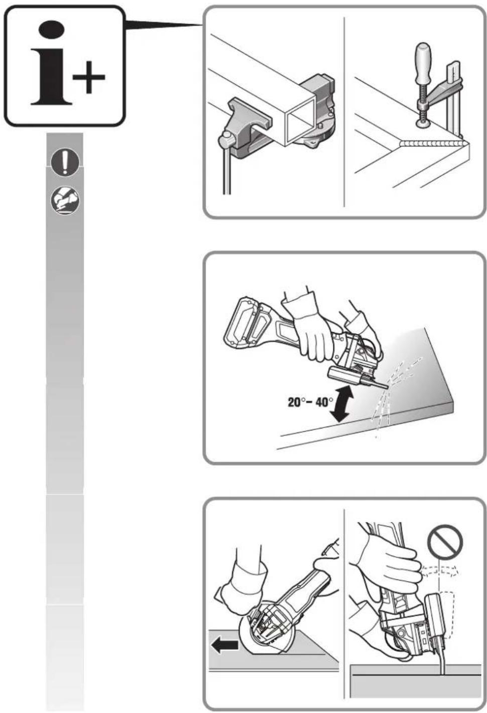
Support panels or any oversized workpiece to minimize the risk of wheel pinching and kickback. Large workpieces tend to sag under their own weight. Supports must be placed under the workpiece near the line of cut and near the edge of the workpiece on both sides of the wheel.
Use extra caution when making a "pocket cut" into existing walls or other blind areas. The protruding wheel may cut gas or water pipes, electrical wiring or objects that can cause kickback.
Do not attempt to do curved cutting. Overstressing the wheel increases the loading and susceptibility to twisting or binding of the wheel in the cut and the possibility of kickback or wheel breakage, which can lead to serious injury.
Safety warnings specific for sanding operations Use proper sized sanding disc paper. Follow manufacturers recommendations, when selecting sanding paper. Larger sanding paper extending too far beyond the sanding pad presents a laceration hazard and may cause snagging, tearing of the disc or kickback.
Safety warnings specific for wire brushing operations
Be aware that wire bristles are thrown by the brush even during ordinary operation. Do not overstress the wires by applying excessive load to the brush. The wire bristles can easily penetrate light clothing and/or skin. If the use of a guard is specified for wire brushing, do not allow any interference of the wire wheel or brush with the guard. Wire wheel or brush may expand in diameter due to work load and centrifugal forces.
Further safety warnings
When grinding thin metal sheet or other well vibrating structures with large surface area, take appropriate measures such as using heavy flexible damping mats. Otherwise, a much higher overall noise emission may occur than the specified noise emission of the power tool. Also consider the Increased noise emission for risk assessment of noise exposure and for selection of appropriate hearing protection.
Use elastic spacers when these are provided with the grinding accessory.
Make sure that the application tools are mounted in accordance with the manufacturers instructions. The mounted application tools must be able to rotate freely. Incorrectly mounted application tools can become loose during operation and be thrown from the machine.
Handle grinding accessories carefully and store them according to the manufacturer's instructions. Damaged grinding accessories can develop cracks and burst during operation.
Use only segmented diamond wheels with negative cutting angle.
When using application tools with a threaded insert, take care that the thread in the application tool is long enough to hold the spindle length of the power tool. The thread in the application tool must match the thread on the spindle. Incorrectly mounted application tools can loosen during operation and cause injuries.
Observe the risks associated with using incorrect guards.
- When using a Type A (cut-off) wheel guard for facial grinding, the wheel guard may interfere with the workpiece causing poor control.
- When using a Type B wheel guard for cutting-off operations with bonded abrasive wheels, there is an increased risk of exposure to emitted sparks and particles, as well as exposure to wheel fragments in the event of wheel burst.
- When using a Type A or Type B) wheel guard for cutting-off and facial operations in concrete or masonry, there is an increased risk of exposure to dust and loss of control resulting in kickback.
- When using a Type A or Type B wheel guard with a wheel-type wire brush with a thickness greater than the maximum thickness as specified, the wires may catch on the guard leading to breaking of wires.
When using combined grinding and cutting-off abrasive flange mounted wheels, the Type A wheel guard must be used.
Do not direct the power tool against yourself, other persons or animals. Danger of injury from sharp or hot application tools.
Beware of any concealed electric cables, gas or water conduits. Check the working area before commencing work, e.g. with a metal detector.
Use a stationary extraction system and frequently blow out the ventilation slots. When working metal under extreme operating conditions, it is possible for conductive dust to settle in the interior of the power tool. The total insulation of the power tool can be impaired.
Do not rivet or screw any name-plates or signs onto the power tool. If the insulation is damaged, protection against an electric shock will be ineffective.
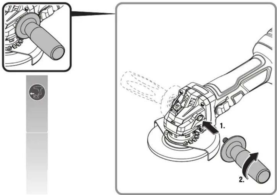
Always work with the auxiliary handle. The auxiliary handle ensures reliable guiding of the power tool.
After working gypsum-containing materials: Blow out the ventilation openings of the power tool and the switch element with dry and oil-free compressed air.
Otherwise, gypsum-containing dust can settle in the power tool housing and switch element, which can harden in connection with humidity. This can impair the switching mechanism.
Use and handling of the battery (battery pack). These safety warnings apply only for 18V FEIN AMP-Share Li-ion batteries.
Use the battery only in AMPShare partner products. 18V batteries marked with AMPShare are fully compatible with the following products:
- All products of the FEIN-18V-AMPShare system - All 18V products from AMPShare partners.
en
35
When working with and charging incorrect, damaged, repaired or reconditioned batteries, imitations or other brands, there is danger of fire and/or explosion.
Observe the battery recommendations in the operating instructions for your product. Only in this way can the battery and the product be operated safely, and the batteries are protected from dangerous overload.
Only charge the batteries with chargers recommended by FEIN or one of the AMPShare partners. A charger that is suitable one type of battery pack may create a risk of fire when used with another battery pack.
The battery is supplied partially charged. To ensure full battery capacity, completely charge the battery in the battery charger before using for the first time.
Store batteries out of the reach of children.
Batteries must not be disassembled, opened or reduced in size. Do not subject batteries to mechanical impact or shock. Hazardous vapours and fluid can escape in case of damage and improper use of the battery. The vapours can irritate the respiratory system. Liquid ejected from the battery may cause skin irritations or burns.
In case of skin contact with battery fluid, rinse immediately with plenty of water. In case of eye contact with battery fluid, wash out the eye with clean water and immediately seek a doctor for treatment!
When the battery fluid has come into contact with objects close by, check the respective components. Avoid skin contact by wearing protective gloves. Clean the parts with dry household paper or replace the parts if necessary. Escaping vapours can irritate the respiratory system. Liquid ejected from the battery may cause skin irritations or burns.
Do not short-circuit the battery. Keep the battery not being used away from paper clips, coins, keys, nails, screws or other small metal objects, that can make a connection from one terminal to another. Shorting the battery terminals together may cause burns or a fire.
The battery can be damaged by sharp objects such as nails or screwdrivers or by external force. An internal short-circuit may occur and the battery can burn, smoke, explode or overheat.
Never maintain damaged batteries. Any maintenance of batteries should be performed only by the manufacturer or by authorised after-sales service centers.

Protect the battery against heat, e.g., against continuous intense sunlight, fire, debris, water, and moisture. Danger of explosion and short-circuiting.
Operate and store the battery only at ambient temperatures between -20 °C and +50 °C. As an example, do not leave the battery in a vehicle in summer. At temperatures < 0 °C, machine-specific performance restrictions are possible.
Charge the battery only at ambient temperatures between 0 °C and +35 °C. Charge the battery via USB connection only at ambient temperatures between +10 °C and +35 °C. Charging the battery outside the temperature range may damage the battery or increase the risk of fire.
Handle discharged batteries with care. Batteries are a source of danger, as they can cause a very high short-circuit current. Even when Li-ion batteries appear to be in a discharged state, they never fully discharge.
Do not immerse the battery in liquids, such as (salt) water or beverages. Contact with liquids can damage the battery. This may result in heat build-up, smoke generation, ignition or explosion of the battery. Do not continue to use the battery and contact an after-sales service authorized by FEIN.
Do not use a damaged battery. The use of a battery must be stopped immediately as soon as abnormal properties, such as odour development, heat, discolouration or deformation occur. Continued operation can cause the battery to generate heat and smoke, ignite or explode.
Do not open, crush, overheat or set fire to the battery. Non-observance of this warning may result in burns and fire. Follow the manufacturer's instructions.
Extinguish burning Li-ion batteries with water, sand or a fire blanket.
Avoid physical blows/impact. Impact and penetration of objects can damage batteries. This may result in leakage, heat build-up, smoke generation, ignition or explosion of the battery.
Never charge the battery unattended overnight. Fire and explosion hazards can result in case of non-observance.
Do not remove the battery from its original packaging until it is going to be used.
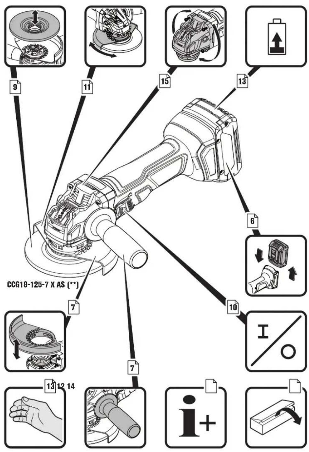
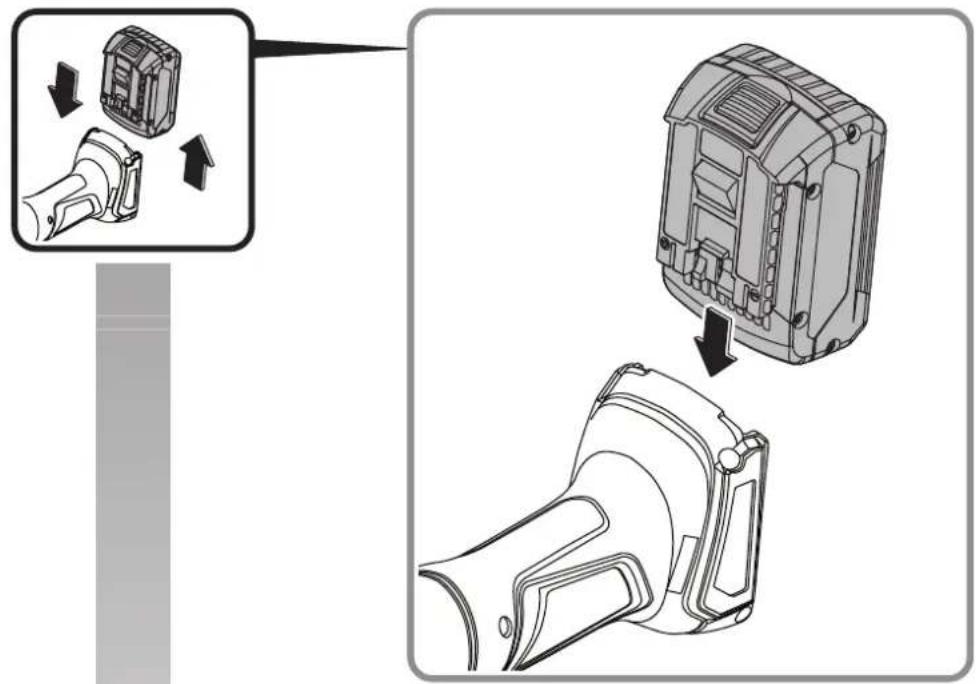
Remove the battery only when the power tool is switched off.
Before any work on the machine itself, remove the battery from the power tool. If the power tool accidentally starts, there is danger of injury.
Protect the battery against moisture and water. Clean contaminated battery terminals and power tool connections with a dry, clean cloth.
Remove the battery when transporting and storing the power tool.
Observe the safety instructions in the manuals of the chargers from FEIN or the AMPShare partners.
Vibration and noise emission values
The vibration and noise emission values given in these instructions have been measured according to a measurement method standardised in EN 62841 and can be used to compare power tools with each other. They are also suitable for a preliminary assessment of vibration and noise exposure.
The given vibration and noise emission values represent the main applications of the power tool.
However, if the power tool is used for other applications, with deviating application tools or insufficient maintenance, the overall vibration values and the noise emission values may differ. This can significantly increase the vibration and noise exposure over the total working period.
en
For an accurate estimation of vibration and noise exposure, the durations when the equipment is switched off or running but not actually in use should also be taken into account. This may significantly reduce the vibration and noise exposure over the total working period.
Identify additional safety measures to protect the operator from the effects of vibration and noise such as: Maintain the power tool and the accessories, keep the hands warm, organization of work patterns.
Handling hazardous dusts
For work procedures with this power tool where material is removed, dusts develop that can be hazardous to one's health.
Contact with or inhaling some dust types, e. g. asbestos and asbestos-containing materials, lead-containing coatings, metal, some wood types, minerals, silicate particles from materials containing stone, paint solvents, wood preservatives, antifouling paints for vessels, can trigger allergic reactions to the operator or bystanders and/or lead to respiratory infections, cancer, birth defects or other reproductive harm. The risk from inhaling dusts depends on the exposition. Use dust extraction matched appropriately for the developing dust, as well as personal protective equipment and provide for good ventilation of the workplace. Leave the processing of asbestos-containing materials to specialists.
Wood and light-metal dust, hot mixtures of grinding dust and chemical materials can self-ignite under unfavourable conditions or cause an explosion. Avoid sparking in the direction of the dust collector as well as overheating of the power tool and the materials being sanded, empty the dust collector/container in time, observe the material manufacturer's working instructions, as well as the relevant regulations in your country for the materials being worked.
Operating Instructions.
Do not use the power tool with a cut-off stand. After heavily straining the power tool, continue to run it at no-load for several minutes in order to cool the application tool down.
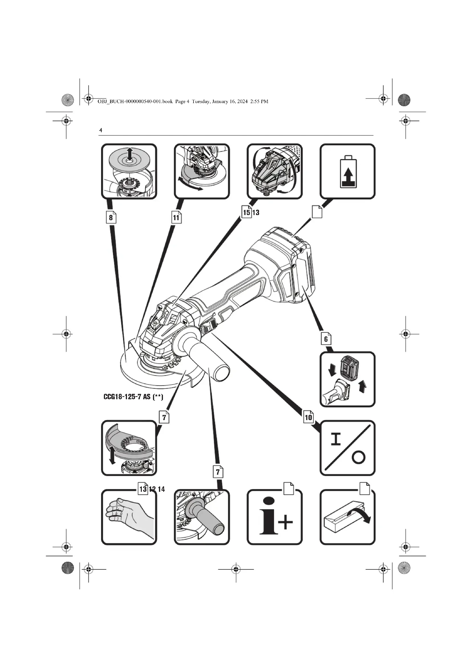
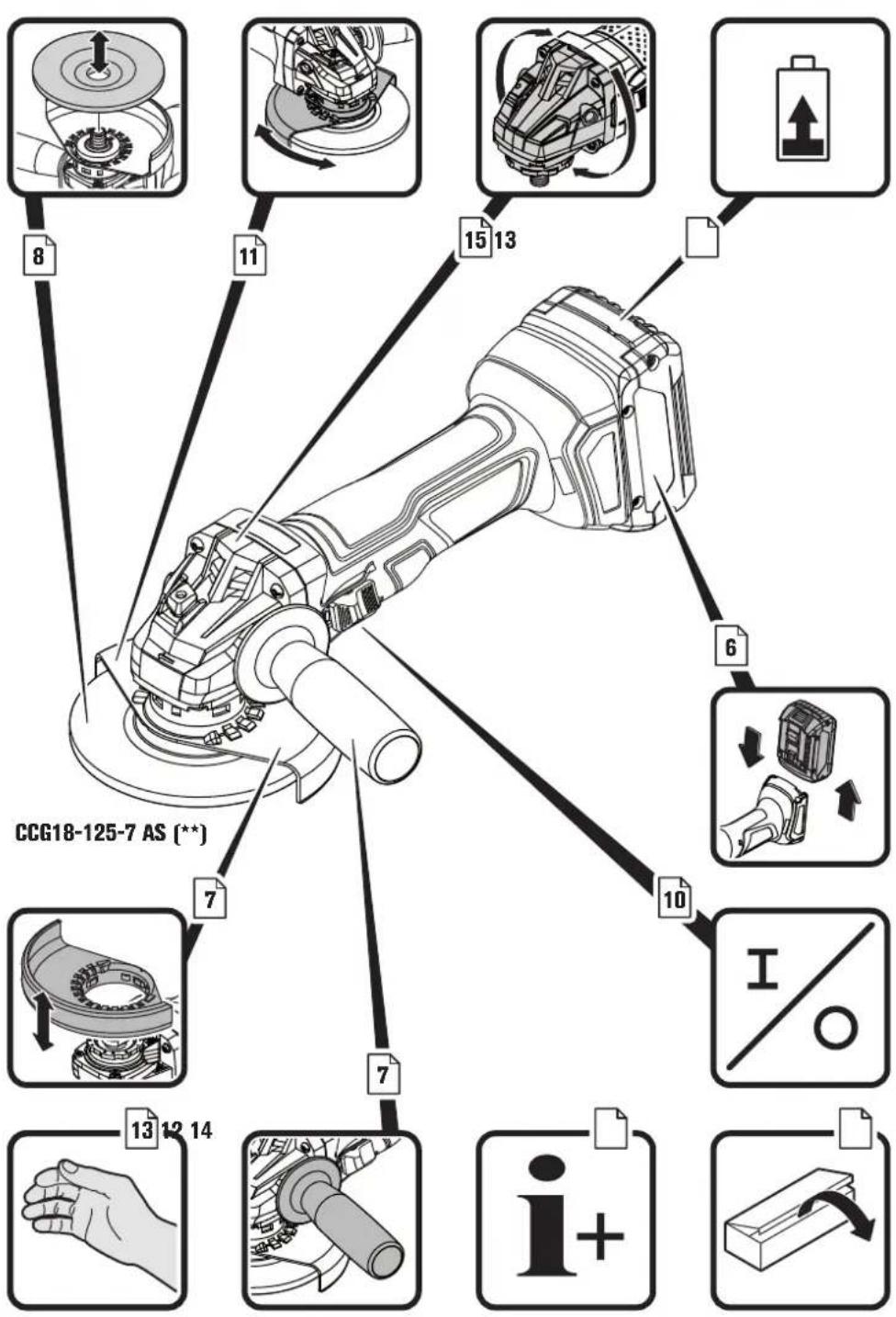
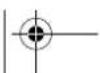
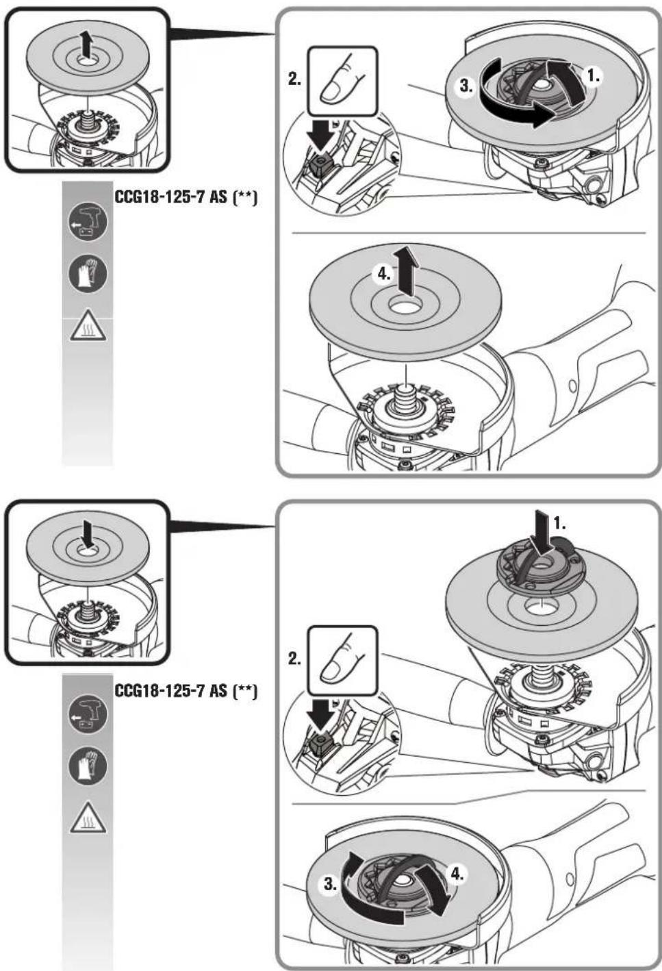
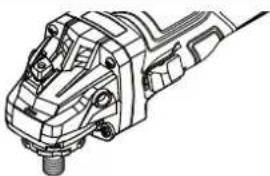
Mounting/dismounting the application tool CCG18-125-7 AS ( ** ):
Press the locking button only when the motor is stopped (see page 8). Otherwise the power tool may be damaged.
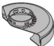
An O-ring is fitted around the centring collar of clamping flange. If this is missing or damaged, it is essential that the O-ring is replaced before further use.
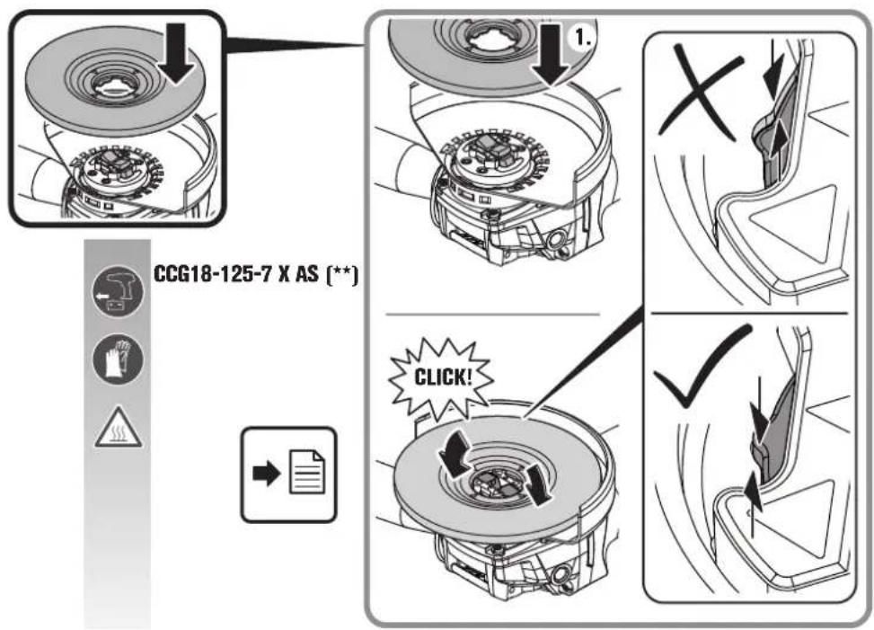
Mounting/dismounting the application tool CCG18-125-7 X AS (\*\*) :
Only use original X-LOCK insert tools that are labelled with the X-LOCK logo. Only original X-LOCK application tools ensure that the clamping thickness of max. 1.6 mm is maintained. A higher clamping thickness can lead to insecure clamping, which can cause the application tool to become loose.
Ensure that the application tool and the holder are not deformed and are free of debris and particles.
Observe the dimensions of the grinding tools. Ensure that both X-LOCK latch noses are open before mounting the X-LOCK application tool. If necessary, clean the area between the two X-LOCK latch noses.
After mounting, check that the edge of the grinding accessory is not higher than the reference surface and thus correctly mounted. If the edge is higher, the mount must be cleaned or the grinding accessory may not be used.
Press the lever (see page 9) only when the motor is stopped.
Do not switch the power tool on with the clamping lever open. Otherwise there is a risk of crushing the hand and fingers.
Do not reach into the area of the clamping jaws. Otherwise there is a risk of crushing the fingers.
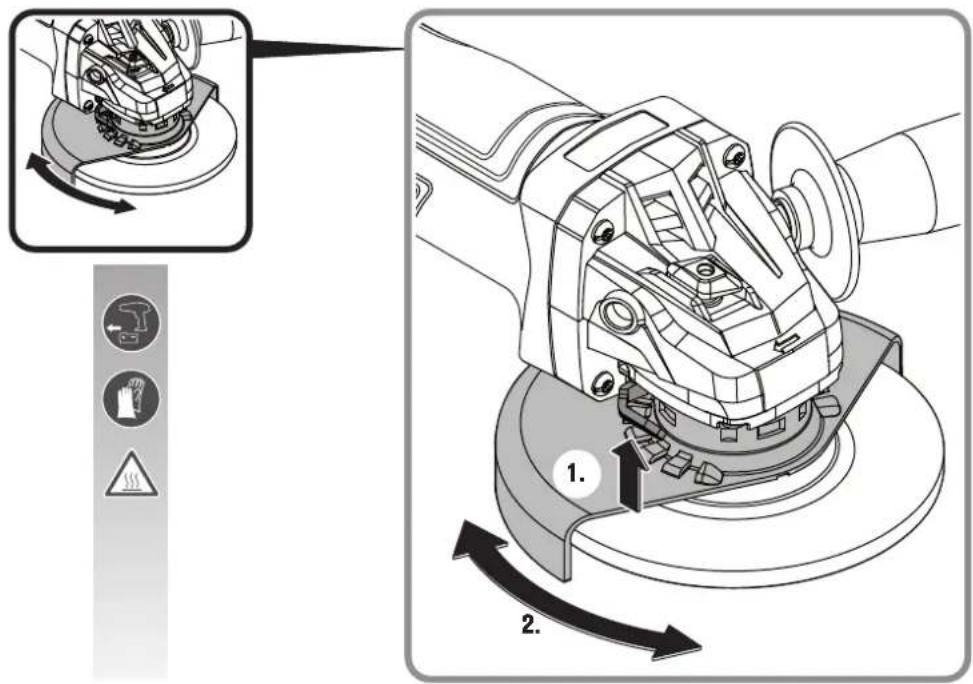
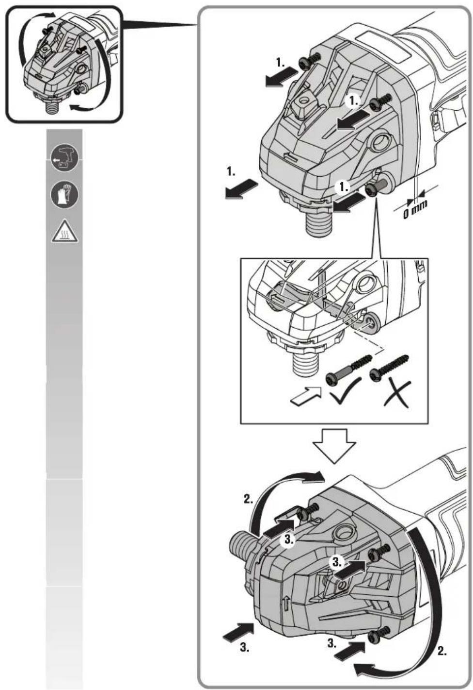
Turning the machine head:
Carefully turn the machine head to the new position (see page 15) without removing it from the housing.
Features
The soft start is used to reduce torque reaction forces when switching on and running up the power tool to the no-load speed.
The restarting protection prevents the power tool from automatically restarting if the power supply is interrupted during operation. In this case, switch off the power tool, check the power supply and then switch the power tool on again.
The electronic overload protection reduces the risk of motor damage if the power tool is overloaded. In this case, the power tool switches off automatically. Afterwards, set the switch to the off position, remove the power tool from the workpiece and check the application tool for damage. Then, switch the power tool on again.
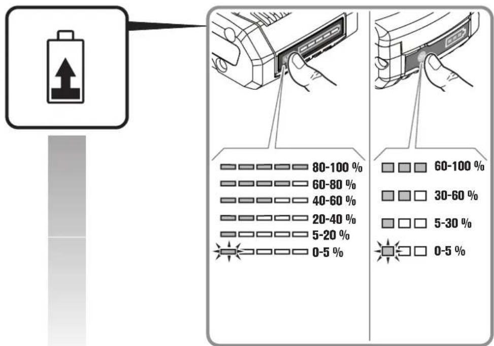
Charge-control Indicator on the Battery (see page 13).
The charge condition can be indicated by the green LEDs of the charge-control indicator on the battery. Press the charge-control indicator button or to indicate the charge condition.
When no LED lights up after pressing the charge-control indicator button, the battery is defective and must be replaced.
Transport.
The recommended Li-ion batteries are subject to the Dangerous Goods Legislation requirements. The user can transport the batteries by road without further requirements.
When being transported by third parties (e.g.: air transport or forwarding agency), special requirements on packaging and labelling must be observed. For preparation of the item being shipped, consulting an expert for hazardous material is required.
Dispatch batteries only when the housing is undamaged. Tape or mask off open contacts and pack up the battery in such a manner that it cannot move around in the packaging. Please also observe possibly more detailed national regulations.


Repair and customer service.
Please observe that power tools may only be repaired, maintained and inspected by qualified electricians, as improper maintenance can result in considerable hazards for the user.
When working metal under extreme operating conditions, it is possible for conductive
dust to settle in the interior of the power tool. Blow out the interior of the power tool via the ventilation slots frequently with dry and oil-free compressed air.
When working materials containing gypsum, dust may occur. This dust can settle inside the power tool as well as on switching elements and harden in combination with humidity. As a result, the switching mechanism may be impaired.
Blow out the interior of the power tool frequently through the ventilation openings and switching elements using dry, oil-free compressed air.
Products that have come into contact with asbestos may not be sent in for repair. Dispose of products contaminated with asbestos according to the applicable country-specific regulations for such disposal.
For FEIN power tools and accessories in need of repair, please contact your FEIN after-sales service. The address can be found on the Internet under www.fein.com.
Renew stickers and warning indications on the power tool when aged and worn.
The current spares parts list for this power tool can be found on our website at www.fein.com.
Use only original spare parts.
If required, you can change the following parts yourself:
Application tools, clamping flanges (where applicable), wheel guard, battery, auxiliary handle, dust-protection filter, hand protection
Maintenance and cleaning.
Occasionally clean the ventilation slots and the battery terminals with a soft, clean and dry brush.
- Do not use chemical substances for cleaning the battery.
Warranty and liability.
The warranty for the product is valid In accordance with the legal regulations in the country where it is marketed. In addition, FEIN also provides a guarantee in accordance with the FEIN manufacturer's warranty declaration.
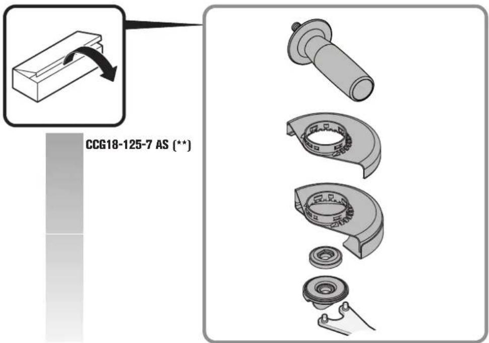
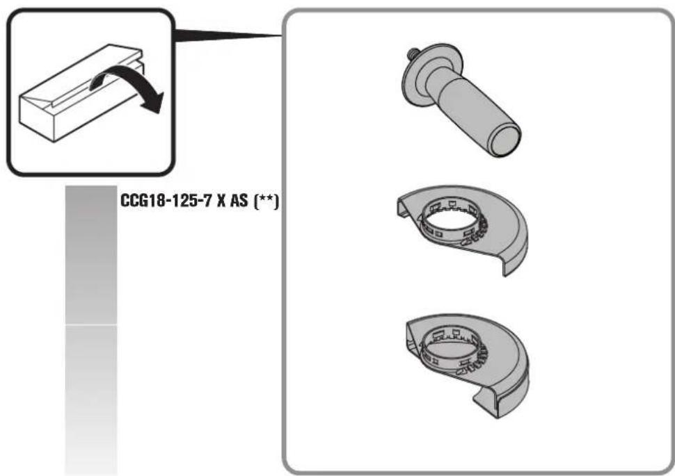
The delivery scope of your power tool may include only a part of the accessories described or shown in this Instruction Manual.
Declaration of conformity.
This CE declaration is only valid for European Union and EFTA (European Free Trade Association) countries and only for products intended for the EU or EFTA market. After placing the product on the EU market the UKCA mark loses its mark validity.
The UKCA declaration is only valid for the Great Britain market (England, Wales and Scotland) and only for products intended for the Great Britain market. After placing the product on the Great Britain market the CE mark loses its mark validity.
Environmental protection, disposal.
Do not dispose of the batteries into household-waste!
Packaging, worn out power tools and accessories should be sorted for environmental-friendly recycling. Dispose of batteries only when discharged.
For batteries that are not completely discharged, insulate the terminals with tape as a protective measure against short-circuiting.
Only for EC countries:
According to the European Guideline 2002/66/EC, defective or used battery packs/batteries, must be collected separately and disposed of in an environmentally-correct manner.
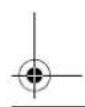
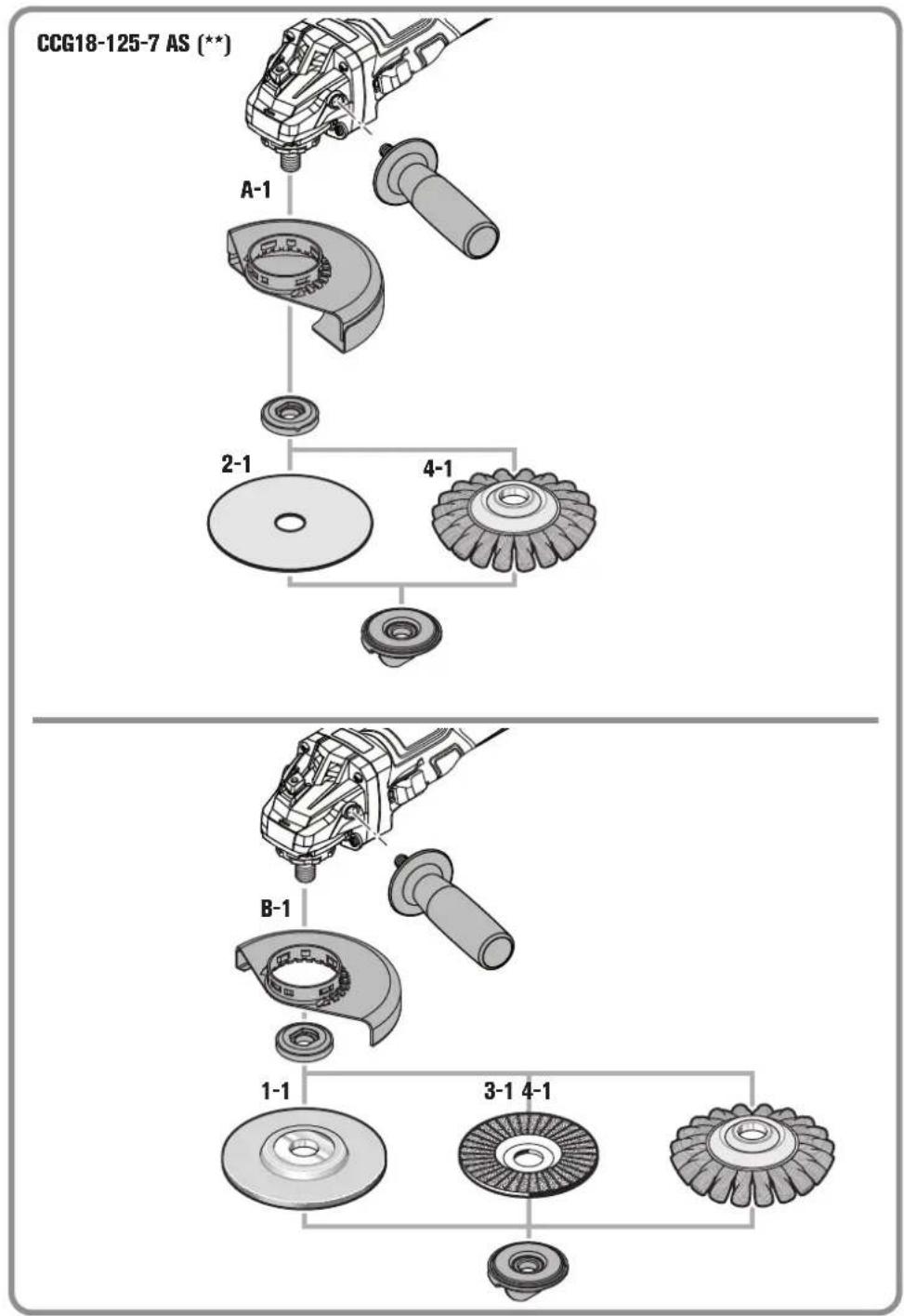
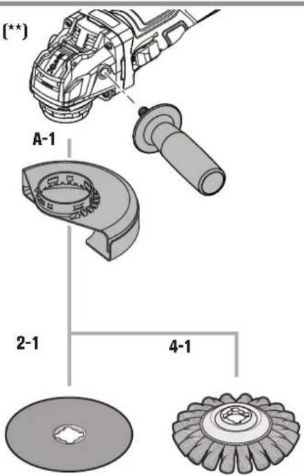
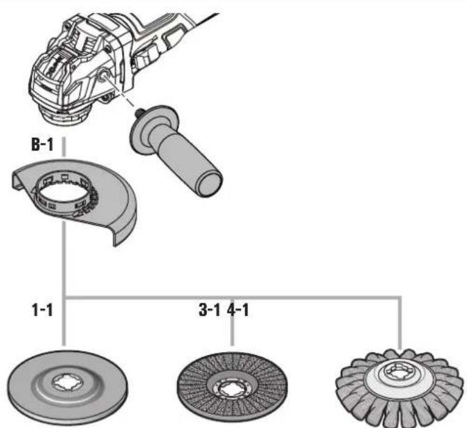
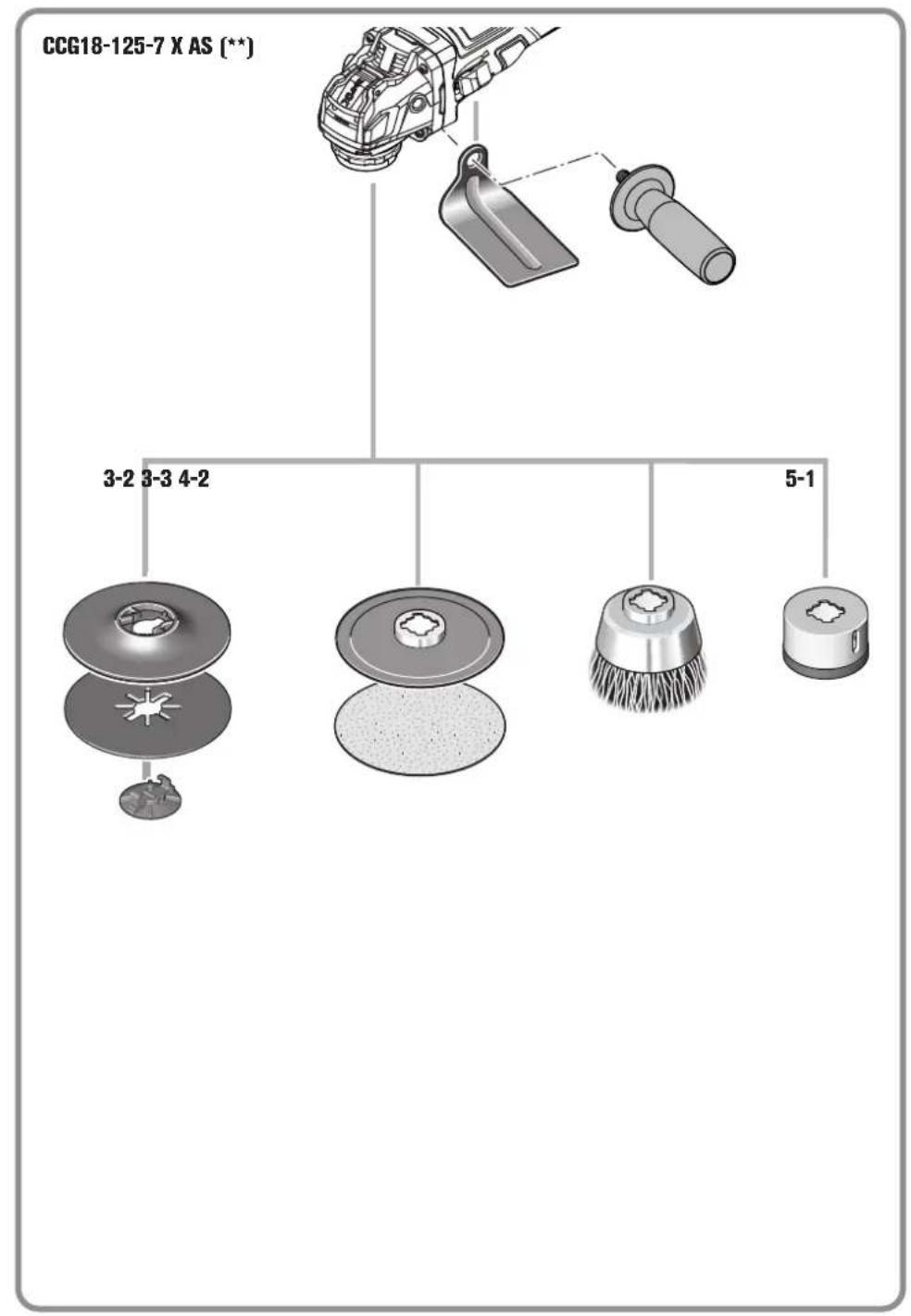
Selection of accessories
(see pages 16 - 20).
Use only original FEIN accessories. The accessories must be intended for the power tool type.
A-1 Wheel guard for cutting, type A
B-1 Wheel guard for grinding, type B
1-1 Grinding disc, type 27
2-1 Cutting disc
(use only with cut-off wheel guard, Type A)
3-1 Flap discs
3-2 Backing pad for fibre sanding sheets, fibre sanding sheets
(mount only with the provided backing-pad clamping unit)
3-3 Backing pad with Velcro, Velcro sanding sheets, sanding fleece with Velcro attachment, sponges (Only CCG18-125-7 AS (**) : Use a fitting open-end spanner)
4-1 Steel tapered twist brush
4-2 Steel-wire cup brush, flap discs
(Only CCG18-125-7 AS (**) : Use a fitting open-end spanner)
5-1 Diamond hole cutter
(Only CCG18-125-7 AS (**) : Use a fitting open-end spanner)

natural_image
Pure geometric diagram with crosshair and circular shapes, no text or symbols presentnatural_image
Pure geometric diagram with crosshair and circular shapes, no text or symbols present106
no
China RoHS Status Certificate
中国 RoHS 认证概况
Table of Toxic and Hazardous Substances/Elements and their Content
as required by China's Management Methods for Controlling Pollution by Electronic Information Products
有毒有害物质 / 成分及其含量表


- en
- For your safety.
- WARNING
- Save all warnings and instructions for future reference.
- Intended use of the power tool:
- Safety warnings common for grinding, sanding, wire brushing or cutting-off operations
- Kickback and related warnings
- Handling hazardous dusts
- Operating Instructions.
- Mounting/dismounting the application tool CCG18-125-7 AS ( ** ):
- Mounting/dismounting the application tool CCG18-125-7 X AS (\*\*) :
- Turning the machine head:
- Features
- Charge-control Indicator on the Battery (see page 13).
- Transport.
- Repair and customer service.
- Maintenance and cleaning.
- Warranty and liability.
- Declaration of conformity.
- Environmental protection, disposal.
- Selection of accessories
- (see pages 16 - 20).
- no
- China RoHS Status Certificate
- 中国 RoHS 认证概况
Brand : Fein
Model : CCG 18-125-7 AS
Category : Grinder