ASP 4 N2 - Log splitter ATIKA - Free user manual and instructions
Find the device manual for free ASP 4 N2 ATIKA in PDF.
User questions about ASP 4 N2 ATIKA
0 question about this device. Answer the ones you know or ask your own.
Ask a new question about this device
Download the instructions for your Log splitter in PDF format for free! Find your manual ASP 4 N2 - ATIKA and take your electronic device back in hand. On this page are published all the documents necessary for the use of your device. ASP 4 N2 by ATIKA.
USER MANUAL ASP 4 N2 ATIKA
natural_image
Icon of a person using a laptop inside a circle (no text or symbols)Originalbetriebsanleitung Original instructions Notice originale Ръководство за експлоатация Originální návod k použití Original brugsanvisning Manual original Alkuperäiset ohjeet Erediti használati utalítás Originalne upute za rad Istruzioni originali
D
Seite 2
GB
Page 11
F
Page 20
BG
Стр. 29
CZ
Str 39
DK
Side 48
E
FIN
Side 66
H
oldal 75
HR
I
NL
Blz. 102
PL
RO
s
SK
SLO
Página 57
Strana 84
Pagina 93
Stronie 111
Pagina 120
Sidan 129
Strana 138
Stran 147
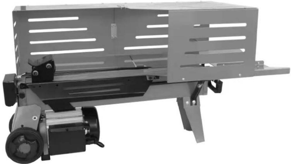
ASP 4 N-2 ASP 5 N-2
natural_image
Exterior view of a mechanical device with a cylindrical base and motor, no visible text or symbols

Hydraulikplan

flowchart
graph TD
    A["Hydraulic Valve"] --> B["Pump"]
    B --> C["Directional Control Valve"]
    C --> D["Motor M"]
    D --> E["Return Line"]
    F["Pressure Sensor"] --> G["Reservoir"]
    H["Actuator"] --> I["Valve"]
    J["Feedback Loop"] --> K["Valve"]
    L["Ground"] --> M["Return Line"]

Do not operate machine before having read the operating instructions, understood all the notes and assembly the machine as described here.
Keep the instructions in a safe place for future use.
Contents
| Extent of delivery 11 | |
| Symbols machine / operating instructions 11/12 | |
| Normal intended use 12 | |
| Residual risks 12 | |
| Safety instructions 12 | |
| Description of device / spare parts 14 | |
| Assembly | 15 |
| Location | 15 |
| Commissioning | 15 |
| Working with the log splitter 15 | |
| Maintenance and care 16 | |
| Transport instructions 17 | |
| Storage | 17 |
| Guarantee | 17 |
| Possible faults 18 | |
| Technical data 19 | |
| Wiring diagram 19 | |
| Hydraulic diagram 19 | |
| EC Declaration of Conformity 156 | |
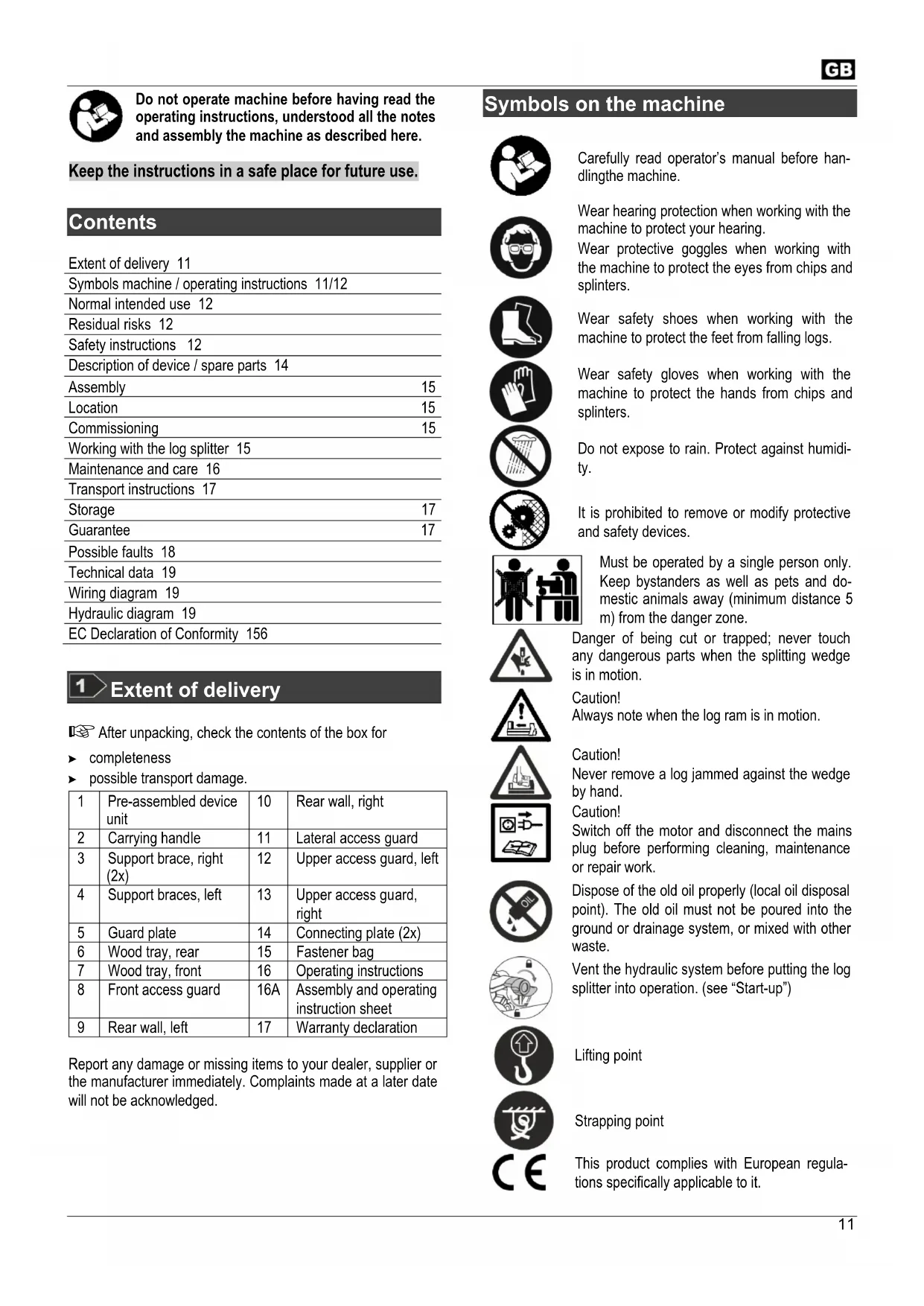
1 Extent of delivery
After unpacking, check the contents of the box for
▶ completeness
▶ possible transport damage.
| 1 | Pre-assembled device unit | 10 | Rear wall, right |
| 2 | Carrying handle | 11 | Lateral access guard |
| 3 | Support brace, right (2x) | 12 | Upper access guard, left |
| 4 | Support braces, left | 13 | Upper access guard, right |
| 5 | Guard plate | 14 | Connecting plate (2x) |
| 6 | Wood tray, rear | 15 | Fastener bag |
| 7 | Wood tray, front | 16 | Operating instructions |
| 8 | Front access guard | 16A | Assembly and operating instruction sheet |
| 9 | Rear wall, left | 17 | Warranty declaration |
Report any damage or missing items to your dealer, supplier or the manufacturer immediately. Complaints made at a later date will not be acknowledged.
Symbols on the machine

Carefully read operator's manual before handling the machine.

Wear hearing protection when working with the machine to protect your hearing.
Wear protective goggles when working with the machine to protect the eyes from chips and splinters.

Wear safety shoes when working with the machine to protect the feet from falling logs.

Wear safety gloves when working with the machine to protect the hands from chips and splinters.

Do not expose to rain. Protect against humidity.

It is prohibited to remove or modify protective and safety devices.

Must be operated by a single person only. Keep bystanders as well as pets and domestic animals away (minimum distance 5 m) from the danger zone.

Danger of being cut or trapped; never touch any dangerous parts when the splitting wedge is in motion.

Caution!
Always note when the log ram is in motion.

Caution!
Never remove a log jammed against the wedge by hand.
Caution!
Switch off the motor and disconnect the mains plug before performing cleaning, maintenance or repair work.

Dispose of the old oil properly (local oil disposal point). The old oil must not be poured into the ground or drainage system, or mixed with other waste.

Vent the hydraulic system before putting the log splitter into operation. (see "Start-up")

Lifting point

Strapping point

This product complies with European regulations specifically applicable to it.
GB
Electrical devices do not go into the domestic rubbish.
Give devices, accessories and packaging to an ecofriendly recycling.
According to the European Directive 2012/19/EU on electrical and electronic scrap, electrical devices that are no longer serviceable must be separately collected and brought to a facility for an environmentally compatible recycling.
Symbols operating instructions

Potential hazard or hazardous situation. Failure to observe these instructions may lead to injuries or cause damage to property.

Important information on proper handling. Failure to observe these instructions may lead to malfunction.

User information. This information helps you to use all the functions optimally.

Assembly, operation and servicing. Here you are explained exactly what to do.

Please refer to the attached assembly and operating instruction sheet for references to figure numbers in the text.

Normal intended use
■ The log splitter must only be used for splitting logs.
- The log splitter is only applicable for the private utilization in the field of house and hobby.
- Only straight-cut logs are suitable for use with the log splitter.
■ Metal parts (nails, wire etc.) must be removed from logs before splitting.
- The intended usage also includes compliance with the operating, servicing and repair conditions prescribed by the manufacturer and following the safety instructions included in the instructions.
- The relevant accident prevention regulations for the operation as well as the other generally acknowledged occupational medicine and safety rules must be complied with.
- Every other form of use is considered improper use. The manufacturer accepts no liability for any damages resulting from improper use, and any risk is in this case borne solely by the user.
- Unauthorised modifications on the log splitter exclude a liability of the manufacturer for damages of any kind resulting from it.
- Only persons who are familiarised with the device and informed about possible risks are allowed to prepare, operate and service this device. Repair works may only be carried out by us or by a customer service agent nominated by us.
Residual risks
Even if used properly, residual risks can exist even if the relevant safety regulations are complied with due to the design determined by the intended purpose.
Residual risks can be minimised if the "Safety advices" and the "Intended usage" as well as the whole of the operating instructions are observed.
Observing these instructions, and taking proper care, will reduce the risk of personal injury or damage to the equipment.
■ Risk of injury from ejected wood pieces.
■ Risk of injury to feet from wood dropping down
- Risk of injury to fingers when detaching jammed wood pieces
- Noncompliance with safety instructions may result in injuries of the operator or property damages.
- Carelessness, failure to comply with the safety regulations and incorrect use can result in injuries to your hands and fingers when the splitting blade is moving.
- Risk from electricity when using improper electrical connections.
■ Touching live parts of opened electrical components.
■ Risk of fire and slipping by leaking hydraulic fluid.
- Impairment of hearing when working on the machine for longer periods of time without ear protection.
In addition, in spite of all the precautionary measures taken, non-obvious residual risks can still exist.
Safety instructions
Before starting this device, read and keep to the following advice. Also observe the preventive regulations of your professional association and the safety provisions applicable in the respective country, in order to protect yourself and others from possible injury.
Pass the safety instructions on to all persons who work with the machine.
Keep these safety instructions in a safe place.
- Persons who work with the firewood splitter must have received proper instructions about the intended work and be familiar with the use of the firewood splitter and the safety instructions.
- Make yourself familiar with the equipment before using it, by reading and understanding the operating instructions.
- Do not use the machine for unsuitable purposes (see "Normal intended use" and "Working with the log splitter").
- Be attentive. Be observant. Attend to what you do. Start working with rationality. Do not use the device when you are tired or under the influence of drugs, alcohol or medications. One moment of carelessness when using the device can result in serious injuries.
- Children and young persons under 18 years of age as well as persons who have not read the instruction manual are not allowed to operate this product.
- Never work while persons, in particular small children, or pets are close to you.
- Do not allow other persons, especially children, to touch the tool or motor.
Personal protective equipment
- Never work without suited protective equipment.
- Do not wear loose-fitting clothes or jewellery, they could be caught by movable parts.
– Hairnet in case of long hair - Eye and ear protection
– Solid shoes with toe protection caps (safety shoes) - Long pants
- Protective gloves
- First-aid material
- Mobile telephone if required
Safety instructions – before working
Carry out the following checks before the initiation and regularly during the working process. Observe the relevant sections in the operating instruction manual:
- Is the device assembled completely and properly?
• Is the device in good and safe condition? - Are the handles clean and dry?
-
Before starting your work make sure that:
-
no other persons, children or animals stay within the working area,
-
you can always step back without any barriers,
— you have always a secure standing position. -
Is workplace free of risks to stumble? Keep your workplace in an orderly condition! Untidiness can result in accidents - Risk of stumbling!
• Take environmental influences into consideration:
- Do not work under insufficient light conditions (e.g. fog, rain, snow flurry or twilight).
- Do not work in bad weather conditions (e.g. risk of lightning, rain, snow flurry).
- Do not use this machine near inflammable liquids or gases.
- The operator is responsible for accidents or risks which occur to other persons or their properties.
- Ensure that you have stand in a secure standing position and maintain your balance at all times.
- Do not modify the machine or parts of it.
Safety instructions – operating
- Assume a working position in the area of the operating handle. Never stand in the splitting wedge's zone.
- Never stand on top of the machine.
- Turn off the device when taking a break so that nobody is at risk. Secure the device against unauthorized access.
Safety notices for firewood splitters
- The log splitter may only be operated by a single person.
- Never try to split logs containing nails, wire or other similar objects.
- Already split wood and wood chips create a dangerous working area. The operator may stumble, slip or fall. Always keep the working area neat and tidy.
- Never place the hands on or near any moving parts of the machine when it is switched on. Maintain a safe distance from the log, the ram and the wedge in order to protect your hands from injury.
- Only split wood that corresponds to the dimensions to be processed.
Safety instructions – while working
- Never work alone. Keep acoustic and visual contact to other persons at all times to allow immediate first aid in emergency cases.
- Immediately stop the engine at imminent danger or in emergency cases.
- Never leave the device running unattended.
- Immediately stop working when you feel unwell (e.g. headache, dizziness, nausea, etc.). Otherwise there is an increased risk of accidents.
- Do not overload the machine! You work better and safer in the given performance range.
- Take breaks when working so that the engine can cool down.
Behaviour in an emergency situation
- Initiate all required first aid measures suited for the injury and seek qualified medical advice as quick as possible.
- Protect the injured person against further injuries and immobilise the injured person.
General safety instructions
- Use the machine, accessories, tools etc. in compliance with these instructions. When doing so take the work conditions and the activity to be carried out into account. The use of the machine for other than the intended applications may cause dangerous situations.
- Do not spray machine with water (this is hazardous due to live components).
- Do not leave the machine standing in the rain or use when raining.
- Maintain the machine carefully:
– Follow the maintenance instructions. - Keep handles dry and free of oil, resin and grease.
- Check the machine for possible damage:
- Before further use of the machine the safety devices must be checked carefully for their proper and intended function. Only operate the device with complete and correctly attached safety equipment and do not alter anything on the device that could impair its safety.
GB
- Check whether movable parts function perfectly and do not stick or whether parts are damaged. All parts must be correctly installed and fulfil all conditions to ensure perfect operation.
-
Damaged safety devices and parts must be properly repaired or exchanged by a recognized, specialist workshop; insofar as nothing else is stated in the instructions for use.
– Damaged or illegible safety labels have to be replaced. -
Do not allow any tool key to be plugged in!
Before switching on, checking always that all tools are removed. - Store unused equipment in a dry, locked place out of the reach of children.
-
Switch the machine off and remove the mains plug from the socket when
-
Carrying out repair work.
- Performing maintenance and cleaning work.
- Eliminating faults.
- Checking of connection cables whether they are swallowed or damaged
- Storage and transport
– Leaving unattended (even during short interruptions).

Do not carry out repair operations on the machine other than those described in section "Maintenance" but contact the manufacturer or authorized customer service centres.

Repairs to other parts of the machine must be carried out by the manufacturer or one of his customer service points.

Use only original spare parts and accessory parts. Accidents can arise for the user through the use of other spare parts. The manufacturer is not liable for any damage or injury resulting from such action.
Electrical safety
- Design of the connection cable according to IEC 60245 (H 07 RN-F) with a core cross-section of at least
2.5 mm^2 for a maximum cable length of up to 10 m - Never use the machine with a power supply cable of over 10 m in length. Longer power supply cables will cause a drop in voltage. The motor will not be able to provide its maximum performance and the operation of the machine will be impaired.
- Plugs and coupler outlets on connection cables must be made of rubber, non-rigid PVC or other thermoplastic material of same mechanical stability or be covered with this material.
- The connector of the connection cable must be splash-proof.
- When installing the power supply cable observe that it does not interfere, is not squeezed, bended and the plug connection does not get wet.
-
Wind off completely the cable when using a cable drum.
-
Do not use the cable for purposes for which it is not meant. Protect the cable against heat, oil and sharp edges. Do not use the cable to pull the plug from the socket.
- Regularly check the extension cables and replace them if they are damaged.
- Do not use any defective connection cables.
- When working outdoors, only use extension cables especially approved and appropriately labelled for outdoor use.
- Do not set up any provisional electrical connections.
- Never bypass protective devices or deactivate them.

The electrical connection or repairs to electrical parts of the machine must be carried out by a certified electrician or one of our customer service points. Local regulations – especially regarding protective measures – must be observed.
1 14
Description of device / Spare parts
→ Please refer to the attached assembly and operating instruction sheet.
| Pos. | Order no. | Designation | |
| ASP 4 N-2 | ASP 5 N-2 | ||
| 1 | × | Preassembled device | |
| 2 | 360348 | Carrying handle | |
| 3 | 359782 | Support brace | |
| 4 | 359783 | Support braces | |
| 5 | 359784 | 359796 | Guard plate |
| 6 359 | 785 359797 | Wood tray, rear | |
| 7 359 | 786 359789 | Wood tray, front | |
| 8 359 | 787 Front access guard | ||
| 9 | 359789 | 359799 | Rear wall, left |
| 10 | 359788 | Rear wall, right | |
| 11 | 359790 Lateral access guard | ||
| 12 | 359792 359800 Upper access guard, left | ||
| 13 | 359791 Upper access guard, right | ||
| 14 | 359793 | Connecting plate | |
| 15 | × | Fastener bag | |
| 16 | × | Operating instructions | |
| 16A | × | Assembly and operating instruction sheet | |
| 17 | × | Warranty declaration | |
| 18 | × | Blade guard | |
| 19 | × | Bleed screw | |
| 20 | 360379 | 360349 | Dipstick |
| 21 | × | Operating pushbutton | |
| 22 | × | Supporting foot | |
| 23 | × | Cable | |
| 24 | × | Motor | |
| 25 | 360354 | Wheel | |
| 26 | × | Operating handle | |
| 27 | × | Log ram | |
| 28 | × | Piston rod | |
| 29 | 360350 | Oil seal | |
| 30 | 359776 | Safety label | |
Assembly

Connect the firewood splitter to the power supply system only after having finished the complete assembly.
Mount the wood trays and the access guard as shown in Figures 2 - 12 on the assembly and operating chart.

Do not tighten the screw connections too firmly at first, the sheet metal parts must still remain movable!

Make sure after mounting that all screws are tightened firmly.
Location

Position the log splitter on a work surface at a height of about 72 - 85 cm, this will create a comfortable working position.

The device must be firmly mounted on a work surface for safe handling.
The small parts required for mounting are not included in the scope of delivery. Use the following for this purpose:
▶ Hexagonal screw M 8 x ....
(Length depending on the thickness of the work table)
▶ Washer ∅ 8mm
▶ Hexagon nut M 8, self-locking
Ensure that the working area meets the following conditions:
– secured against slipping
- even
– free of tripping hazards
- adequate light

Do not operate the machine in the direct vicinity of gas or petrol pipes or containers, or any other easily inflammable materials.
Commissioning
- Check that the machine is completely and correctly assembled.
■ Before each use, check
– Connection cables for defects (cracks, cuts, etc.).

Do not use any defect cables
- there are no damages at the machine (see „safety instructions“)
- All screws are tight.
– check the hydraulic system for any possible leaks - the oil level
Mains connection
- Compare the voltage given on the machine model plate with the mains voltage and connect the machine to the relevant and properly earthed plug.
- Only use extension cables with sufficient core cross-section.
- Connect the machine via a 30 mA fault current safety switch.

Fuse protection: 10 A time-lag


Switching on:

Push the button (21). The motor is running as long as the button remains pushed.

Switching off
Stop pushing the button.

Prior to every use, check the function of the disconion mechanism (by switching on and off).
Do not use any device where the operating pushbutton does not work properly. Repair or replace damaged pushbuttons immediately.
Hydraulics

Check the hydraulic lines and hoses before each use.
- Never operate the machine in the event of any possible danger from hydraulic fluid.
- Ensure that the machine and working area are clean and free of oil.
Danger of slippage or fire! - Check the hydraulic reservoir regularly to ensure that it contains enough hydraulic oil (see “Care and maintenance”).
Capacity: approx. 2.4 litres ASP 4 N-2 approx. 3.5 litres ASP 5 N-2
Working with the log splitter
What type of logs can I split?
Size of logs
| ASP 4 N-2 | ASP 5 N-2 | |
| Wood length: | min. 130 – max. 370 mm | min. 200 – max. 520 mm |
| Diameter: | min. 50 – max. 250 mm | |
The log diameter is a recommended guideline figure, because: — thin logs can be difficult to split if they contain knots or if the fibres are too strong.
Do not try to split green logs. Dry logs are much easier to split, and do not cause jams as often as green (damp) wood.

Hardwood tend to bursting: Exercise utmost caution! Be aware that wood with knots can burst open. Never split wood that has not been debranched beforehand.
Special instructions for splitting logs
Preparations:
The logs to be split should be cut to the maximum dimensions. Ensure also that the logs are cut straight and square.
Place the log properly on the log splitter, so as not to cause any risk of stumbling or falling to the operator.
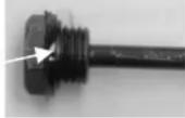
Bleeding
Vent the hydraulic system before putting the log splitter into operation.
- Open the bleed screw (19) 3 – 4 complete turns.
- Close the bleed screw again when you are finished splitting logs.
① If the hydraulic system is not vented, the trapped air will damage the seals and cause permanent damage to the log splitter.

Operating
Two-hand operation
- Press the operating pushbutton (21) on the electric motor. Wait a few moments until the motor has reached its operating revolutions and the required pressure has been built up in the hydraulic pump.
- 17 Press the operating handle (26) down simultaneously. → The log ram (27) pushes the log against the splitting wedge, and the log will be split.
- Release the operating lever as well as the operating pushbutton. The log ram will now return to its original starting position
Splitting logs
- Always place the logs lengthwise and flat on the main frame of the log splitter. The log must be enclosed by the log guide plates.
■ 18 Never place the log on the frame at an angle.
■ Always ensure that the splitting wedge (18) and the log ram (27) contact the ends of the log at right-angles.
■ Never try to split two logs at once. - Never try to remove or replace the log during the splitting process.
① Never try to force the splitting of the log by maintaining the pressure for several seconds. This can lead to damage to the machine.
Reposition the log on the main frame and repeat the splitting process, or put the log to one side.
How to release a jammed log?
-
Loose the operating lever as well as the operating pushbutton that the log ram can go back.
-
20 Place a triangular wooden chock under the log, then move the log ram forward so that it pushes the chock under the jammed log.
- If the log is not released, keep repeating this procedure, using larger chocks, until the log is released.
⚠️ Never use a hammer to release a jammed log, and keep your hands away from the log.
Do not enlist the aid of a second person - this is a one-man job.
22 Do not try to release the log by using a hammer, since this may break the motor block.
Finishing work
➢ Attend to that the log ram has gone back to its basic position.
➢ Then remove the plug from the power socket.
15 Close the bleed screw (19).
➢ Follow the care and maintenance instructions.
Maintenance and care

Remove the plug from the power socket before starting any maintenance or cleaning work.
Maintenance and repair work other than those described in this chapter is only allowed to be carried out by service staff.
For maintaining and cleaning, removed security devices must unconditionally be mounted properly and proved again.
Only use genuine spare parts. Other than genuine parts may result in unpredictable damages and injury.

Wear protective gloves in order to avoid injury to the ds.
i Observe the following in order to keep the log splitter in good working order:
- Clean the machine thoroughly after you have finished using it.
■ Remove any resin remains on the machine.
- Oil the piston rod (28) regularly with an environmentally friendly spray oil.
- Check the oil level and change the oil as necessary.
Sharpening the splitting wedge
① After extended periods of use, or if the splitting performance is reduced, sharpen the splitting wedge (18) with a file (and remove any burrs).
How do I check the oil level?
- The log ram (27) must be in its starting position.
- Stand the log splitter on end, with the filler opening at the top.
A second person will be required to up-end and hold the log splitter. - 23 Unscrew the dipstick (20). Do not drop or lose the oil seal when removing the dipstick.

- Clean the dipstick and the oil seal.
- Replace the dipstick fully into the oil reservoir.
- Now remove the dipstick again, and read off the oil level.
25 The oil level must lie between MIN and MAX.
Replenish the same type of oil if the level is too low (MIN or less).
- Check the oil seal and replace it if it is damaged in any way.
Oil seal (23)
- Replace the dipstick and screw it firmly into place.
Caution! Do not tighten the screw too tightly, since this may damage the oil seal or the thread in the cylinder cover.
When should I change the oil?
The first oil change should be carried out after 50 operating hours, and then every 250 operating hours.

Changing the oil:
- The log ram must be in its starting position.
-
Place a container under the log splitter to catch the old oil. The container should have a capacity of at least 4 litres.
-
23 Unscrew the dipstick. Do not drop or lose the oil seal when removing the dipstick.
-
24 Now tip the machine to empty the oil into the container.
-
Stand the log splitter on end, with the filler opening at the top.

A second person will be required to up-end and hold the log splitter.
-
24 Pour in the new hydraulic oil (Quantity, see "Technical Data") using a clean funnel.
-
Clean the dipstick and the oil seal.
-
Check the oil seal and replace it if it is damaged in any way.
-
Replace the dipstick and screw it firmly into place. Caution! Do not tighten the screw too tightly, since this may damage the oil seal or the thread in the cylinder cover.
Dispose of the old oil properly (local oil disposal point). The old oil must not be poured into the ground or drainage system, or mixed with other waste.
Hydraulic oil
We recommend the following hydraulic oils for the hydraulic cylinder:
Shell Tellus T 22
Aral Vitam Gf 22
▶ BP Energol HLP 22 → order no. 400142 (1 litre)
Mobil DTE 11
or equivalent
Do not use any other types of oil. The use of any other type of oil will adversely affect the operation of the hydraulic cylinder.
Transport instructions
Before each transport

- Switch off device.
- Tighten the vent screw
— Pull out power plug - Remove the split wood
13 To transport, hold the carrying handle and lift the log splitter. In this position, it is easy to move the log splitter.
■ Use the lifting points provide for transport with a crane.
- Secure the device against tipping over or sliding away when transporting it by crane.
■ When transporting the product within a car put it in the boot or on a separate loading area. While doing so, secure the log splitter at the points provided with straps.
Storage

Before each storage
- Switch off device.
- Tighten the vent screw
– Pull out power plug
Store machines that are not in use in a dry locked place protected against frost and outside the reach of children and unauthorized persons.
Before extended storage, please observe the following to increase the service life of the device and to ensure smooth operation:
– Thoroughly clean the device.
– Check the device for damaged or worn parts.
Guarantee
Please observe the enclosed terms of guarantee.
Possible faults
| Problem | Possible Cause | Remedy |
| Logs are not being split properly(insufficient splitting performance) | ⇒ The log is not positioned correctly⇒ The log exceeds the maximum dimensions or the wood is too hard for the performance of the machine⇒ Splitting blade does not split log⇒ Oil leak⇒ Hydraulic pressure too low⇒ Incorrect connecting lead (longer than 10 m or too small cable cross-section). | ⇒ Reposition the log correctly⇒ Cut the log to the required dimensions⇒ Sharpen splitting blade, check for burrs or notches⇒ Place a sheet of cardboard under the log splitter in order to locate the leak. To correct the problem, refer to the manufacturer⇒ Check the oil level and add more oil if necessaryIf the problem cannot be rectified, refer to the manufacturer⇒ Use the correct connecting lead |
| Log ram travels out jerkily or under heavy vibration | ⇒ Air in the circuit | ⇒ Open the bleed screw⇒ Check the oil level and add more oil if necessaryIf the problem cannot be rectified, refer to the manufacturer |
| Log ram will not move out | ⇒ Hydraulic pump defective | ⇒ To correct the problem, refer to the manufacturer |
| Motor does not start | ⇒ No power supply.⇒ Mains cable defective.⇒ Electric motor defective | ⇒ Check the fuse⇒ Replace the connection cable or have it checked by an electrician⇒ To correct the problem, refer to the manufacturer |
| Oil leak at the dipstick | ⇒ Oil seal at the dipstick not sealing | ⇒ Replace the oil seal. |
In case of further faults or inquiries please contact your local dealer.
Technical data
| Type / Model ASP 4 N-2 ASP 5 N-2 | ||
| Year of construction see last page | ||
| Splitting force 40 kN (4 t) 50 kN (5 t) | ||
| Hydraulic pressure 16,5 Mpa (165 bar) 20,6 Mpa (206 bar) | ||
| Log length 130 – 370 mm 200 – 520 mm | ||
| Log diameter 50 – 250 mm 50 – 250 mm | ||
| Stroke 290 mm 370 mm | ||
| Feed speed 3,8 cm/s 3,7 cm/s | ||
| Return speed 6,4 cm/s 6,2 cm/s | ||
| Piston rod diameter | 30 mm | |
| Hydraulic oil (max.) | 2.4 litres 3.5 litres | |
| Electric motor performance | P_1 = 1500 W | P_1 = 2200 W S3 25% |
| Power supply, Short circuit-current | 230 V~ 50 Hz, 1 kA | |
| Sound pressure L_PA (Idling) | 78,8 dB (A) | |
| Sound pressure L_PA (under load) | 89,8 dB (A) | |
| Dimensions | Length 995 x Width 425 x Height 610 mm | Length 1160 x Width 425 x Height 610 mm |
| Weight | 49 kg | 55 kg |
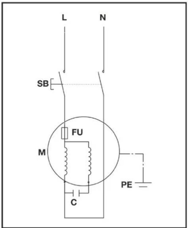
Wiring diagram
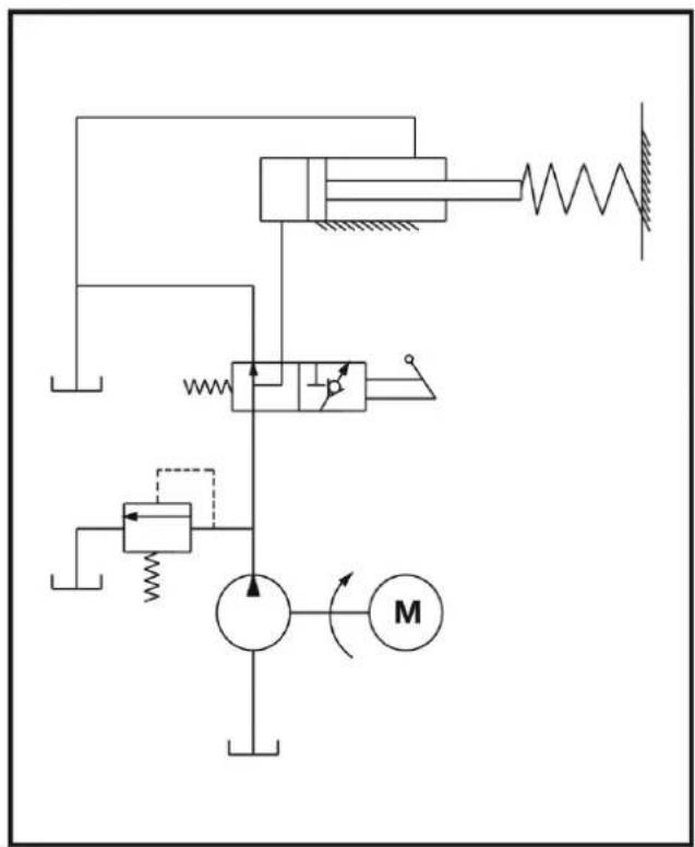
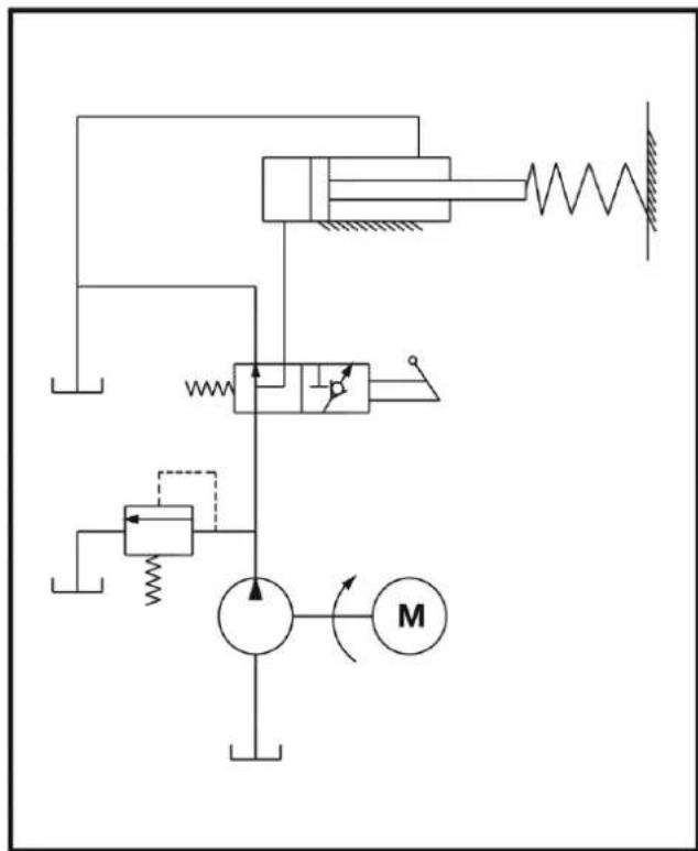
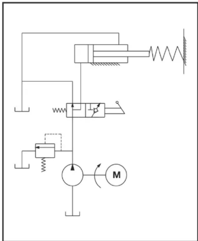
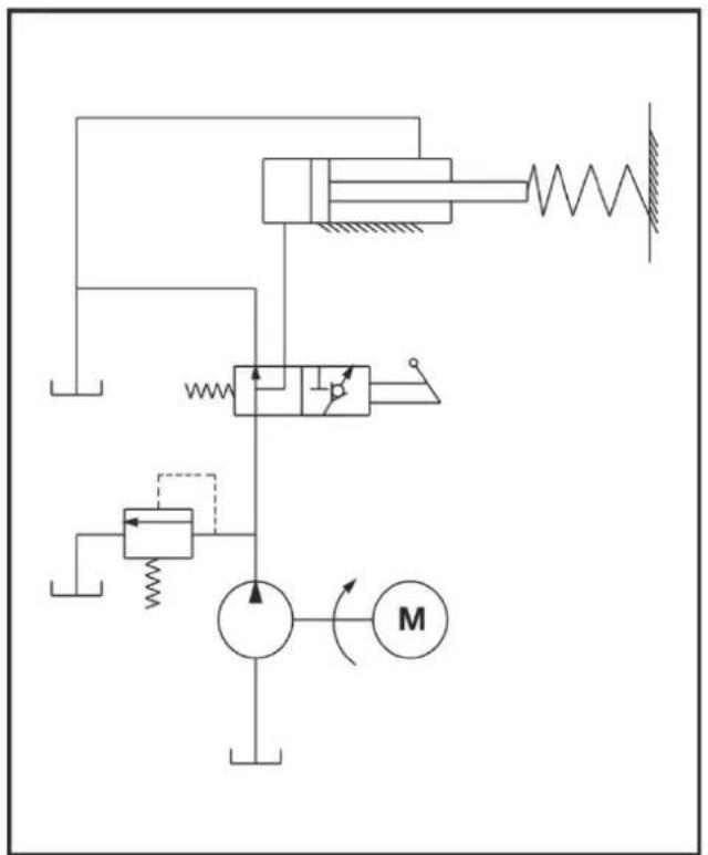
Hydraulic diagram


Schéma hydraulique

flowchart
graph TD
    A["Hydraulic Pump"] --> B["Pump"]
    B --> C{Valve}
    C --> D["Directional Control Valve"]
    D --> E["Motor"]
    E --> F["Return Line"]
    F --> G["Pressure Gauge"]
    G --> H["Reservoir"]
    H --> I["Actuator"]
    I --> J["Feedback Loop"]
    J --> K["Return Line"]
    K --> L["Return Line"]
    L --> M["Return Line"]
    M --> N["Return Line"]
    N --> O["Return Line"]
    O --> P["Return Line"]
    P --> Q["Return Line"]
    Q --> R["Return Line"]
    R --> S["Return Line"]
    S --> T["Return Line"]
    T --> U["Return Line"]
    U --> V["Return Line"]
    V --> W["Return Line"]
    W --> X["Return Line"]
    X --> Y["Return Line"]
    Y --> Z["Return Line"]
Хидравлична схема
flowchart
graph TD
    A["Hydraulic Pump"] --> B["Pump"]
    B --> C{Valve}
    C --> D["Directional Control Valve"]
    D --> E["Motor"]
    E --> F["Return Line"]
    style A fill:#f9f,stroke:#333
    style B fill:#ccf,stroke:#333
    style C fill:#cfc,stroke:#333
    style D fill:#fcc,stroke:#333
    style E fill:#cff,stroke:#333
Schéma hydraulické

flowchart
graph TD
    A["Hydraulic Pump"] --> B["Pump"]
    B --> C{Valve}
    C --> D["Directional Arrow"]
    D --> E["Motor"]
    E --> F["Return Line"]
    F --> G["Actuator"]
    G --> H["Pressure Gauge"]
    H --> I["Reservoir"]
    I --> J["Check Valve"]
    J --> K["Return Line"]
    K --> L["Actuator"]
    L --> M["Reservoir"]
    M --> N["Check Valve"]
    N --> O["Return Line"]

Inden hver transport

Hydraulikplan
flowchart
graph TD
    A["Hydraulic Pump"] --> B["Pump"]
    B --> C{Valve}
    C --> D["Directional Control Valve"]
    D --> E["Motor"]
    E --> F["Return Line"]
    style A fill:#f9f,stroke:#333
    style B fill:#ccf,stroke:#333
    style C fill:#cfc,stroke:#333
    style D fill:#fcc,stroke:#333
    style E fill:#cff,stroke:#333

Plano hidráulico

flowchart
graph TD
    A["Hydraulic Pump"] --> B["Pump"]
    B --> C{Valve}
    C --> D["Directional Control Valve"]
    D --> E["Motor"]
    E --> F["Return Line"]
    style A fill:#f9f,stroke:#333
    style B fill:#ccf,stroke:#333
    style C fill:#cfc,stroke:#333
    style D fill:#fcc,stroke:#333
    style E fill:#cff,stroke:#333
Hydraulikkakaavio

flowchart
graph TD
    A["Hydraulic Pump"] --> B["Pump"]
    B --> C{Valve}
    C --> D["Directional Arrow"]
    D --> E["Motor"]
    E --> F["Return Line"]
    F --> G["Actuator"]
    G --> H["Pressure Gauge"]
    H --> I["Reservoir"]
    I --> J["Check Valve"]
    J --> K["Return Line"]
    K --> L["Actuator"]
    L --> M["Reservoir"]
    M --> N["Check Valve"]
    N --> O["Return Line"]

Shema hidraulike

flowchart
graph TD
    A["Hydraulic Pump"] --> B["Pump"]
    B --> C{Valve}
    C --> D["Directional Control Valve"]
    D --> E["Motor"]
    E --> F["Return Line"]
    F --> G["Pressure Gauge"]
    G --> H["Reservoir"]
    H --> I["Actuator"]
    I --> J["Check Valve"]
    J --> K["Return Line"]
    K --> L["Return Line"]
    L --> M["Return Line"]
    M --> N["Return Line"]
    N --> O["Return Line"]
    O --> P["Return Line"]
    P --> Q["Return Line"]
    Q --> R["Return Line"]
    R --> S["Return Line"]
    S --> T["Return Line"]
    T --> U["Return Line"]
    U --> V["Return Line"]
    V --> W["Return Line"]
    W --> X["Return Line"]
    X --> Y["Return Line"]

Hydraulicaschema
flowchart
graph TD
    A["Hydraulic Pump"] --> B["Pump"]
    B --> C{Valve}
    C --> D["Directional Control Valve"]
    D --> E["Motor"]
    E --> F["Return Line"]
    style A fill:#f9f,stroke:#333
    style B fill:#ccf,stroke:#333
    style C fill:#cfc,stroke:#333
    style D fill:#fcc,stroke:#333
    style E fill:#cff,stroke:#333

Schema hidraulice

Hydraulikschema
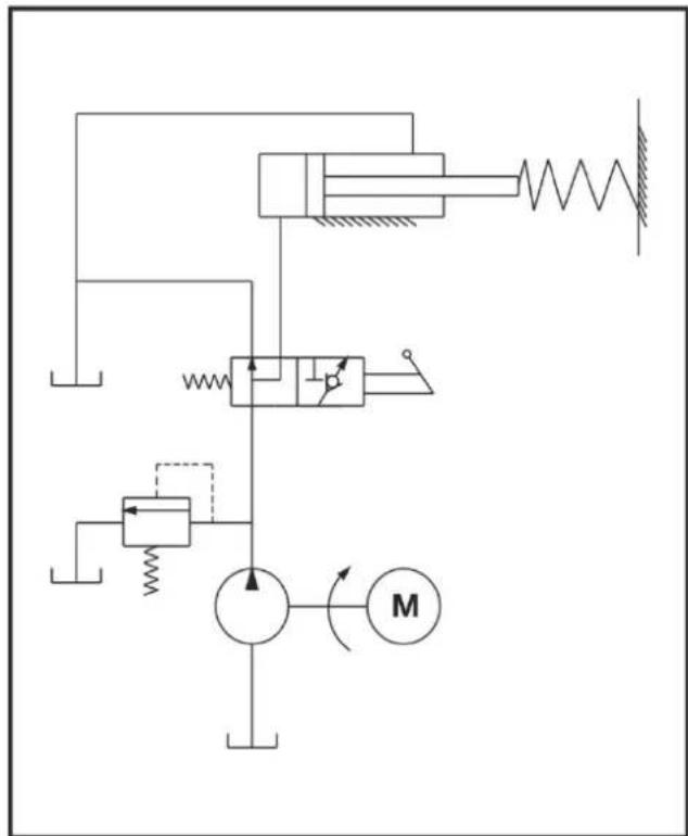

Schéma hydrauliky


Hidravlični načrt

flowchart
graph TD
    A["Hydraulic Pump"] --> B["Pump"]
    B --> C{Valve}
    C --> D["Directional Control Valve"]
    D --> E["Motor"]
    E --> F["Return Line"]
    style A fill:#f9f,stroke:#333
    style B fill:#ccf,stroke:#333
    style C fill:#cfc,stroke:#333
    style D fill:#fcc,stroke:#333
    style E fill:#cff,stroke:#333
Tehnične spremembe pridržane!
GB EC Declaration of Conformity according to Directive: 2006/42/EC
GB We herewith declare
GB under our sole responsibility, that the product
Brennholzspalter (Log splitter) ASP 4 N-2, Serial number: 000001 - 020000
Brennholzspalter (Log splitter) ASP 5 N-2, Serial number: 000001 - 020000
is conform with the above mentioned EC directive as well as with the provisions of the guidelines below: 2014/30/EU, 2011/65/EU
GB Following harmonized standards have been applied: