MKS 4245 - Saw Hurricane - Free user manual and instructions
Find the device manual for free MKS 4245 Hurricane in PDF.

| Product type | Gas chainsaw |
| Brand | Hurricane |
| Model | MKS 4245 |
| Displacement | 42 cm³ |
| Maximum power | 1,7 kW |
| Bar length (guide bar) | 45 cm (18 inches) |
| Cutting length | 40 cm |
| Chain pitch | 10 mm |
| Chain thickness | 1,3 mm |
| Idle speed | 3 100 rpm (±10 %) |
| Maximum speed | 8 000 rpm |
| Fuel tank capacity | 400 ml |
| Oil tank capacity | 220 ml |
| Automatic chain lubrication | Yes |
| Chain brake | Yes |
| Anti-vibration system | Yes |
| Centrifugal clutch | Yes |
| Reduced kickback chain | Yes |
| Net weight (with chain and guide bar) | 6,5 kg |
| Weight without chain or guide bar | 5,6 kg |
| Sound pressure level | 103 dB(A) |
| Sound power level | 114 dB(A) |
| Vibrations (front handle) | 11,34 m/s² |
| Fuel | Unleaded gasoline mixed with 2-stroke oil (40:1) |
| Spark plug gap | 0,6 mm |
| Warranty | 5 years |
Frequently Asked Questions - MKS 4245 Hurricane
User questions about MKS 4245 Hurricane
0 question about this device. Answer the ones you know or ask your own.
Ask a new question about this device
Download the instructions for your Saw in PDF format for free! Find your manual MKS 4245 - Hurricane and take your electronic device back in hand. On this page are published all the documents necessary for the use of your device. MKS 4245 by Hurricane.
USER MANUAL MKS 4245 Hurricane
text_image
Technical diagram of a chain drive with numbered parts and exploded viewnatural_image
Technical line drawing of a mechanical tool with labeled component D (no text or symbols beyond label)Abb. 5

natural_image
Three black icons: a fuel pump, a droplet with a funnel, and a car with a drop (no text or symbols)natural_image
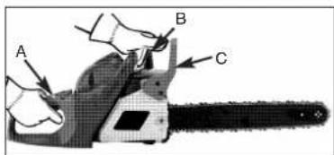
Close-up of a mechanical power shaver with labeled component A (no text or symbols beyond label)Abb. 18A

natural_image
Close-up of a mechanical component with labeled parts B and C (no readable text or symbols beyond labels)Abb. 18B
• TREIBSTOFF-FILTER

natural_image
Close-up of a mechanical component with a tool and labeled point A (no readable text or symbols)Abb. 19
• FUNKENGITTER
natural_image
Close-up of a mechanical component with labeled point A (no text or symbols beyond label)Abb. 21A
text_image
Close-up of hands holding a tool with labeled points C and B, likely indicating a component or device.Abb. 21B
natural_image
Close-up of a mechanical component with a hand holding a tool, no visible text or symbolsAbb. 22
natural_image
Illustration of hands using a tool to adjust or install a mechanical component (no text or symbols visible)Abb. 23
D
text_image
Technical diagram showing hands using a tool to adjust a component with 30-degree angle and 1/2 scale indicatorAbb. 25 Abb. 26
natural_image
Diagram of a mechanical assembly with conveyor and clamped components (no text or symbols)| Read the user manual before using the machine | Wear safety shoes to protect your feet. | ||
| (B200H) | On all jobs performed with the saw you must always wear safety goggles to guard your eyes from flying materials/objects and a sound-proof helmet, ear plugs or the like to protect your hearing. Wear a safety helmet if there is a risk of objects falling on you from above. | Protect yourself from saw kickback. Hold the chain saw securely with both hands during use. | |
| Make sure that the chain brake is released. Pull back the handle/chain brake before operating. | |||
| Noise emission complies with Directive 2000/14/ECI | |||
| Wear gloves to protect your hands. | Warning! Danger! |
WARNING! When using gas tools, basic safety precautions, including the following, should always be followed to reduce the risk of serious personal injury and/or damage to the unit.
Read all these instructions before operating this product and save these instructions.
-
DO NOT operate a chain saw with one hand! Serious injury to the operator, helpers, bystanders, or any combination of these persons may result from one-handed operation. A chain saw is intended for two-handed use.
-
DO NOT operate a chain saw when you are fatigued.
-
Use safety footwear, snug-fitting clothing, protective gloves, and eye, hearing and head protection devices.
-
Use caution when handling fuel. Move the chain saw at least 10 feet (3m) from the fueling point before starting the engine.
-
DO NOT allow other persons to be near when starting or cutting with the chain saw. Keep bystanders and animals out of the work area.
-
DO NOT start cutting until you have a clear work area, secure footing, and a planned retreat path from the falling tree.
-
Keep all parts of your body away from the saw chain when the engine is running.
-
Before you start the engine, make sure that the saw chain is not contacting anything.
-
Carry the chain saw with the engine stopped, the guide bar and saw chain to the rear, and the muffler away from your body.
-
NEVER use a chainsaw which is damaged, incorrectly set or incompletely and loosely assembled. Make sure that the chainsaw is switched off when releasing the chain brake.
-
Shut off the engine before setting the chain saw down.
-
Use extreme caution when cutting small size brush and saplings because slender material may catch the saw chain and be whipped toward you or pull you off balance.
-
When cutting a limb that is under tension, be alert for springback so that you will not be struck when the tension in the wood fibers is released.
-
Keep the handles dry, clean, and free of oil or fuel mixture.
-
Operate the chain saw only in well-ventilated areas.
-
DO NOT operate a chain saw in a tree unless you have been specifically trained to do so.
-
All chain saw service, other than the items listed in the user manual safety and maintenance instructions, should be performed by competent chain saw service personnel.
-
When transporting your chain saw, use the appropriate guide bar scabbard.
-
DO NOT operate your chain saw near or around flammable liquids or gases whether in or out of doors.
An explosion and/or fire may result.
-
Do not tank fuel, oil or lubrication when the engine of chain saw is running.
-
USE THE RIGHT TOOL: Cut wood only. Do not use the chain saw for purposes for which it was not intended. For example, do not use the chain saw for cutting plastic, masonry, or nonbuilding materials.
NOTE: This appendix is intended primarily for the consumer or occasional user. These models are intended for infrequent use by homeowners, cottagers, and campers, and for such general applications as clearing, pruning, cutting firewood, etc. They are not intended for prolonged use. If the intended use involves prolonged periods of operation, this may cause circulatory problems in the user's hands due to vibration. It may be appropriate to use
KICKBACK SAFETY PRECAUTIONS
a saw having an anti-vibration feature such as the models covered in this manual with the suffix Anti-Vibration. Kickback may occur when the nose or tip of the guide bar touches an object, or when the wood closes in and pinches the saw chain in the cut. If the bar tip contacts, it may cause a lightning-fast reverse reaction, kicking the guide bar up and back towards the operator. Pinching the saw chain along the top of the guide bar may push the guide bar rapidly back towards the operator. Either of these reactions may cause you to lose control of the saw, which could result in serious personal injury. Do not rely exclusively upon the safety devices built into your saw. As a chain saw user, you should take several steps to keep your cutting jobs free from accident or injury.
-
With a basic understanding of kickback, you can reduce or eliminate the element of surprise. Sudden surprise contributes to accidents.
-
Keep a good firm grip on the saw with both hands, the right hand on the rear handle, and the left hand on the front handle, when the engine is running. Use a firm grip with thumbs and fingers encircling the chain saw handles. A firm grip will help you reduce kickback and maintain control of the saw. Don't let go.
-
Make sure that the area in which you are cutting is free from obstructions. Do not let the nose of the guide bar contact a log, branch, or any other obstruction which could be hit while you are operating the saw.
-
Cut at high engine speeds.
-
Do not overreach or cut above shoulder height.
-
Follow manufacturer's sharpening and maintenance instructions for the saw chain.
-
Only use replacement bars and chains specified by the manufacturer or the equivalent.
NOTE: Low-kickback saw chain is chain that has met the kickback performance.
IMPORTANT SAFETY
A safety sign is fitted to the chain saw's fan filter cover. This label, along with the safety instructions on these pages, should be carefully read before attempting to operate this unit.
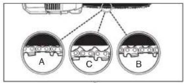
• HOW TO READ SYMBOLS AND COLORS (FIG. 1)

WARNING: RED Used to warn that an unsafe procedure should not be performed.
GREEN
RECOMMENDED
+
Fig. 1
3
Recommended cutting procedure.
WARNING
1. Beware of kick back.
2. Do not attempt to hold saw with one hand.
3. Avoid bar nose contact.
RECOMMENDED
4. Hold Saw properly with both hands.
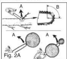
• DANGER! BEWARE OF KICKBACK!

WARNING: Kickback can lead to dangerous loss of control of the chain saw and result in serious or fatal injury to the saw operator or to anyone standing close by. Always be alert. Rotational kickback and pinch-kickback are major chain saw operational dangers and the leading cause of most accidents.
KICKBACK may occur when the NOSE or TIP of the guide bar touches an object, or when wood closes in and pinches the saw chain in the cut.
Tip contact in some cases may cause a lightning-fast reverse reaction, kicking the guide bar up and back toward the operator.
PINCHING the saw chain along the BOTTOM of the guide bar may PULL the saw forward away from the operator. PINCHING the saw chain along the TOP of the guide bar may PUSH the guide bar rapidly back toward the operator.
Any of these reactions may cause you to lose control of the saw, which could result in serious personal injury.
text_image
A B A A Fig. 2A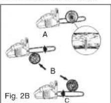
flowchart
graph TD
    A["Component A"] --> B["Component B"]
    B --> C["Component C"]
    style A fill:#f9f,stroke:#333
    style B fill:#ccf,stroke:#333
    style C fill:#cfc,stroke:#333
BEWARE OF:
ROTATIONAL KICKBACK THE PUSH
(Fig. 2A)
(PINCH KICKBACK)
AND PULL REACTIONS
(Fig. 2B)
A = Kickback path
B = Kickback reaction zone
A = Pull
B = Solid objects
C = Push
TECHNICAL DATA
Engine displacement 42 cm
Maximum drive power 1.7 kW
Cutter rail length 18" (45cm)
Cutting length 40 cm
Chain gap 10 mm
Chain thickness 1.3 mm
Idle speed 3,100 min ^-1 ± 10%
max. Speed 8000 min
Tank capacity 400 ml
Oil tank capacity 220 ml
Anti-vibration function Yes
Teeth 9
Chain brake Yes
Clutch Yes
Automatic chain lubrication Yes
Low-kickback chain Yes
Net weight without chain and chain bar 5.6 kg
Net weight 6.5 kg
Petrol consumption approx. 1.5 kg/h
Sound pressure level 103 dB(A)
Working pressure level 114 dB(A)
Braking time from working speed 0.07 s
Vibration 11.34 m/s²
GENERAL INFORMATION

text_image
Labeled diagram of a chain drive with numbered parts for identification and assembly reference.- Chain bar
- Saw chain
- Chain tensioning screw
- Spark mesh(inside exhaust)
- Chain brake lever / front hand guard
- Front handle
- Starter handle
- Spark plug
-
Air filter cover
-
Fuel pump
- Safety lock
- Oil tank cap
- Fan housing
- Fuel tank cap
- Rear handle / bootstrap
- Operating switch
- Choke / (carburetor setting)
- Bar fastening nut
-
Throttle lever
-
Chain catch
- Chain wheel trim
- Stop claw
- Chain guard
SAFETY FEATURES
Numbers preceding the descriptions correspond with the numbers on preceding page to help you locate the safety feature.
2 LOW KICKBACK SAW CHAIN helps significantly reduce kickback, or the intensity of kickback, due to specially designed depth gauges and guard links.
5 CHAIN BRAKE LEVER / HAND GUARD protects the operator's left hand in the event it slips off the front handle while saw is running.
5 CHAIN BRAKE is a safety feature designed to reduce the possibility of injury due to kickback by stopping a moving saw chain in milliseconds. It is activated by the CHAIN BRAKE lever.
16 STOP SWITCH immediately stops the engine when tripped. Stop switch must be pushed to ON position to start or restart engine.
11 SAFETY TRIGGER prevents accidental acceleration of the engine. Throttle trigger (19) cannot be squeezed unless the safety latch is depressed.
20 CHAIN CATCHER reduces the danger of injury in the event saw chain breaks or derails during operation. The chain catcher is designed to intercept a whipping chain.
NOTE: Study your saw and be familiar with its parts.
GB
ASSEMBLY INSTRUCTIONS
• TOOLS FOR ASSEMBLY
You will need these tools to assemble your chain saw: 1. Ring wrench SW 16
- Screwdriver / spark plug wrench
• ASSEMBLY REQUIREMENTS

WARNING: DO NOT start saw engine until unit is properly prepared.
Your new chain saw will require adjustment of chain, filling the fuel tank with correct fuel mixture and filling the oil tank with lubricating oil before the unit is ready for operation.
Read the entire user manual before attempting to operate your unit. Pay particular attention to all safety precautions.
This manual contains not only safety information but also general information on how to assemble, operate and service the saw.
• GUIDE BAR / SAW CHAIN / CLUTCH COVER INSTALLATION

WARNING: Always wear protective gloves when handling chain.
TO INSTALL GUIDE BAR:
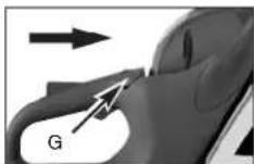
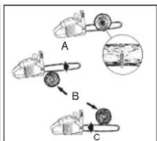
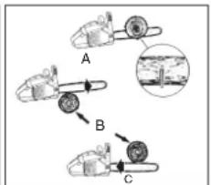
To ensure the bar and chain receive oil, ONLY USE THE ORIGINAL STYLE BAR with the oil passage hole (A) as illustrated above (Fig. 3A).
- Make sure the Chain brake lever is pulled back into the DISENGAGED position (Fig. 3B)
- Remove the bar fastening nut (B). Remove the chain brake cover (C) by pulling it straight out with a strong tug (Fig. 3C).
Note: The chain may sag a little. This is normal. - Using a screwdriver, run the adjustment screw (D) COUNTERCLOCKWISE until the TANG (E) (projecting prong) is to the end of its travel toward the clutch drum and sprocket (Fig. 3D).
- Place the slotted end of the guide bar over the bar bolts (F). Position the bar so that the adjustment TANG fits into the lower hole (G) on the guide bar (Fig. 3E).
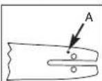
Fig. 3A
Fig. 3B
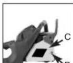
Fig. 3C
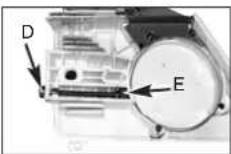
Fig. 3D
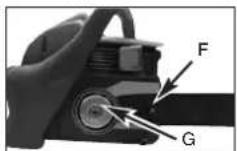
Fig. 3D
TO INSTALL SAW CHAIN:
- Spread chain out in a loop with cutting edges (A) pointing CLOCKWISE around loop (Fig. 4A).
- Slip the chain around the sprocket (B) behind the clutch (C). Make sure the links fit between the sprocket teeth (Fig. 4B).
- Guide the drive links into the groove (D) and around the end of the bar (Fig. 4B).
NOTE: The saw chain may droop slightly on the lower part of bar. This is normal.
- Pull the chain bar forward until the chain is closely seated. Make sure that all the drive links are in the groove of the bar.
- Install the clutch cover and tighten the 2 screws. Make sure the chain does not slip off of the bar. Install the 2 nuts hand tight and follow tension adjustment instructions in Section SAW CHAIN TENSION ADJUSTMENT.
NOTE: The guide bar retaining nuts are installed only hand tight at this point because saw chain adjustment is required. Follow instructions in Section SAW CHAIN
TENSION ADJUSTMENT.
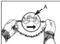
Abb. 4A
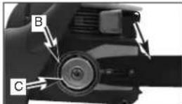
Abb. 4B
• SAW CHAIN TENSION ADJUSTMENT
Proper tension of saw chain is extremely important and must be checked before starting, as well as during any cutting operation.
Taking the time to make needed adjustments to the saw chain will result in improved cutting performance and prolonged chain life.

WARNING: Always wear heavy duty gloves when handling saw chain or making saw chain adjustments.
TO ADJUST SAW CHAIN:
- Hold nose of guide bar up and turn adjustment screw (D) CLOCKWISE to increase chain tension. Turning screw COUNTERCLOCKWISE will decrease amount of tension on chain. Ensure the chain fits snugly all the way around the guide bar (Fig. 5).
- After making adjustment, and while still holding nose of bar in the uppermost position, tighten the bar retaining nuts securely. Chain has proper tension when it has a snug fit all around and can be pulled around by gloved hand.
NOTE: If chain is difficult to rotate on guide bar or if it binds, too much tension has been applied. This requires minor adjustment as follows:
A. Loosen the bar retaining nut so they are finger tight. Decrease tension by turning the bar adjustment screw COUNTERCLOCKWISE slowly. Move chain back and forth on bar. Continue to adjust until chain rotates freely, but fits snugly. Increase tension by turning bar adjustment screw CLOCKWISE.
B. When saw chain has proper tension, hold nose of bar in the uppermost position and tighten the bar retaining nut securely.
GB

CAUTION: A new saw chain stretches, requiring adjustment after as few as 5 cuts. This is normal with a new chain, and the interval between future adjustments will lengthen quickly.
natural_image
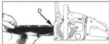
Technical line drawing of a mechanical component with labeled part D (no text or symbols beyond label)Abb. 5

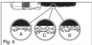
CAUTION: If saw chain is TOO LOOSE or TOO TIGHT, the sprocket, bar, chain, and crankshaft bearings will wear more rapidly. Study Fig. 6 for information concerning correct cold tension (A), correct warm tension (B), and as a guide for when saw chain needs adjustment (C).
text_image
Fig. 6• CHAIN BRAKE MECHANICAL TEST
Your chain saw is equipped with a Chain brake that reduces possibility of injury due to kickback. The brake is activated if pressure is applied against brake lever when, as in the event of kickback, operator's hand strikes the lever. When the brake is actuated, chain movement stops abruptly.

WARNING: The purpose of the chain brake is to reduce the possibility of injury due to kickback; however, it cannot provide the intended measure of protection if the saw is operated carelessly. Always test the chain brake before using your saw and periodically while on the job.
TO TEST CHAIN BRAKE:
- The Chain brake is DISENGAGED (chain can move) when BRAKE LEVER IS PULLED BACK AND LOCKED (Fig. 7A).
- The Chain brake is ENGAGED (chain is stopped) when brake lever is in forward position. You should not be able to move chain (Fig. 7B).
NOTE: The brake lever should snap into both positions. If strong resistance is felt, or lever does not move into either position, do not use your saw. Take it immediately to a professional Service Center for repair.

Fig. 7A Fig. 7B

FUEL AND LUBRICATION
• FUEL
Use regular grade unleaded gasoline mixed with 40:1 custom 2-cycle engine oil for best results.

WARNING: Never use straight gasoline in your unit. This will cause permanent engine damage and void the manufacturer's warranty for that product. Never use a fuel mixture that has been stored for over 90 days.

WARNING: If 2-cycle lubricant is to be used, it must be a premium grade oil for 2-cycle air cooled engines mixed at a 40:1 ratio. Do not use any 2-cycle oil product with a recommended mixing ratio of 100:1. If insufficient lubrication is the cause of engine damage, it voids the manufacturer's engine warranty for that occurrence.
• MIXING FUEL
Mix fuel with 2 cycle oil in an approved container. Shake container to ensure thorough mix.

WARNING: Lack of lubrication voids engine warranty.
• FUEL AND LUBRICATION

natural_image
Silhouette of a fuel pump with a plus sign and a droplet symbol (no text or labels)
Gasoline and Oil Mix 40:1 Oil Only
• RECOMMENDED FUELS
Some conventional gasolines are being blended with oxygenates such as alcohol or an ether compound to meet clean air standards. Your engine is designed to operate satisfactorily on any gasoline intended for automotive use including oxygenated gasolines. It is recommended to use unleaded petrol as fuel.
• CHAIN AND BAR LUBRICATION
Always refill the chain oil tank each time the fuel tank is refilled. We recommend using Chain, Bar and Sprocket Oil, which contains additives to reduce friction and wear and to assist in the prevention of pitch formation on the bar and chain.
GB
OPERATING INSTRUCTIONS
• ENGINE PRE-START CHECKS

WARNING: Never start or operate the saw unless the bar and chain are properly installed.
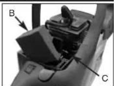
- Fill the fuel tank (A) with the correct fuel mix (Fig. 8).
- Fill the oil tank (B) with the correct chain and bar oil (Fig. 8).
- Before you start the engine, make sure that the chain brake (C) is released.
• STARTING THE ENGINE
- To start the saw, push the switch (ON/OFF switch) to the ON (I) position (Fig. 9A).
- Pull out the choke (A) to the point where it latches in place (Fig. 9B).
- Press the fuel pump (B) 10 times (Fig. 9C).
- Place the saw on a firm and level surface. Hold the saw securely with your foot as illustrated. Tug sharply on the starter 4 times. Watch the chain in case it runs (Fig. 9D).
NOTE: If the engine sounds as if it wants to start before the 4th tug, end the tugging of the starter and proceed as described in the next step.
- Push in the choke (G) as far it will go (Fig. 9E).
- Hold the saw securely and tug sharply on the starter 4 times. The engine should start.
- Let the engine run for 10 seconds to warm up. Press the trigger (H) and put it into idle (Fig. 9F).
- If the engine does not start up, repeat the above
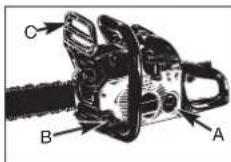
Abb. 8 Abb. 9A
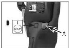
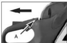
Abb. 9B Abb. 9C
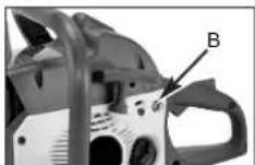

Abb. 9D Abb. 9E
steps.
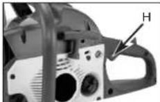
Abb. 9F Abb. 9G

- RESTARTING THE ENGINE WHEN IT IS HOT
- Make sure that the switch is set to ON
- Tug sharply on the starter rope 4 times. The engine should start.
- If the engine does not start up, refer to the instructions in the section: CHECKS TO BE CARRIED OUT BEFORE STARTING THE ENGINE
• STOPPING THE ENGINE
- Let go of the throttle lever and wait until the engine is running in idle mode.
- Push the STOP switch down to stop the engine (Fig. 9G).
NOTE: To stop the engine in an emergency, activate the chain brake and push the STOP switch down.
Test the chain brake periodically to ensure proper function. Perform a chain brake test prior to initial cutting, following extensive cutting, and definitely following any Chain brake service.
TEST CHAIN BRAKE AS FOLLOWS (Fig. 10):
- Place saw on a clear, firm, flat surface.
- Start engine.
- Grasp the rear handle (A) with your right hand.
- With your left hand, hold the front handle (B) [not chain brake lever (C)] firmly.
- Squeeze the throttle trigger to 1/3 throttle, then immediately activate the chain brake lever (C)

WARNING: Activate the chain brake slowly and deliberately. Keep the chain from touching anything; don't let the saw tip forward.
- Chain should stop abruptly. When it does, immediately release the throttle trigger.

WARNING: If chain does not stop, turn engine off and take your unit to the nearest Talon Authorized Service Center for service.
- If chain brake functions properly, turn the engine off and return the chain brake to the DISENGAGED position.
text_image
A B CAbb. 10
GB
• SAW CHAIN / BAR LUBRICATION
Adequate lubrication of the saw chain is essential at all times to minimize friction with the guide bar.
Never starve the bar and chain of oil. Running the saw with too little oil will decrease cutting efficiency, shorten saw chain life, cause rapid dulling of chain, and cause excessive wear of bar from overheating. Too little oil is evidenced by smoke, bar discoloration or pitch build-up.
NOTE: Saw chain stretches during use, particularly when it is new, and it will occasionally be necessary to adjust and tighten it. New chain will require adjustment after about 5 minutes of operation.
• AUTOMATIC OILER
Your chain saw is equipped with an automatic gear driven oiler system. The oiler automatically delivers the proper amount of oil to the bar and chain. As the engine speed increases, so does the oil flow to the bar pad. There is no flow adjustment. The oil reservoir will run out at approximately the same time as the fuel supply runs out.
GENERAL CUTTING INSTRUCTIONS
• FELLING
Felling is the term for cutting down a tree. Small trees up to 6-7 inches (15-18cm) in diameter are usually cut in a single cut. Larger trees require notch cuts. Notch cuts determine the direction the tree will fall.
FELLING A TREE:

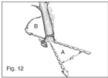
WARNING: A retreat path (A) should be planned and cleared as necessary before cuts are started. The retreat path should extend back and diagonally to the rear of the expected line of fall, as illustrated in Fig. 12.

CAUTION: If felling a tree on sloping ground, the chain saw operator should keep on the uphill side of the terrain, as the tree is likely to roll or slide downhill after it is felled.
IMPORTANT: Felling trees is prohibited without the necessary training!
NOTE: Direction of fall (B) is controlled by the notching cut. Before any cuts are made, consider the location of larger branches and natural lean of the tree to determine the way the tree will fall.
text_image
B A Fig. 12
WARNING: Do not cut down a tree during high or changing winds or if there is a danger to property. Consult a tree professional. Do not cut down a tree if there is a danger of striking utility wires; notify the utility company before making any cuts.
GENERAL GUIDELINES FOR FELLING TREES (Fig. 15):
Normally felling consists of 2 main cutting operations, notching (C) and making the felling cut (D). Start making the upper notch cut (C) on the side of the tree facing the felling direction (E). Be sure you don't make the lower cut too deep into the trunk.
The notch (C) should be deep enough to create a hinge (F) of sufficient width and strength. The notch should be wide enough to direct the fall of the tree for as long as possible.

WARNING: Never walk in front of a tree that has been notched. Make the felling cut (D) from the other side of the tree and 1.5 - 2.0 inches (3-5 cm) above the edge of the notch (C) (Fig. 13)
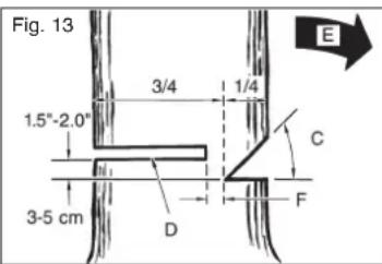
text_image
Fig. 13 1.5"-2.0" 3-5 cm 3/4 1/4 C D F ENever saw completely through the trunk. Always leave a hinge. The hinge guides the tree. If the trunk is completely cut through, control over the felling direction is lost.
Insert a wedge or felling lever in the cut well before the tree becomes unstable and starts to move. This will prevent the guidebar from binding in the felling cut if you have misjudged the falling direction. Make sure no bystanders have entered the range of the falling tree before you push it over.

WARNING: Before making the final cut, always recheck the area for bystanders, animals or obstacles.
FELLING CUT:
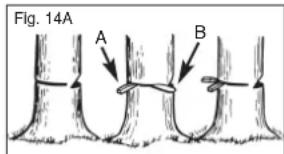
- Use wooden or plastic wedges (A) to prevent binding the bar or chain (B) in the cut. Wedges also control felling (Fig. 14A).
- When diameter of wood being cut is greater than the bar length, make 2 cuts as shown (Fig. 14B).
text_image
Fig. 14A A B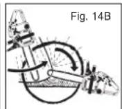

WARNING: As the felling cut gets close to the hinge, the tree should begin to fall. When tree begins to fall, remove saw from cut, stop engine, put chain saw down, and leave area along retreat path (Fig. 12).
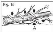
• LIMBING
Limbing a tree is the process of removing the branches from a fallen tree. Do not remove supporting limbs (A) until after the log is bucked (cut) into lengths (Fig. 15). Branches under tension should be cut from the bottom up to avoid binding the chain saw.

WARNING: Never cut tree limbs while standing on tree trunk.
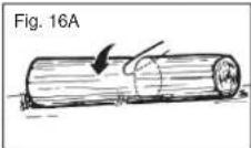
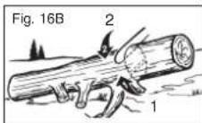
•BUCKING
Bucking is cutting a fallen log into lengths. Make sure you have a good footing and stand uphill of the log when cutting on sloping ground. If possible, the log should be supported so that the end to be cut off is not resting on the ground. If the log is supported at both ends and you must cut in the middle, make a downward cut halfway through the log and then make the undercut. This will prevent the log from pinching the bar and chain. Be careful that the chain does not cut into the ground when bucking as this causes rapid dulling of the chain. When bucking on a slope, always stand on the uphill side.
- Log supported along entire length: Cut from top (overbuck), being careful to avoid cutting into the ground (Fig. 16A).
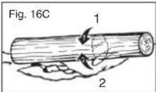
- Log supported on 1 end: First, cut from bottom (underbuck) 1/3 diameter of log to avoid splintering. Second, cut from above (overbuck) to meet first cut and avoid pinching (Fig. 16B).
- Log supported on both ends: First, overbuck 1/3 diameter of log to avoid splintering. Second, underbuck to meet first cut and avoid pinching (Fig. 16C).
NOTE: The best way to hold a log while bucking is to use a sawhorse. When this is not possible, the log should be raised and supported by the limb stumps or by using supporting logs. Be sure the log being cut is securely supported.
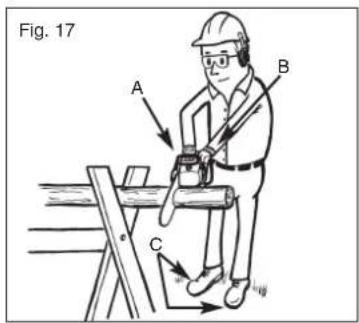
•BUCKING USING A SAWHORSE
For personal safety and ease of cutting, the correct position for vertical bucking is essential (Fig. 17).
VERTICAL CUTTING:
A. Hold the saw firmly with both hands and keep the saw to the right of your body while cutting.
B. Keep the left arm as straight as possible.
C. Keep weight on both feet.

CAUTION: When working with the saw, always make sure that the saw chain and chain bar are sufficiently lubricated.
text_image
Fig. 17 A B CMAINTENANCE INSTRUCTIONS
All chain saw service, other than items listed here in your user manual maintenance instructions, should be performed professional.
• PREVENTIVE MAINTENANCE
A good preventive maintenance program of regular inspection and care will increase life and improve performance of your Talon chain saw. This maintenance checklist is a guide for such a program. Cleaning, adjustment, and parts replacement may be required, under certain conditions, at more frequent intervals than those indicated.
| Maintenance CHECKLIST USE OPERATION | EACH | |||
| ITEM ACTION | √ | 10 | 20 | |
| Screws/Nuts/Bolts Inspect/Tighten | √ | |||
| Air Filter Clean or Replace | √ | |||
| Fuel Filter/Oil Filter Replace | √ | |||
| Spark Plug Clean/Adjust/Replace | √ | |||
| Spark Arrester Screen | Inspect | √ | ||
| Fuel Hoses | Inspect | √ | ||
| Replace as Required | ||||
| Chain brake components | Inspect | √ | ||
| Replace as Required | ||||
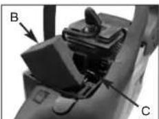
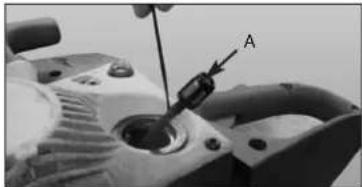
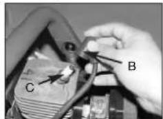
• AIR FILTER

CAUTION: Never operate saw without the air filter. Dust and dirt will be drawn into engine and damage it. Keep the air filter clean!
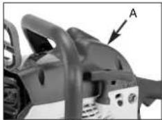
TO CLEAN AIR FILTER:
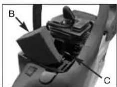
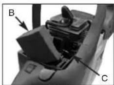
- Remove the top cover (A) by loosening the cover retaining screws. Cover will lift off. (Fig. 18a)
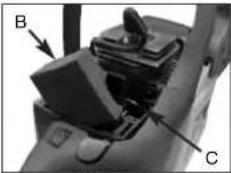
- Lift the air filter (B) out of air-box (C) (Fig. 18b)
- Clean air filter. Wash filter in clean, warm, soapy water. Rinse in clear, cool water. Air dry completely.
NOTE: It is advisable to have a supply of spare filters. - Install air filter. Install engine / air filter cover. Make sure cover fits properly. Tighten the cover retaining screws securely.

WARNING: Never perform maintenance when the engine is hot, to avoid any chance of burning hands or fingers.
GB
natural_image
Close-up of a mechanical power shaver with labeled component A (no text or symbols beyond label)Abb. 18A
natural_image
Close-up of a mechanical component with labeled parts B and C, showing internal structure without any readable text or symbols.Abb. 18B
• FUEL FILTER

CAUTION: Never use the saw without a fuel filter. After 20 hours in operation the fuel filter should be cleaned or, in case of damage, replaced. Be sure to empty the fuel tank before changing the filter.
- Remove the fuel tank cap.
- Bend a piece of soft wire.
- Reach into fuel tank opening and hook fuel line. Carefully pull the fuel line toward the opening until you can reach it with your fingers.
NOTE: Do not pull hose completely out of tank.
-
Lift filter (A) out of tank (Fig. 19).
-
Pull off the filter with a twist and clean it; if the filter is damaged, dispose of it.
-
Insert a new filter. Place one end of the filter into the tank opening. Make sure that the filter is seated in the lower corner of the tank. If necessary, use a long screwdriver to move the filter to its correct position, taking care not to damage in the process.
-
Fill tank with fresh fuel / oil mixture. See Section
FUEL AND LUBRICATION. Install fuel cap.
natural_image
Close-up of a mechanical component with a tool inserted, labeled 'A' pointing to a feature (no readable text or symbols beyond label)Abb. 19
- SPARK MESH
NOTE: Engine performance is greatly reduced by a dirty spark mesh.
- Release the chain brake. Remove the 2 screws (A) and take out the muffler (Fig. 20A).
- Remove the 2 screws holding the cover (C), see Fig. 20B.
- Dispose of the old spark mesh (D) and insert a new one.
- Assemble the exhaust parts in reverse order and fasten again on the cylinder. Tighten the screws.
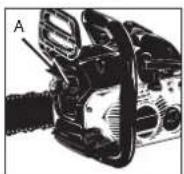
Fig. 20A
text_image
A B C DFig. 20B
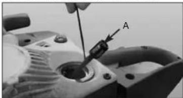
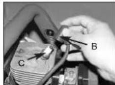
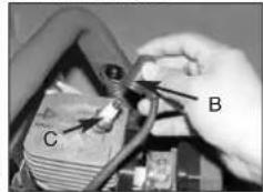
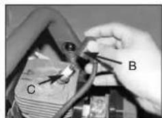
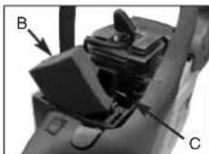
- SPARK PLUG
NOTE: For efficient operation of saw engine, spark plug must be kept clean and properly gapped.
- Push STOP switch down.
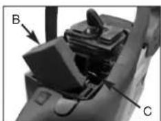
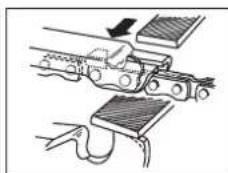
- Remove the cover (A) by undoing the cover fastening screws (Fig. 21A).
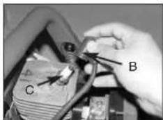
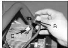
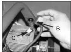
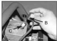
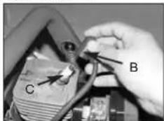
- Disconnect the ignition cable (B) from the spark plug by pulling and twisting it simultaneously (Fig. 21B).
- Reinstall a new spark plug, gapped at 0.6mm.
natural_image
Close-up of a mechanical component with labeled point A (no readable text or symbols)Abb. 21A
text_image
Close-up of a hand holding a component with labeled parts C and B, likely indicating parts of a device or wiring.Abb. 21B
• CARBURETOR ADJUSTMENT
The carburetor was pre-set at the factory for optimum performance. If further adjustments are necessary, please take your unit to the nearest professional.
• STORING A CHAIN SAW

CAUTION: Never put a chain saw into storage for longer than 30 days without carrying out the following steps.
Storing a chain saw for longer than 30 days requires storage maintenance. Unless the storage instructions are followed, fuel remaining in the carburetor will evaporate, leaving gum-like deposits. This could lead to difficult starting and result in costly repairs.
- Remove the fuel tank cap slowly to release any pressure in tank. Carefully drain the fuel tank.
- Start the engine and let it run until the unit stops to remove fuel from carburetor.
- Allow the engine to cool (approx. 5 minutes).
- Using a spark plug wrench, remove the spark plug.
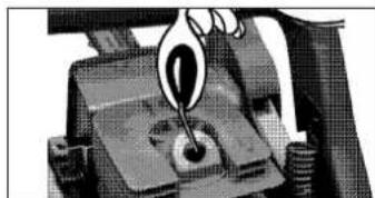
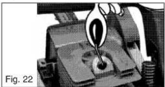
- Pour 1 teaspoon of clean 2-cycle oil into the combustion chamber. Pull starter rope slowly several times to coat internal components. Replace spark plug (Fig. 22).
NOTE: Store the unit in a dry place and away from possible sources of ignition such as a furnace, gas hot water heater, gas dryer, etc.
natural_image
Close-up of a mechanical component with a hand holding a knob (no visible text or symbols)Fig. 22
- Remove spark plug.
- Pull starter rope briskly to clear excess oil from combustion chamber.
- Clean the spark plug and check that the electrode gap is correct.
- Prepare unit for operation.
- Fill fuel tank with proper fuel / oil mixture. See FUEL AND LUBRICATION Section.
• CHAIN BAR MAINTENANCE
Regular lubrication of the chain bar (guide rail for the chain and teeth) is essential. The chain bar needs the maintenance described in the following section in order for the saw to work at an optimum level of performance

CAUTION: The sprocket tip on your new saw has been pre-lubricated at the factory. Failure to lubricate the guide bar sprocket tip as explained below will result in poor performance and seizure, voiding the manufacturer's warranty.
TOOLS FOR LUBRICATION:
The Lube Gun (optional) is recommended for applying grease to the guide bar sprocket tip. The Lube Gun is equipped with a needle nose tip which is necessary for the efficient application of grease to the sprocket tip.
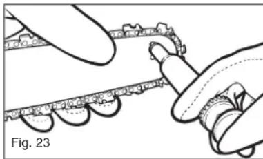
TO LUBRICATE SPROCKET TIP:
Lubrication of the sprocket tip is recommended after 10 hours of use or once a week, which ever occurs first. Always thoroughly clean guide bar sprocket tip before lubrication.
NOTE: The saw chain does not have to be removed in order to lubricate the teeth of the chain bar. Lubrication is possible during work, with the engine switched off.

WARNING: Wear heavy duty work gloves when handling the bar and chain.
- Move the STOP switch down.
- Clean the guide bar sprocket tip.
- Using the Lube Gun (optional), insert needle nose into the lubrication hole and inject grease until it appears at outside edge of sprocket tip (Fig .23).
- Rotate saw chain by hand. Repeat lubrication procedure until the entire sprocket tip has been greased.
natural_image
Illustration of hands assembling a mechanical component (no text or symbols visible)GUIDE BAR MAINTENANCE:
Most guide bar problems can be prevented merely by keeping the chain saw well maintained.
Insufficient guide bar lubrication and operating the saw with chain that is TOO TIGHT will contribute to rapid bar wear.
To help minimize bar wear, the following guide bar maintenance procedures are recommended.

WARNING: Always wear protective gloves during maintenance operations. Do not carry out maintenance when the engine is hot.
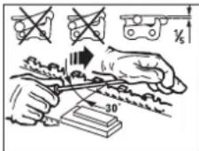
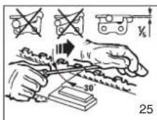
CHAIN SHARPENING:
Chain sharpening requires special tools to ensure that cutters are sharpened at the correct angle and depth. For the inexperienced chain saw user, we recommend that the saw chain be professionally sharpened by the nearest professional Service Center. If you feel comfortable sharpening your own saw chain, special tools are available from the professional Service Center.
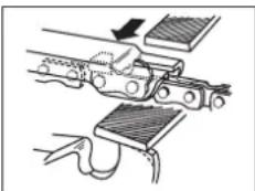
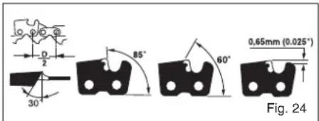
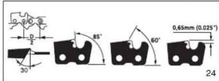
CHAIN SHARPENING - The pitch of the chain (Fig. 24) is 3/8" LoPro x .050".
Sharpen the chain using protective gloves and a round file of 3 / 16^ (4.8mm).
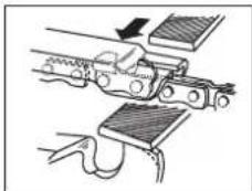
Always sharpen the cutters only with outward strokes (Fig. 25) observing the values given in Fig. 24.
After sharpening, the cutting links must all have the same width and length.
text_image
0.65mm (0.025°) Fig. 24
WARNING: A sharp chain produces well-defined chips. When your chain starts to produce sawdust, it is time to sharpen.
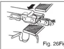
After every 3-4 times the cutters have been sharpened you need to check the height of the depth gauges and, if necessary, lower them using the flat file and template supplied optional, then round off the front corner. (Fig. 26)

WARNING: Proper adjustment of the depth gauge is as important as proper sharpening of the chain.
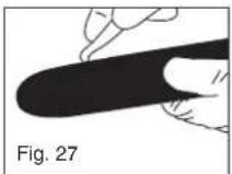
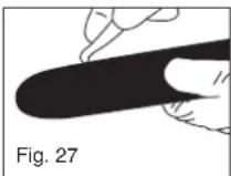
GUIDE BAR - The bar should be reversed every 8 working hours to ensure uniform wear.
Keep the bar groove and lubrication hole clean using the bar groove cleaner supplied optional. (Fig. 27)
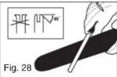
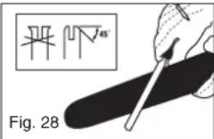
Check the bar rails frequently for wear and, if necessary, remove the burs and square-up the rails using the flat file. (Fig. 28)

WARNING: Never mount a new chain on a worn sprocket or self-aligning ring.
GB
BAR WEAR - Turn guide bar frequently at regular intervals (for example, after 5 hours of use), to ensure even wear on top and bottom of bar.
OIL PASSAGES - Oil passages on the bar should be cleaned to ensure proper lubrication of the bar and chain during operation.
NOTE: The condition of the oil passages can be easily checked. If the passages are clear, the chain will automatically give off a spray of oil within seconds of starting the saw. Your saw is equipped with an automatic oiler system.
• CHAIN MAINTENANCE
CHAIN TENSION:
Check the chain tension frequently and adjust as often as necessary to keep the chain snug on the bar, but loose enough to be pulled around by hand.
BREAKING IN A NEW SAW CHAIN:
A new chain and bar will need chain readjustment after as few as 5 cuts. This is normal during the break-in period, and the interval between future adjustments will begin to lengthen quickly.

WARNING: Never have more than 3 links removed from a loop of chain. This could cause damage to the sprocket.
CHAIN LUBRICATION:
Always make sure the automatic oiler system is working properly. Keep the oil tank filled with Chain, Bar and Sprocket Oil.
Adequate lubrication of the bar and chain during cutting operations is essential to minimize friction with the guide bar.
Never starve the bar and chain of lubricating oil. Running the saw dry or with too little oil will decrease cutting efficiency, shorten saw chain life, cause rapid dulling of chain, and lead to excessive wear of bar from overheating. Too little oil is evidenced by smoke or bar discoloration.
TROUBLE SHOOTING THE ENGINE
| PROBLEMUnit won't start or starts but will not run. | PROBABLE CAUSEIncorrect starting procedures.Incorrect carburetor mixture adjustment setting.Fouled spark plugFuel filter plugged. | CORRECTIVE ACTIONFollow instructions in the User Manual.Have carburetor adjusted by an Authorized Service Center.Clean / gap or replace plug.Replace fuel filter. |
| Unit starts, but engine has low power. | Incorrect lever position on choke.Dirty spark arrester screen.Dirty air filter.Incorrect carburetor mixture adjustment setting.The distance between the rotor and the ignition coil has changed | Move to RUN position.Replace spark arrester screen.Remove, clean and reinstall filter.Have carburetor adjusted by an Authorized Service Center.Arrange for an authorized Customer Service workshop to adjust the distance between the rotor and the ignition coil to 0.3-0.4 mm |
| Engine hesitates.No power under load. | Incorrect carburetor mixture adjustment setting. | Have carburetor adjusted by an Authorized Service Center. |
| Runs erratically. | Incorrectly gapped spark plug. | Clean / gap or replace plug. |
| Smokes excessively. | Incorrect carburetor mixture adjustment setting.Incorrect fuel mixture. | Have carburetor adjusted by an Authorized Service Center.Use properly mixed fuel (40:1 mixture). |
F
Recommended cutting procedures.
AVERTISSEMENT
text_image
Diagram illustrating a mechanical or physical process with labeled components A and B, showing motion paths and circular arrangements.Fig. 2A
flowchart
graph TD
    A["Component A"] --> B["Component B"]
    B --> C["Component C"]
    style A fill:#f9f,stroke:#333
    style B fill:#ccf,stroke:#333
    style C fill:#cfc,stroke:#333
Fig. 2B
ATTENTION AUX: REBONDS ROTATIFS (Figure 2A)
text_image
Labeled diagram of a chain drive with numbered parts for identificationnatural_image
Diagram of a person using a chain-linking tool to cut a tree trunk, with no visible text or symbols.5

natural_image
Close-up of a mechanical power shaver with labeled component A (no text or symbols beyond label)18A

natural_image
Close-up of a mechanical device with labeled parts B and C, showing no visible text or symbols beyond labels.18B
• FILTRE A ESSENCE

natural_image
Close-up of a mechanical component with a tool inserted, labeled 'A' pointing to a feature (no readable text or symbols beyond label)19
natural_image
Close-up of a car chassis frame with labeled component A (no text or symbols beyond label)21A
text_image
Close-up of a hand holding a component with labeled parts C and B, likely indicating parts of a device or circuit board.21B
natural_image
Close-up of a hand using a tool to press or inspect a mechanical component, labeled '22' (no text or symbols on the object itself)• REMISE EN SERVICE DE LA SCIE
natural_image
Illustration of hands adjusting a mechanical component with a textured surface (no text or symbols)ENTRETIEN DU GUIDE-CHAINE:
CHAIN SHARPENING - The pitch of the chain (Fig. 24) is 3/8" LoPro x .050".
Sharpen the chain using protective gloves and a round file of 3/16" (4.8mm).
Always sharpen the cutters only with outward strokes (Fig. 25) observing the values given in Fig. 24.
After sharpening, the cutting links must all have the same width and length.
After every 3-4 times the cutters have been sharpened you need to check the height of the depth gauges and, if necessary, lower them using the flat file and template supplied optional, then round off the front corner. (Fig. 26)
text_image
0,65mm (0.025°) 85° 60° 30° 24
WARNING: Proper adjustment of the depth gauge is as important as proper sharpening of the chain.
text_image
Technical diagram showing hand tooling with labeled angle 30° and coordinate axes X and Y, accompanied by mechanical diagrams.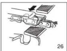
natural_image
Mechanical assembly diagram showing a conveyor belt and clamping mechanism (no text or symbols)F
text_image
Diagram illustrating mechanical or robotic motion with labeled components A and B, showing movement paths and circular objects.Fig. 2A
flowchart
graph TD
    A["Vehicle Component A"] --> B["Component B"]
    B --> C["Component C"]
    style A fill:#f9f,stroke:#333
    style B fill:#ccf,stroke:#333
    style C fill:#cfc,stroke:#333
Fig. 2B
CUIDESE DE:
EL CONTRAGOLPE (Figura 2A)
text_image
Labeled diagram of a chain drive with numbered parts for identification and assembly reference.natural_image
Technical line drawing of a mechanical cutting tool with labeled component D (no text or symbols beyond label)Abb. 5

natural_image
Three black icons: a fuel pump, a funnel with plus sign, and a car with droplet (no text or symbols)natural_image
Close-up of a mechanical power shaver with labeled component A (no text or symbols beyond label)Abb. 18A
natural_image
Close-up of a mechanical component with labeled parts B and C (no readable text or symbols beyond labels)Abb. 18B
natural_image
Close-up of a hand using a screwdriver to adjust or install a mechanical component (no visible text or symbols)Abb. 19
• REJILLA ANTICHISPAS
natural_image
Close-up of a mechanical component with labeled part A (no visible text or symbols)Abb. 21A
text_image
Close-up photo of hands holding a component with labeled parts C and B, likely from an electronics or circuit testing context.Abb. 21B
NOTE: Store the unit in a dry place and away from possible sources of ignition such as a furnace, gas hot water heater, gas dryer, etc.
natural_image
Close-up of a mechanical component with a hand holding a tool, labeled as Fig. 22 (no visible text or symbols on the object itself)natural_image
Illustration of hands using a tool to measure a small object, labeled 'Fig. 23' (no text or symbols on the diagram itself)E
MANTENIMIENTO DE LA BARRA GUIA:
natural_image
Diagram of a mechanical assembly with arrows indicating motion, no visible text or symbolsWARNING: Never mount a new chain on a worn sprocket or self-aligning ring.
text_image
Labeled diagram of a chain drive with numbered parts for identification and assembly reference.text_image
Diagram of a car interior with labeled parts A, B, C, and D showing directional arrows indicating movement or flow.Abb. 4A
Abb. 4B
STÄLLA IN KEDJESPÄNNINGEN
natural_image
Technical line drawing of a chain saw cutting a material, showing blade and gear assembly (no text or symbols)5

natural_image
Silhouette of a fuel pump with a plus sign and a droplet symbol (no text or labels)ALLMÄNNA INSTRUKTIONER FÖR SÅGNING
FÄLLNING
natural_image
Close-up of a mechanical component with labeled point A (no text or symbols beyond label)18A
natural_image
Close-up of a mechanical device with labeled parts B and C, showing no visible text or symbols beyond labels.18B
BRÄNSLEFILTER

natural_image
Close-up of a mechanical component with a tool and labeled point A (no readable text or symbols)19
GNISTGALLER
natural_image
Close-up of a mechanical component with labeled point A (no text or symbols beyond label)21A
text_image
Close-up photo of a hand holding a component labeled C and B, likely indicating parts of a device or circuit board.21B
STÄLLA IN FÖRGASAREN
natural_image
Close-up of a mechanical component with a hand holding a tool, no visible text or symbolsTA SÄGEN I DRIFT PÅ NYTT
natural_image
Illustration of hands using a tool to adjust or install a mechanical component (no text or symbols visible)23
UNDERHÅLLA SVÄRDET
text_image
0.65mm (0.025°) 85° 60° 30° D Z24

text_image
Diagram illustrating a mechanical or electrical process with labeled components and directional indicators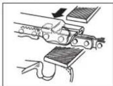
natural_image
Diagram of a mechanical device with clamping mechanism and connecting rod (no text or symbols)25 26
SYMBOLIT JA VÄRIT (KUVA 1)

text_image
Technical diagram of a chain drive with numbered parts for identification and assembly reference.TURVALLISUUSTOIMINNOT
text_image
Technical diagram showing a hand using a chainsaw with labeled component D5

natural_image
Simple black-and-white icon showing a fuel pump, plus sign, and droplet (no text or symbols)natural_image
Close-up of a mechanical component with labeled point A (no text or symbols beyond label)18A

natural_image
Close-up of a mechanical device with labeled parts B and C, showing internal components and wiring (no readable text or symbols beyond labels)18B
POLTTOAINESUODATIN

natural_image
Close-up of a mechanical component with a tool inserted, labeled 'A' pointing to a feature (no readable text or symbols beyond label)19
KIPINÄRISTIKKO
natural_image
Close-up of a mechanical component with labeled part A (no readable text or symbols)21A
text_image
Close-up of a hand holding a component with labeled parts C and B, likely indicating parts of a device or circuit.21B
KAASUTTIMEN SÄÄTÖ
natural_image
Close-up of a mechanical component with a hand holding a tool, no visible text or symbolsSAHAN UUDELLEENKÄYTTÖÖNOTTO
natural_image
Illustration of hands using a tool to adjust or install a chain-like structure (no text or symbols visible)TERÄLEVYN HUOLTO:
text_image
0.65mm (0.025°) 85° 60° 30° D 2text_image
Diagram illustrating a mechanical or electrical process with labeled components and symbols, including crossed-out tools and a 30-degree angle indicator.25 26
natural_image
Diagram of a mechanical assembly with a tool and clamped components (no text or symbols)FIN
Recommended cutting procedure.
Advarsel 3
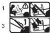
Fig. 1
text_image
Technical diagram of a chain drive with numbered parts and exploded viewnatural_image
Simple black-and-white icon showing a fuel pump, a plus sign, and a droplet (no text or symbols)
BENZIN OG OLIE/MIX 40 : 1 KUN OLIE
• KÆ DE OG SVÆ RD SM∅RELSEN
natural_image
Close-up of a mechanical component with labeled point A (no text or symbols beyond label)18A

natural_image
Close-up of a mechanical component with labeled parts B and C (no readable text or symbols beyond labels)18B
- Oliefilter
natural_image
Close-up of a mechanical component with a tool and labeled point A (no readable text or symbols)19
- GL∅DEGITTER
natural_image
Close-up of a mechanical component with labeled point A (no visible text or symbols)21A

text_image
C B21B
- Justering af karburator
natural_image
Close-up of a mechanical component with a hand holding a tool, labeled 'Fig. 22' (no readable text or symbols)IBRUGTAGNING AF SAVEN IGEN
natural_image
Illustration of hands assembling a chain with a tool, labeled Fig. 23 (no text or symbols on the diagram itself)text_image
Diagram illustrating a manual tooling process with labeled components and directional arrows, including a 30-degree angle indicator.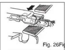
natural_image
Diagram of a robotic arm connecting a cart with sensors, labeled Fig. 26 (no text or symbols on the diagram itself)
text_image
Technical diagram of a chain drive with numbered parts for identification and assembly reference.natural_image
Diagram of a hand using a power tool to cut a black cable labeled 'D' (no text or symbols beyond label)5

natural_image
Simple black-and-white icon showing a fuel pump, plus sign, and droplet (no text or symbols)natural_image
Close-up of a mechanical component with labeled point A (no readable text or symbols)18A
natural_image
Close-up of a mechanical component with labeled parts B and C (no readable text or symbols beyond labels)18B
FILTRO DEL CARBURANTE

natural_image
Close-up of a mechanical component with a tool and labeled point A (no readable text or symbols)19
GRIGLIA PARASCINTILLE
CANDELA DI ACCENSIONE
natural_image
Close-up of a mechanical component with labeled point A (no visible text or symbols)21A
text_image
Close-up of a hand holding a tool with labeled points C and B, likely indicating a component or measurement.21B
natural_image
Close-up of a mechanical component with a hand holding a pointed tool, labeled Fig. 22 (no readable text or symbols)RIUTILIZZO DELLA MOTOSEGA
natural_image
Illustration of hands using a tool to adjust or install a mechanical component, labeled 'Fig. 23' (no text or symbols on the diagram itself)text_image
Technical diagram of a chain drive with numbered parts for identification and assembly reference.1 Glavna ili klizna vodilica
2 Lanac pile
3 Vijak za zatezanje lanca
4 Mrežica protiv iskrenja (unutra na ispušnom otvoru)
5 Poluga kočnice lanca/ prednja zaštita ruke
6 Prednia ručka
7 Bučka startera
8 Sviećica
9 Poklopac filtra za zrak
10 Pumpa za gorivo
11 Sigurnosna blokada
12 Poklopac spremnika za ulje
13 Kućište ventilatora
14 Poklopac spremnika za gorivo
15 Stražnja ručka/koljenasto crije-
vo
16 Sklopka za pogon
17 Poluga za prigušivanje (podešavanje rasplinjača)
18 Matica za pričvršćivanje
vodilice
19 Poluga gasa
20 Držač Ianca
21 Oplata lančanika
22 Graničnik čeliusti
23 Zaštita lanca
SIGURNOSNE FUNKCIJE
Brojevi u sljedećem opisu odgovaraju brojevima na prethodnoj strani čime se omogućava lakše pronalaženje sigurnosnih funkcija.
2 LANAC PILE S MALIM POVRATNIM UDARCEM
pomaže Vam sa specijalno razvijenim sigurnosnim napravama da uhvatite povratni udarac ili njihovu silu.
5 POLUGA ZA KOČENJE LANCA / ZAŠTITA RUKE
SIMBOLI I BOJE (SL. 1)
ZELENA PREPORUČENO

natural_image
Diagram of a hand operating a mechanical tool with a labeled component (no text or symbols present)5

OPREZ: Kad je lanac pile PRELABAV ili PRENAPET, brže se troše zupci, vodilica, lanac i ležaj koljenastog vratila. Slika 6 informira o ispravnoj hladnoj napetosti (A) i toploj napetosti (B), te služi kao uputa za ostala podešavanja lanca pile (C).
HR
text_image
A C B6
MEHANIČKI TEST KOČNICE LANCA
Lančana pila ima kočnicu lanca koja smanjuje ozljede uslijed opasnosti povratnog udaraca. Kočnica se aktivira kad se pritisne poluga kočnice i to u slučaju da npr. prilikom povratnog udarca korisnikova ruka udari o polugu. Kod aktiviranja kočnice lanac se isprekidano zaustavlja.

natural_image
Simple black-and-white icon showing a fuel pump, plus sign, and droplet (no text or symbols)
Mješavina benzina i ulja 40:1 Samo ulje
PREPORUČENA GORIVA
natural_image
Close-up of a mechanical tool with labeled component A (no visible text or symbols)18A

natural_image
Close-up of a mechanical component with labeled parts B and C, showing internal structure and wiring (no readable text or symbols beyond labels)18B

PAŽNJA: Nikad ne provodite radove održavanja dok je pila još vruća jer možete opeći šake ili prste.
FILTAR ZA GORIVO

OPREZ: Ne radite pilom ako nema filtar za gorivo. Nakon 20 sati rada filtar za gorivo morate očistiti ili u slučaju oštećenja zamijeniti. Prije nego ćete zamijeniti filtar, ispraznite spremnik za gorivo.
- Skinite čep spremnika za gorivo.
- Savinite na odgovarajući način meku žicu.
- Stavite je u otvor spremnika za gorivo i zakvačite je za crijevo za gorivo. Oprezno vucite crijevo za gorivo do otvora tako da ga možete uhvatiti prstima.
NAPOMENA: Nemojte u potpunosti izvaditi crijevo iz spremnika. - Podignite filtar (A) iz spremnika (Sl. 19).
- Okretanjem skinite filtar i očistite ga. Ako je oštećen, zbrinite ga na prikladno mjesto.
- Umetnite novi filtar. Završetak filtra utaknite u otvor spremnika. Provjerite nalazi li se filtar u donjem kutu spremnika. U slučaju potrebe dugačkim izvijačem pomaknite filtar na njegovo pravo mjesto, ali pri-pazite da ga pritom ne ošetite.
- Napunite spremnik svježim gorivom/uljem. Vidi odlo-mak GORIVO I ULJE. Stavite čep na spremnik.
natural_image
Close-up of a mechanical component with a screwdriver inserted, labeled 'A' (no readable text or symbols beyond label)19
MREŽICA PROTIV ISKRENJA
natural_image
Close-up of a mechanical component with labeled point A (no text or symbols beyond label)21A
text_image
Close-up of a hand holding a component with labeled parts C and B, showing wiring or wiring connections.21B
PODEŠAVANJE RASPLINJAČA
Rasplinjač je tvornički podešen na optimalni učin. Ako su potrebna naknadna podešavanja, pilu dostavite stručnjaku.
SKLADIŠTENJE LANČANE PILE

OPREZ: Ne pospremajte lančanu pilu na dulje od 30 dana a da ne poduzmete slijedeće korake.
natural_image
Close-up of a mechanical component with a hand holding a tool, no visible text or symbolsHR
PONOVNO PUŠTANJE PILE U POGON
natural_image
Illustration of hands using a tool to adjust or install a mechanical component (no text or symbols visible)23
ODRŽAVANJE VODILICE:
text_image
0.65mm (0.025°) 85° 60° 30° D 224

PAŽNJA: Oštar lanac stvara dobro oblikovanu ivericu.
text_image
Technical diagram of a chain drive with numbered parts and exploded viewtext_image
Diagram of a mechanical device with labeled parts B, C, and D indicating components or parts.4B
• NASTAVENÍ NAPNUTÍ ŘETĚZU
text_image
Technical diagram showing a mechanical assembly with labeled component D and directional arrow5

natural_image
Simple black-and-white icon showing a fuel pump, a plus sign, and a droplet (no text or symbols)
Mješavina benzina i ulja 40:1 Samo ulje
• DOPORUČENÁ PALIVA
natural_image
Close-up of a mechanical component with labeled point A (no text or symbols beyond label)18A
natural_image
Close-up of a mechanical component with labeled parts B and C (no readable text or symbols beyond labels)18B
• PALIVOVÝ FILTR

natural_image
Close-up of a mechanical component with a tool and labeled point A (no readable text or symbols)19
• PROTIJISKROVÁ MŘÍŽKA
natural_image
Close-up of a mechanical component with labeled point A (no text or symbols beyond label)21A

text_image
C B21B
• SERÍZENÍ KARBURÁTORU
natural_image
Close-up of a mechanical component with a hand holding a tool, no visible text or symbols• OPĚTNÉ VYBALENÍ PILY
natural_image
Illustration of hands using a tool to adjust or install a chain of small objects (no text or symbols visible)Abb. 23
ÚDRŽBA VODICÍ LIŠTY:
text_image
D 2 30° 85° 60° 0.65mm (0.025°)Obr. 24

text_image
Technical diagram showing hand tooling with labeled components and motion indicatorsObr. 25 Obr. 26
natural_image
Mechanical assembly diagram showing a lever mechanism with no visible text or symbolstext_image
Technical diagram of a chain drive with numbered parts for identification and assembly reference.text_image
Diagram of a hand holding a cleaning or cleaning device with labeled parts B, C, and D4B
MASTAVITEV NAPETOSTI VERIGE
natural_image
Technical line drawing of a mechanical component with labeled parts D (no text or symbols beyond label)5

natural_image
Simple line drawing of a fuel pump with a plus sign and a droplet symbol (no text or labels)
natural_image
Close-up of a mechanical chain or saw with labeled component A (no text or symbols beyond label)18A
natural_image
Mechanical device with labeled components A, B, and C (no visible text or symbols beyond labels)18B
FILTER ZA GORIVO

PREVIDNOST: Nikoli ne uporabljajte žage brez instaliranega filtra za gorivo. Po vsakih 20 obratovalnih urah je potrebno zamenjati filter za gorivo. Pred zamenjavo filtra popol-noma izpraznite posodo za gorivo.
natural_image
Close-up of a mechanical component with a tool and labeled point A (no readable text or symbols)19
ISKROLOVEC
natural_image
Close-up of a mechanical component with labeled point A (no text or symbols beyond label)21A

text_image
Close-up of a hand holding a cable with labeled points A, B, and C indicating specific components or parts.21B
NATAVITEV UPLINJAČA
natural_image
Close-up of a mechanical component with a hand holding a tool, no visible text or symbols22
PONOVNA PRIPRAVA ŽAGE
natural_image
Illustration of hands adjusting a mechanical component with a ring and chain (no text or symbols)23
SLO
VZDRŽEVANJE MEČA ŽAGE:
text_image
0.65mm (0.025°) 85° 60° 30° D 23-4-krat po vsakem brušenju rezil je treba preveriti višino vdolbin in le-te po potrebi pobrusiti z ravno pilo po originalni izdobavljeni šabloni in potem sprednji vogal zaobliti (Slika 26).

text_image
Diagram illustrating a mechanical or electrical setup with labeled components and directional indicators, including symbols like 'x', 'v_s', and a 30° angle.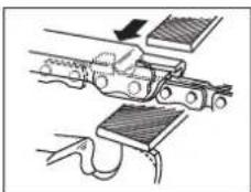
natural_image
Mechanical assembly diagram showing a lever mechanism with no visible text or symbols25 26
text_image
Labeled diagram of a chain drive with numbered parts for identificationtext_image
Diagram of a car interior with labeled parts A, B, C, and D indicating different components or parts.Abb. 4B
text_image
Diagram showing a hand using a chainsaw to cut a dark object labeled 'D', likely illustrating a mechanical or electrical process.5

natural_image
Three black-and-white icons: a fuel pump, a plus sign with droplets, and a car with a droplet (no text or symbols)natural_image
Close-up of a mechanical tool with labeled component A (no readable text or symbols)18A
natural_image
Close-up of a mechanical device with labeled parts B and C, showing internal components and wiring (no readable text or symbols beyond labels)18B
YAKIT FILTRESI

natural_image
Close-up of a mechanical component with a tool and labeled point A (no readable text or symbols)19
KIVILCIM KAFESİ (Şekil 20A)
natural_image
Close-up of a mechanical component with labeled point A (no readable text or symbols)21A
text_image
C B21B
KARBÜRATÖR AYARI
natural_image
Close-up of a mechanical component with a hand holding a tool, no visible text or symbols22
TESTERENİN YENİDEN KULLANIMA ALINMASI
natural_image
Illustration of hands using a tool to adjust or install a mechanical component (no text or symbols visible)23
PALANIN BAKIMI:
text_image
85° 60° 0.65mm (0.025°)24

text_image
Technical diagram showing hand tooling with labeled components and angle measurement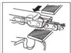
natural_image
Mechanical assembly diagram showing a tool interacting with a bracket and clamped parts (no text or symbols)25 26
PALA
X 2000/14/EG: L_WM = 110 dB; L_WA = 114 dB P = 1.7 kW
x 89/336/EWG_93/68/EEC
95/54/EG:
90/396/EWG
X 97/68/EG: e4*97/68SH2G3*2002/88*0112*00
89/686/EWG
EN ISO 11681-1; EN ISO 14982; CISPR 12; KBV V TÜV Rheinland Product Safety GmbH, Am Grauen Stein, D-51105 Köln BM 60010628
Subject to change without notice
GB WARRANTY CERTIFICATE
The product described in these instructions comes with a 5 year warranty covering defects. This 5-year warranty period begins with the passing of risk or when the customer receives the product.
For warranty claims to be accepted, the product has to receive the correct maintenance and be put to the proper use as described in the operating instructions.
Your statutory rights of warranty are naturally unaffected during these 5 years.
This warranty applies in Germany, or in the respective country of the manufacturer's main regional sales partner, as a supplement to local regulations. Please note the details for contacting the customer service center responsible for your region or the service address listed below.
© CERTIFICADO DE GARANTIA
Eschenstraße 6 · D-94405 Landau/Isar (Germany)
Info-Tel. 0180-5 120 509 • Telefax 0180-5 835 830
The reprinting or reproduction by any other means, in whole or in part, of documentation and papers accompanying products is permitted only with the express consent of ISC GmbH.