
Automower EPOS Plugin Kit - Robotic mower HUSQVARNA - Free user manual and instructions
Find the device manual for free Automower EPOS Plugin Kit HUSQVARNA in PDF.
| Product Type | EPOS extension kit for robotic lawnmower |
| Brand | Husqvarna |
| Compatible models | Automower 320/430X/450X NERA |
| Reference station dimensions (L x W x H) | 36 x 19 x 36 cm |
| Reference station weight | 0.88 kg |
| Arm weight | 0.33 kg |
| Power supply - input | 100-240 V AC, 50-60 Hz |
| Power supply - output | 28 V DC, 1.3 A |
| Low voltage cable length | 20 m |
| Station protection rating | IPX5 |
| Power supply protection rating | IP44 |
| Power consumption | 2 W |
| Radio frequency bands | Bluetooth 2.4 GHz, SRD 868/915 MHz |
| Maximum range station-reference / mower | 500 m (clear line of sight) |
| Operating temperature | -20 °C to 45 °C |
| Storage temperature | -20 °C to 70 °C |
| Minimum installation height of station | 2 m |
| Max. number of reference points per zone | 800 |
| Max. total number of reference points | 1000 |
| Maximum operating slope | 50 % |
| Warranty | 2 years |
| Maintenance | Clean with a damp cloth; annual check of installation |
| Safety | Mandatory use of a residual current device (RCD); disconnect before maintenance |
| Kit contents | Reference station, arm, mounting brackets, EPOS plug-in, screws, washers, 36 V power supply, low voltage cable, manual |
Frequently Asked Questions - Automower EPOS Plugin Kit HUSQVARNA
User questions about Automower EPOS Plugin Kit HUSQVARNA
0 question about this device. Answer the ones you know or ask your own.
Ask a new question about this device
Download the instructions for your Robotic mower in PDF format for free! Find your manual Automower EPOS Plugin Kit - HUSQVARNA and take your electronic device back in hand. On this page are published all the documents necessary for the use of your device. Automower EPOS Plugin Kit by HUSQVARNA.
USER MANUAL Automower EPOS Plugin Kit HUSQVARNA
flowchart
graph TD
    A["A"] --> B["B"]
    B --> C["C"]
    C --> A
    style A fill:#f9f,stroke:#333
    style B fill:#ccf,stroke:#333
    style C fill:#cfc,stroke:#333
natural_image
Simple line drawing of a person sitting on a chair under a dashed circular boundary (no text or symbols)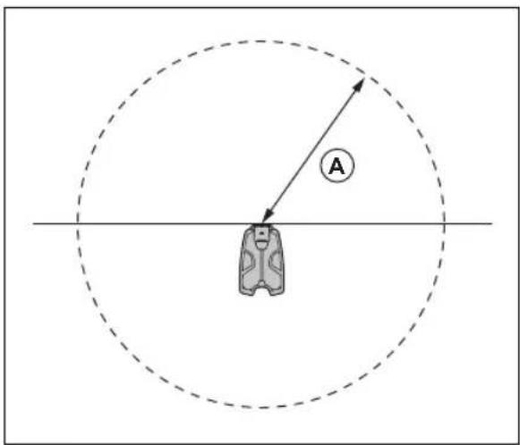
natural_image
Technical line drawing of a robotic vacuum cleaner (no text or symbols)natural_image
Technical line drawing of a car engine compartment with mounting points and a highlighted component (no text or symbols)natural_image
Technical diagram showing engine compartment assembly with valve and housing (no text or labels)- Installera EPOS Plug-in med fyra skruvar.
- Installera toppkåpan.
3.10.3 Göra EPOS™ -konfigurationen
natural_image
Technical line drawing of a mechanical component with a downward arrow indicating assembly or force (no text or symbols present)natural_image
Technical line drawing of a car airbag with cable and connector (no text or symbols)natural_image
Technical line drawing of a mechanical component with an arrow indicating a process or assembly (no text or symbols present)natural_image
Technical illustration of a mechanical device mounted on a vertical post, showing front and side views (no text or symbols)natural_image
Technical line drawing of a mechanical component with directional arrows indicating movement or flow (no text or symbols present)natural_image
Mechanical assembly diagram showing a mechanical component with a shaft and housing, plus an inset view of a mechanical component (no text or labels)natural_image
Technical diagram showing mechanical assembly with a lever and directional arrow (no text or symbols)natural_image
Technical line drawing of a mechanical component with a labeled inset showing 'T20' (no other text or symbols)natural_image
Technical line drawing of a mechanical assembly with exploded view (no text or symbols)natural_image
Technical line drawing of a mechanical component with a cylindrical base and downward arrow indicating force or motion (no text or symbols)natural_image
Technical line drawing of a mechanical component with pins and mounting holes (no text or symbols)natural_image
Technical diagram of a mechanical assembly with an inset showing a close-up of a component detail (no text or symbols present)natural_image
Technical diagram showing mechanical assembly with directional arrows and component details (no text or symbols)
natural_image
Simple line drawing of a car door with a location pin (no text or symbols)natural_image
Simple line drawing of a vehicle or container with a location pin and an arrow pointing to it (no text or symbols)natural_image
Diagram showing a backpack and location pin with directional arrows, no text or symbols presentnatural_image
Diagram showing a hexagonal shape with internal patterns and a backpack icon, no text or symbols present.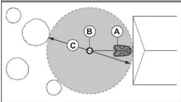
flowchart
graph TD
    A["A"] --> B["B"]
    B --> C["C"]
    C --> A
    style A fill:#f9f,stroke:#333
    style B fill:#ccf,stroke:#333
    style C fill:#cfc,stroke:#333
natural_image
Simple line drawing of a person standing at the center of a circular target with dashed lines (no text or symbols)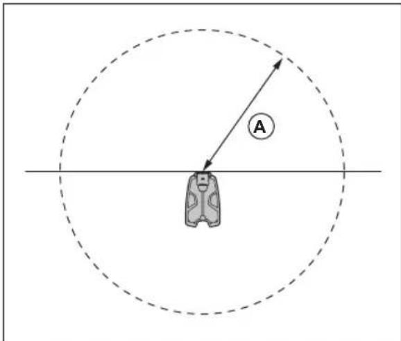
natural_image
Technical line drawing of a robotic lawn mower (no text or symbols)natural_image
Technical line drawing of a car engine compartment with mounting points and a directional arrow (no text or symbols)natural_image
Technical diagram showing mechanical assembly with arrows indicating assembly steps (no text or labels present)natural_image
Technical line drawing of a mechanical component with a downward arrow indicating assembly or force (no text or symbols present)natural_image
Technical line drawing of a mechanical device with internal wiring and a labeled component (no readable text or symbols)natural_image
Technical line drawing of a mechanical component with an arrow indicating direction (no text or symbols)natural_image
Technical illustration of a mechanical device mounted on a vertical post, showing assembly and mounting detail (no text or symbols)natural_image
Technical line drawing of a mechanical component with directional arrows indicating movement or flow (no text or symbols present)natural_image
Technical diagram of a mechanical assembly with a component and a close-up inset showing internal components (no text or labels)natural_image
Technical diagram showing mechanical assembly with a lever and directional arrow (no text or symbols)natural_image
Technical line drawing of a mechanical component with a labeled inset showing 'T20' (no text or symbols on the diagram itself)natural_image
Exploded view diagram of a mechanical assembly with bolted components (no text or labels)natural_image
Technical line drawing of a mechanical component with a cylindrical base and downward arrow indicating force or movement (no text or symbols)natural_image
Technical line drawing of a mechanical component with pins and connectors (no text or symbols)natural_image
Technical diagram of a mechanical assembly with a component inserted into a housing, showing internal components and motion arrows (no text or labels)natural_image
Technical diagram showing mechanical assembly with a lever and directional arrow (no text or symbols)
natural_image
Simple line drawing of a car hood with a location pin (no text or symbols)natural_image
Simple line drawing of a vehicle or road sign with a location pin and an arrow (no text or symbols)natural_image
Diagram showing a backpack with location pin and directional arrow, no text or symbols presentflowchart
graph TD
    A["Hexagon with jagged edges and scattered points"] --> B["Backpack icon"]
    style A fill:#f9f,stroke:#333
    style B fill:#bbf,stroke:#333
Sådan oprettes en transportsti
flowchart
graph TD
    A["A"] --> B["B"]
    B --> C["C"]
    C --> D["3D Shape"]
    style A fill:#f9f,stroke:#333
    style B fill:#ccf,stroke:#333
    style C fill:#cfc,stroke:#333
natural_image
Simple line drawing of a person sitting on a bench under a dashed circular threshold (no text or symbols)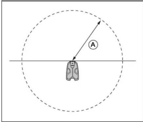
natural_image
Technical line drawing of a robotic lawn mower (no text or symbols)natural_image
Technical line drawing of a car interior with mounting brackets and a highlighted component (no text or symbols)natural_image
Technical diagram showing mechanical assembly with arrows indicating assembly steps (no text or symbols present)natural_image
Technical line drawing of a mechanical component with a downward arrow indicating assembly or force (no text or symbols present)natural_image
Technical line drawing of a mechanical device with visible wiring and components (no text or symbols)natural_image
Technical line drawing of a mechanical component with an arrow indicating direction (no text or symbols)natural_image
Technical illustration of a mechanical clamp or sensor assembly with a dashed line indicating water level (no text or symbols present)natural_image
Technical line drawing of a mechanical component with directional arrows indicating movement or flow (no text or symbols present)natural_image
Technical diagram of a mechanical assembly with an inset showing a close-up of a component detail (no text or symbols present)natural_image
Technical diagram showing mechanical assembly with a lever and directional arrow (no text or symbols)natural_image
Technical line drawing of a mechanical housing assembly with bolted components (no text or labels)natural_image
Technical line drawing of a mechanical component with a cylindrical base and downward arrow indicating force or motion (no text or symbols)natural_image
Technical line drawing of a mechanical component with pins and mounting holes (no text or symbols)natural_image
Mechanical assembly diagram showing a lever mechanism with a close-up inset of the component detail (no text or labels)natural_image
Technical diagram showing mechanical assembly with a lever and directional arrow (no text or symbols)
natural_image
Simple line drawing of a car with a location pin (no text or symbols)natural_image
Simple line drawing of a vehicle or container with a location pin and an arrow pointing to it (no text or symbols)natural_image
Diagram showing a backpack with a location pin and directional arrow, no text or symbols present- Referansestasjon
- Arm
- Støttebrakett
- Liten stolpebrakett, for stolpemål 32-44 mm/1.26-1.73 tommer
- Stor stolpebrakett, for stolpemål 44-55 mm/44-55 tommer
-
Automower ® EPOS™ Plug-in
-
Skruer
- Skruer
- Skiver
- Strømforsyning 22
- Lavspenningskabel
- Bruksanvisning
29.1.5 Systemoversikt
- Hvis robotklipperen ikke kan brukes i en del av dokkingområdet, må du sette opp en beskyttelsesvegg som er minst 15 cm / 6 tommer høy. Dokkingområdet (A) er et sirkulært område rundt ladestasjonen med en radius på 3 m / 9.8 fot.
natural_image
Simple line drawing of a person in a suit standing near a horizontal line with a shaded band, enclosed by a dashed circle (no text or symbols)
- Plasser strømforsyningen i et område med tak over og beskyttelse mot sol og regn.
- Plasser strømforsyningen i et område med god luftsirkulasjon.
- Bruk en reststrømenhet (RCD) med en strømutløsning på maksimalt 30 mA når du kobler strømforsyningen til strømuttaket.
- For skräninger like ved en offentlig vei må du plassere et gjerde eller en beskyttelsesvegg langs ytterkanten av skräningen.
natural_image
Technical line drawing of a robotic lawn mower (no text or symbols)natural_image
Technical line drawing of a car interior with overhead-mounted sensors and a mounted component (no text or symbols)natural_image
Technical diagram showing engine compartment assembly with tool and valve (no text or labels)- Installer EPOS-plugin-modulen med 4 skruer.
- Monter toppdekselet.
natural_image
Technical line drawing of a mechanical component with a downward arrow indicating a feature (no text or symbols present)natural_image
Line drawing of a car airbag with attached components and cable routing (no text or symbols)-
Koble lavspenningskabelen til ladestasjonen.
-
Lukk luken foran på ladestasjonen.
-
Plasser strømforsyningen i en minstehøyde på 30 cm / 12 tommer.
natural_image
Technical line drawing of a mechanical component with an arrow indicating a directional change (no text or symbols present)- Hvis indikatorlampen ikke har et grønt lys, utfører du en kontroll av installasjonen. Se Slik kontrollerer du ladestasjonen visuelt på side 88 og Slik kontrollerer du ladestasjonen visuelt på side 88.
natural_image
Technical illustration of a mechanical clamp or sensor assembly with a vertical post and side view (no text or symbols)natural_image
Technical line drawing of a mechanical component with directional arrows indicating movement or flow (no text or symbols present)natural_image
Mechanical assembly diagram showing a lever mechanism with a close-up inset of the component detail (no text or labels)- Fest kontakten til klipsene på armen.
natural_image
Technical diagram showing mechanical assembly with a lever and directional arrow (no text or symbols)natural_image
Technical line drawing of a mechanical component with a labeled inset showing 'T20' (no other text or symbols)natural_image
Technical line drawing of a mechanical housing assembly with bolted components (no text or labels)natural_image
Technical line drawing of a mechanical component with a cylindrical base and downward arrow indicating force or motion (no text or symbols)natural_image
Technical line drawing of a mechanical component with pins and connectors (no text or symbols)natural_image
Technical diagram of a mechanical assembly with a component inserted into a housing, showing internal components and motion arrows (no text or labels)- Fest kontakten til klipsene på armen.
natural_image
Technical diagram showing mechanical assembly with a lever and directional arrow (no text or symbols)
natural_image
Simple line drawing of a car hood with a location pin, no text or symbols presentMerk: Når du installerer en transportvei eller en vei til et vedlikeholdspunkt, er posisjonen til veipunktet midt på robotklipperen.
natural_image
Simple line drawing of a vehicle or container with a location pin and an arrow pointing to it (no text or symbols)flowchart
graph TD
    A["Container"] --> B["Bag"]
    B --> C["Wall with Brick Wall"]
    C --> D["Arrow to Bag"]
    D --> E["Arrow to Box"]
natural_image
Diagram showing a backpack with a location pin and directional arrow, no text or symbols presentflowchart
graph TD
    A["Hexagon with jagged edges and scattered points"] --> B["Backpack icon"]
    B --> C["Arrow indicating direction"]
    style A fill:#f9f,stroke:#333
    style B fill:#ccf,stroke:#333
Hvordan du oppretter en transportvei
Slik installerer du ladestasjonen på nytt på kartet Installer ladestasjonen på nytt på kartet hvis du flytter eller bytter ladestasjonen. Du kan også installere den på nytt hvis robotgressklipperen ikke kan dokke eller kobles til ladestasjonen.
42 Storage and disposal....124
43 Technical data.... 124
44 Warranty....125
45 Declaration of Conformity....126
37 Safety
37.1 Safety definitions
Warnings, cautions and notes are used to point out specially important parts of the manual.

WARNING: Used if there is a risk of injury or death for the operator or bystanders if the instructions in the manual are not obeyed.

CAUTION: Used if there is a risk of damage to the product, other materials or the adjacent area if the instructions in the manual are not obeyed.
Note: Used to give more information that is necessary in a given situation.
37.2 General safety instructions

WARNING: Read the warning instructions that follow before you use the product.
- Obey national regulations about electrical safety.
- The product is only to be used with the power supply unit supplied by Husqvarna.
- The product may only be used with the equipment recommended by the manufacturer. All other types of use are incorrect. The manufacturer's instructions with regard to operation/maintenance must be followed precisely.
- The product may only be operated, maintained and repaired by persons that are fully conversant with its special characteristics and safety regulations. Please read the Operator's Manual carefully and make sure you understand the instructions before using the product.
- Husqvarna does not guarantee full compatibility between the product and other types of
wireless systems such as remote controls, radio transmitters, hearing loops, underground electric animal fencing or similar.
- It is not permitted to modify the original design of the product. All modifications are made at your own risk.
- The operating temperature is -20ircC to 45ircC / -4ircF to 113ircF . The storage temperature is -20ircC to 70ircC / -4ircF to 158ircF .
37.3 Safety instructions for installation

WARNING: Read the warning instructions that follow before you use the product.
- Do not put the power supply at a position where there is a risk that it can become wet. Do not put the power supply on the ground.
- Do not encapsulate the power supply. Condensed water can harm the power supply and increase the risk of electrical shock.
- Risk of Electric Shock. Install only to an residual-current device (RCD) when connecting the power supply to the wall socket. Applicable to USA/Canada. If power supply is installed outdoors: Risk of Electric Shock. Install only to a covered Class A GFCI receptacle (RCD) that has an enclosure that is weatherproof with the attachment plug cap inserted or removed.
- Make sure that the plugs of the low-voltage cable and the power supply unit are clean and dry before you connect them.
- There is a risk of falling objects during the installation of the reference station. This can result in injury.
- The power supply cable and extension cable must be outside the work area to prevent damage to the cables.
- There is a risk of falling when you install the reference station in a high position. Make sure that you have a stable position when you install the reference station.
37.4 Safety instructions for maintenance

WARNING: Read the warning instructions that follow before you use the product.
- Disconnect the product from the power supply before you clean or do maintenance on the product.
37.5 In the event of a thunderstorm
To decrease the risk of damage to electrical components in the reference station, we recommend that the power supply to the reference station is disconnected if there is a risk of a thunderstorm. Connect the power supply again when there is no a risk of thunderstorm.
38 Introduction
38.1 Introduction
| Serial number: | |
| Product number: |
The serial number is on the product rating plate and on the product carton. Use the serial number to register your product on www.husqvarna.com.
38.1.1 Support
For support about the product, speak to your Husqvarna servicing dealer.
38.1.2 Product description
Note: Husqvarna regularly updates the appearance and function of the products. Refer to Support on page 103
This kit includes an EPOS ™ reference station and a EPOS ™ Plug-in to be installed on your 320/430X/450X NERA robotic lawn mower. The EPOS ™ reference
station receives satellite signals and sends correction data to the robotic lawn mower. The EPOS™ Plug-in use satellite signals and the correction data from the reference station for positioning.
38.1.3 System description
The EPOS ™ system contains a robotic lawn mower, a charging station and a reference station. The robotic lawn mower and the reference station receives satellite signals for positioning. The reference station is stationary and sends correction data to the robotic lawn mower to get an accurate position for the mower. The work area is made virtually in an app by operating the product and adding waypoints to make a map in an app.
38.1.4 Product overview
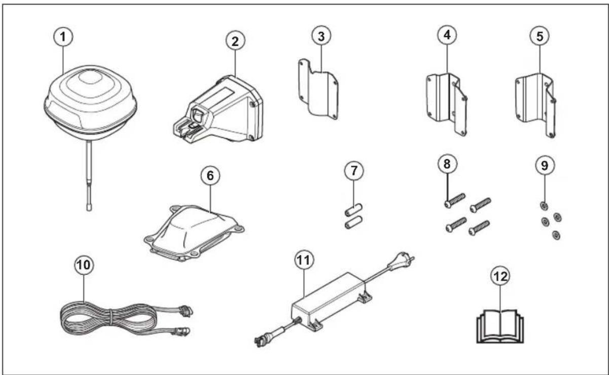
- Reference station
- Arm
- Support bracket
- Post bracket small, for post dimensions 32-44 mm/1.26-1.73 in.
- Post bracket large, for post dimensions 44-55 mm/44-55 in.
-
Automower ® EPOS™ Plug-in
-
Screws
- Screws
- Washers
- Power supply 29
- Low-voltage cable
- Operator's manual
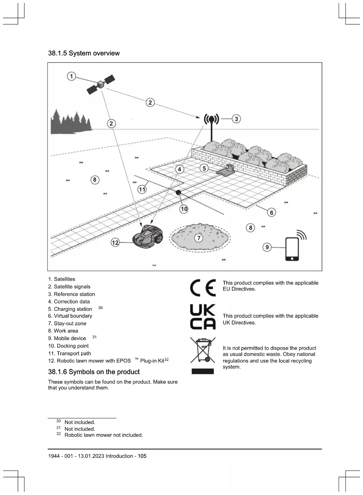
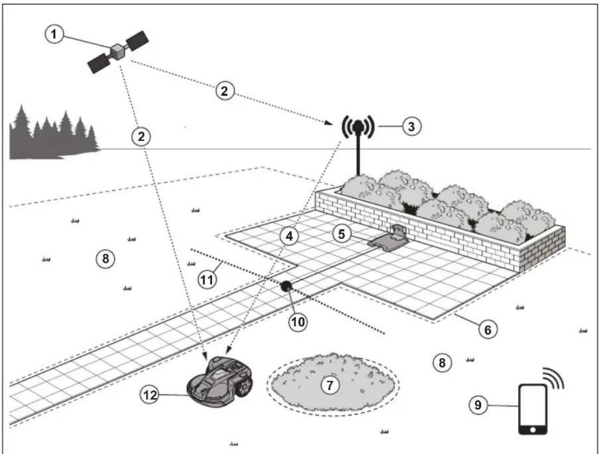
38.1.5 System overview
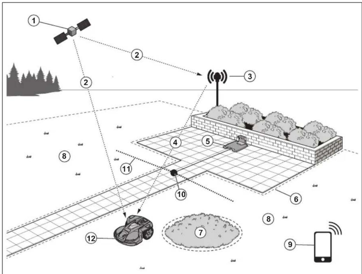
- Satellites
- Satellite signals
- Reference station
- Correction data
- Charging station 30
- Virtual boundary
- Stay-out zone
- Work area
- Mobile device 31
- Docking point
- Transport path
- Robotic lawn mower with EPOS TM Plug-in Kit 32
38.1.6 Symbols on the product
These symbols can be found on the product. Make sure that you understand them.

This product complies with the applicable EU Directives.

This product complies with the applicable UK Directives.
It is not permitted to dispose the product as usual domestic waste. Obey national regulations and use the local recycling system.
Use a detachable power supply as specified on the rating plate adjacent to the symbol.
The chassis contains components which are sensitive to electrostatic discharge (ESD). The chassis must only be opened and sealed by an authorized service technician. The warranty will not be applicable if the seal is broken.
Note: Other symbols/decals on the product refer to certification requirements for some markets.
38.1.7 Symbols in the app

Shows the strength of the radio signal that the product receives from the reference station.

The status is EPOS confirmed. The product has an accurate position and direction. This is necessary to operate the product automatically and for the installation of map objects.

The status is EPOS action is necessary. The product has an accurate position but it is necessary to operate the product, manually or automatically, to get an accurate direction.

The status is EPOS searching. The product does not have an accurate position and is searching for the satellite signals and the correction data to get an accurate position.
39 Installation
39.1 Introduction - Installation

WARNING: Read and understand the safety chapter before you install the product.

WARNING: Read and understand the safety chapter in the manual for the robotic lawn mower before you install the product.

CAUTION: Use original spare parts and installation material.
Note: Refer to www.husqvarna.com for more information about installation.
39.2 Primary components for installation
The installation includes the components that follow:
- Robotic lawn mower automatically.
33 , that cuts the lawn
- Charging station
34 , that charges the product.
• Power supply unit 35 , which is connected to the charging station and a 100-240V power outlet.
- Power supply unit, which is connected to the reference station and a 100-240V power outlet.
- Reference station, that receives satellite signals and sends correction data to the robotic lawn mower.
- Automower EPOS TM Plug-in.
- Mobile device with the Automower Connect app to do the installation and the settings for the product.
39.3 To prepare for installation

CAUTION: Holes with water in the lawn can cause damage to the product.

CAUTION: Read the installation chapter before you start the installation.
- Make a blueprint of the work area and include all obstacles. This makes it easier to examine where to put the charging station, the reference station, and the virtual boundaries.
• Make a mark on the blueprint where to put the charging station, the reference station, the maintenance point, the transport paths and the virtual boundaries for the work areas and stay-out zones.
- Follow the instructions for distances between obscuring objects.
- Fill in holes in the lawn to make it level.
- Cut the grass before you install the product. Make sure that the grass is maximum 10 cm / 4 in.
Note: The first weeks after installation the sound level when the product cuts the grass can be higher than usual. The sound level decreases after some time.
39.4 To examine where to put the reference station

CAUTION: If there is a lightning rod near by, do not install the reference station higher than the lightning rod.

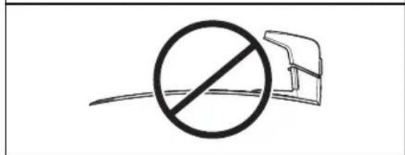
CAUTION: Do not install the reference station on a flagpole. Movements of the reference station will affect the correction data sent to the product with the accurate position.
• Install the reference station on a fixed object that cannot move or rotate.
• Install the reference station on a post or a wall. The post must be 32-55 mm / 1.26-2.16 in. in diameter to fit the attachments on the reference station.
Note: If the reference station is installed on a wall the top of the reference station must be above the wall. Metal objects can cause interference with the reference station signal.
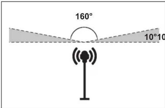
- Make sure that the reference station has full view of the sky. It is necessary that minimum 135 degrees of the sky has a full view. We recommend that the sky has a full view in all directions more than 10irc in elevation angle.
• Install the reference station at minimum 2 m / 6.5 ft. height.
• The maximum distance between the reference station and the product is 500 m / 1640 ft. when free line of view. Objects between the reference station and product decreases the distance.
39.5 To examine where to put the power supply
- Put the power supply in an area with a roof and protection from the sun and rain.
- Put the power supply in an area with good airflow.
- Use a residual-current device (RCD) when you connect the power supply to the power outlet.
- Extend the low-voltage cable if necessary. The low-voltage cable can be extended up to 100 m / 328 ft.
39.6 To examine where to put the charging station
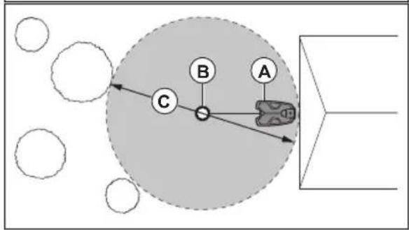
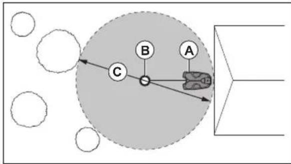
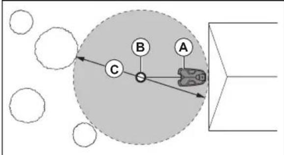
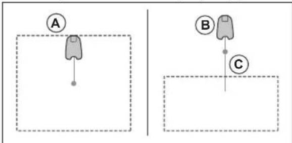
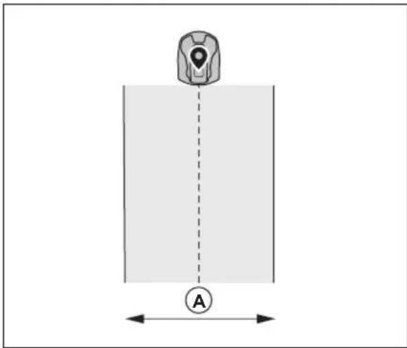
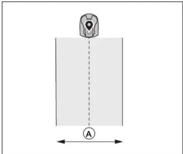
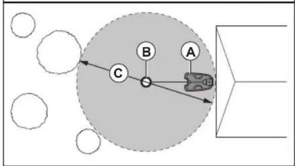
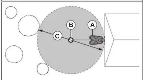
- You can put the charging station in the work area or not in the work area. No transport path is necessary if the charging station is put in the work area (A). No transport path is necessary if the product is fully in the work area when it is at the charging station docking point. If the charging station and docking point (B) are not in the work area, you must install a transport path (C).
- You can put the charging station in an Automower® house.
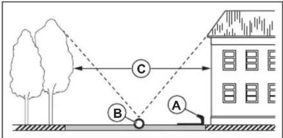
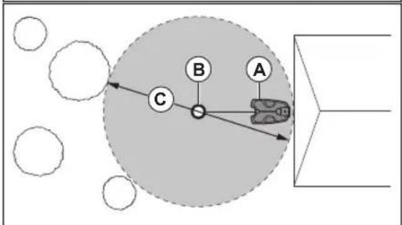
- Put the charging station (A) where the docking point (B) has unimpeded sky view. The charging station docking point (B) is where the product
stops after reversing from the charging station.
The reversing distance can be set to 70-250 cm / 28-98 in. Make sure that there is minimum 3 m (C) between objects that are higher than 1 m / 3.3 ft. around the docking point (B).
flowchart
graph TD
    A["A"] --> B["B"]
    B --> C["C"]
    C --> A
    style A fill:#f9f,stroke:#333
    style B fill:#ccf,stroke:#333
    style C fill:#cfc,stroke:#333
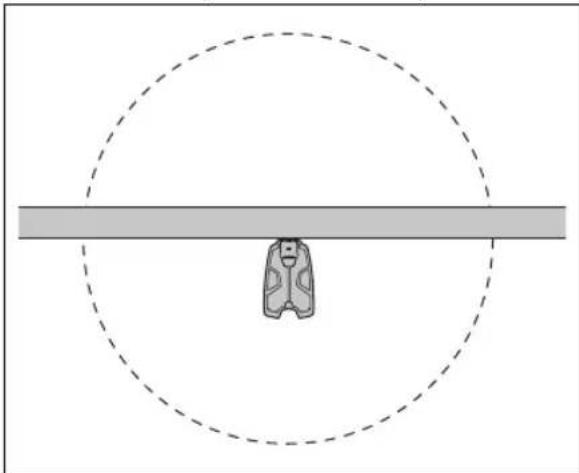
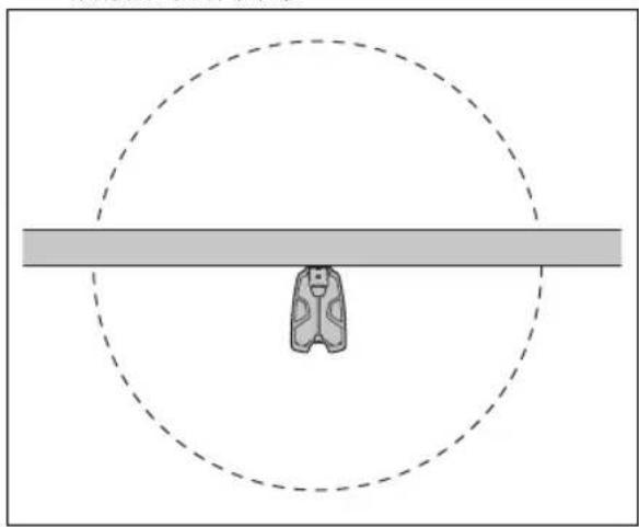
- If the product must not operate in a part of the docking area, put a protective wall that is minimum 15 cm / 6 in. in height. The docking area (A) is a circular area around the charging station with a radius of 3 m / 9.8 ft.
natural_image
Simple line drawing of a person sitting on a bench under a dashed circular threshold (no text or symbols)
Note: The product uses the charging station signal to search for the charging station when it is in the docking area.
- Put the charging station near a power outlet.
- Put the charging station on a level surface.
- The baseplate of the charging station must not be bent.
- If the work area has 2 parts separated with a steep slope, Husqvarna recommends to put the charging station in the lower section.

CAUTION: Do not install the charging station where there are metal objects in the ground. Metal objects can cause interference with the charging station signal.
39.7 To examine where to put the power supply

CAUTION: Make sure that the blades on the product do not cut the low-voltage cable.

CAUTION: Do not put the low-voltage cable in a coil or below the charging station plate. The coil causes interference with the signal from the charging station.
- Put the power supply in an area with a roof and protection from the sun and rain.
- Put the power supply in an area with good airflow.
- Use a residual-current device (RCD) with a tripping current of maximum 30 mA when you connect the power supply to the power outlet.
Low-voltage cables of different lengths are available as accessories.
39.8 To examine where to install the virtual boundaries

CAUTION: If the work area is adjacent to water bodies, slopes, precipices or a public road, there must be a protective wall. The wall must be minimum 15 cm / 6 in. in height.

CAUTION: Do not let the product operate on gravel.
- For careful operation without noise, isolate all obstacles such as trees, roots and stones.
- Make a blueprint of the work area before you install the virtual boundaries.
39.9 To install map objects near buildings and trees
When the product operates it must have unimpeded sky view to use the satellite signals for navigation.
- Make sure that 90irc section of the sky is unimpeded.
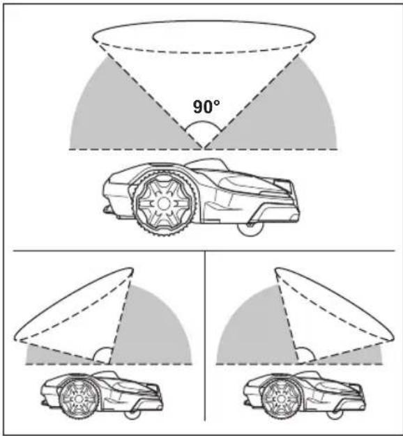
Note: Objects that are less than 1 m / 3.3 ft. in height does not interfere with the operation of the product.
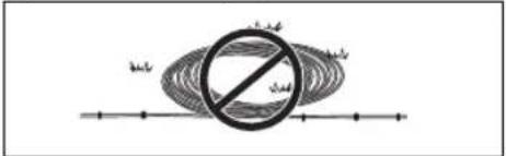
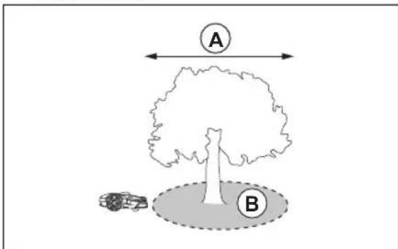
Note: Tree canopies that are less than 4 m / 13 ft. in diameter does not interfere with the operation of the product. If there are many small trees put together in an area, if the diameter of their canopies put together is less than 4 m / 13 ft. they do not interfere with the operation of the product.
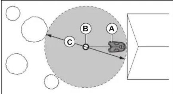
- For trees with tree canopies that is more than 4 m / 13 ft. in diameter (A), make a stay-out zone (B) around the trees.
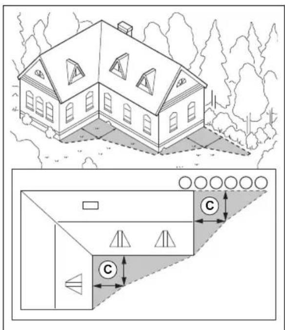
- For L-shaped objects higher than 1 m / 3.3 ft, install the virtual boundary at a minimum distance (C) of 1.5 m / 5 ft. from it.
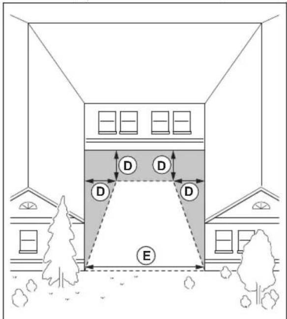
- To install virtual boundaries in an area with an U-shaped object higher than 1 m / 3.3 ft, make sure that the distance (E) is minimum 6 m / 20 ft. If the object is higher than 3 m / 10 ft., make sure that the distance (E) is twice the height of the highest object. Install the virtual boundary at a minimum distance (D) of 1.5 m / 5 ft. from the object.
- For areas between objects higher than 1 m / 3.3 ft. the distance (F) must be minimum 4 m / 13 ft.
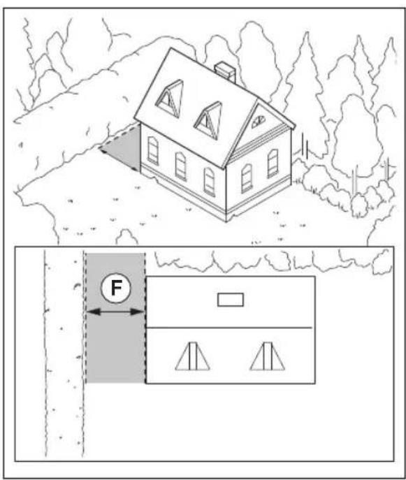
Note: For areas with a width less than 4 m / 13 ft. a transport path can be made for the robotic lawn mower to go through without cutting.
39.9.1 Passages
A passage is a section that has virtual boundary on each side and that connects 2 parts of the work area. The passage must be a minimum of 2 m / 6.5 ft. wide to get a good cutting result.
39.9.2 To install the map objects in a slope
The product can operate in 50% slopes. Do not include too steep slopes in the work area. Too steep slopes can be isolated as stay-out zones. The slope (%) is calculated as height for each m. Example: 10 cm / 100 cm = 10%.
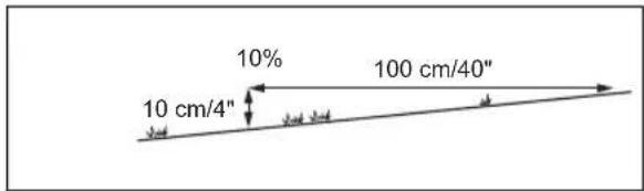
- For slopes more than 50% in the work area, isolate the slope with a stay-out zone.
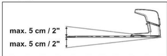
- For slopes that are more than 25% along the outer edge of the lawn. For installation of the virtual boundary, operate the product with the rear wheel 5 cm / 2 in . (A) from the edge.
- For slopes adjacent to a public road, put a fence or a protective wall along the outer edge of the slope.
39.10 To install the product
- Install the EPOS TM Plug-in. Refer to To install the EPOS plug-in on page 111.
- Install the Automower ® Connect app on your mobile device. Refer to Automower ® Connect on page 112.
- Do a pairing operation of the product and the Automower® Connect app. Do the EPOS™ setup in the Automower® Connect app. Refer to To do the EPOS™ setup on page 111.
- Install the charging station. Refer to To install the charging station on page 112.
- Install the reference station. Refer to Installation of the reference station on page 113
- Make a map with work areas, stay-out zones, transport paths and maintenance points. Refer to Installation of the map objects on page 116.
- Use Automower ® Connect app to do settings for the product. Refer to Automower ® Connect on page 112.
Note: For more information about settings in the app, read the Operator's manual for the robotic lawn mower.
39.10.1 Installation tools
- Screwdriver, Torx 20.
• Hex key, 4 mm. Included in the carton.
• Hex key, 8 mm. Included in the carton.
39.10.2 To install the EPOS plug-in
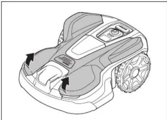
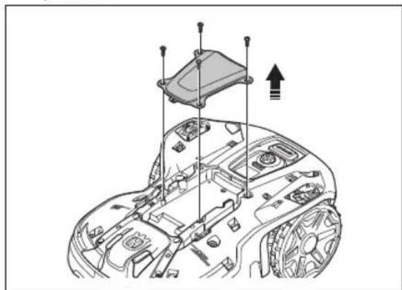
- Remove the top cover on the robotic lawn mower.
natural_image
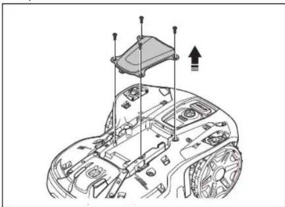
Technical line drawing of a robotic lawn mower (no text or symbols)- Remove the 4 screws (Torx20) and the cover plate.
natural_image
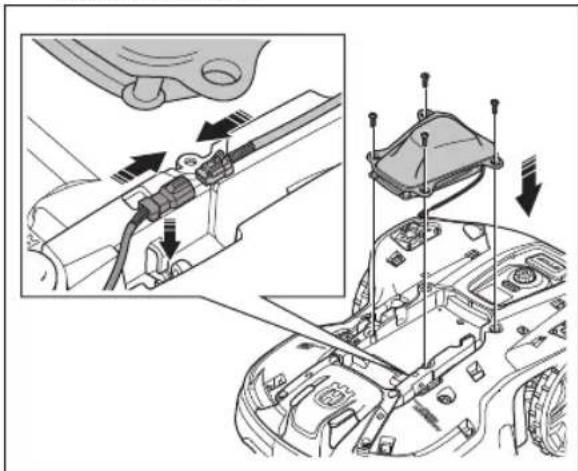
Technical line drawing of a car interior with mounting brackets and a component labeled 'Top Cover' (no text or symbols present)- Remove the sealing plug on the connector.
- Connect the cable from the EPOS plug-in to the robotic lawn mower.
natural_image
Technical diagram showing engine compartment assembly with tool and valve details (no text or symbols)- Install the EPOS plug-in with 4 screws.
- Install the top cover.
39.10.3 To do the EPOS TM setup
When the product is set to ON for the first time, there are some basic settings to do before the product can
start to operate. You must do a pairing operation of the product and the Automower® Connect app to install objects on the map, change the settings and operate the product. Use the Automower® Connect app on your mobile device or on the app.
- Set the product to ON.
Note: The Bluetooth® pairing operation mode of the product is enabled for 3 minutes. If the pairing operation between the product and the mobile device is not completed in 3 minutes, set the product to OFF and then set the product to ON.
- Log on to your Husqvarna account in the Automower® Connect app.
- Start Bluetooth ® on your mobile device.
- Select My mowers in the Automower® Connect app and add your product.
- Enter the factory PIN code.
- Follow instructions for the EPOS TM setup in the Automower® Connect app. Do a paring operation with the reference station and the charging station and install the map objects.
Note: It is only necessary to do a pairing operation of the Automower® Connect app and the product one time.
39.10.4 Automower® Connect
Automower® Connect is a free app for your mobile device. Use the app for installation, settings and operation of your product. You can also find more information for example about alarm and statistics in the Automower® Connect app.
The app gives 2 modes of connectivity: Long-range cellular connectivity and Short-range Bluetooth® connectivity.
- Dashboard that shows the current status of the product and the battery state of charge.
Note: All countries do not support cellular connection to Automower® Connect because of regional specified cellular systems. The included Automower® Connect lifetime service only applies if there is a third part sub-supplier of available in the operational area.
39.10.5 Installation of the charging station
Read and understand the instructions about the charging station. Refer to To examine where to put the charging station on page 107.

CAUTION: Do not make new holes in the charging station plate.

CAUTION: Do not put your feet on the baseplate of the charging station.

WARNING: Make sure that the plugs of the low-voltage cable and the power supply unit are clean and dry before you connect them.
When you connect the power supply, only use a power outlet that is connected to a residual-current device (RCD).
39.10.5.1 To install the charging station

CAUTION: Do not make new holes in the charging station plate.

CAUTION: Do not put your feet on the baseplate of the charging station.

WARNING: Make sure that the plugs of the low-voltage cable and the power supply unit are clean and dry before you connect them.
When connecting the power supply, only use a power outlet that is connected to an residual-current (RCD) device.
- Read and understand the instructions about the charging station. Refer to To examine where to put the charging station on page 107.
- Put the charging station in the selected area.
Note: Do not attach the charging station to the ground with the screws until the guide wire is installed.
- Open the hatch on the front of the charging station.
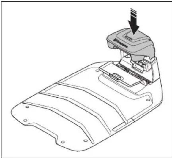
- Attach the top of the charging station.
natural_image
Technical line drawing of a mechanical component with a downward arrow indicating assembly or force (no text or symbols present)- Tilt the top of the charging station.
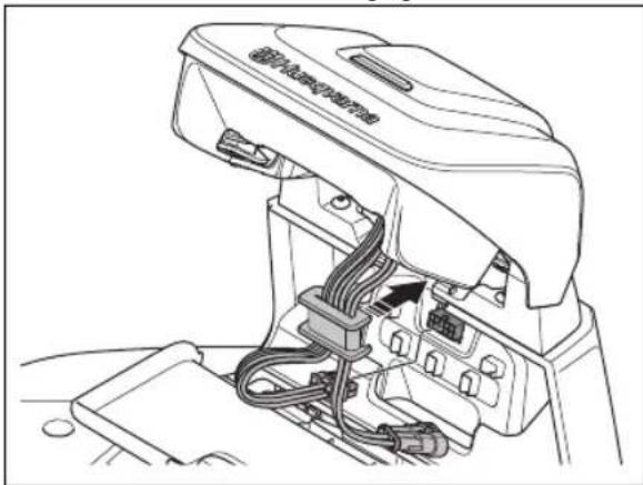
- Put the grommet with the cables into position.
- Connect the cable to the charging station.
natural_image
Technical line drawing of a mechanical device with internal wiring and housing (no text or symbols)- Connect the low-voltage cable to the charging station.
- Close the hatch on the front of the charging station.
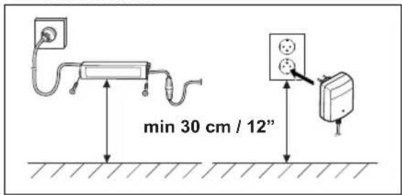
- Put the power supply at a minimum height of 30 cm / 12 in.
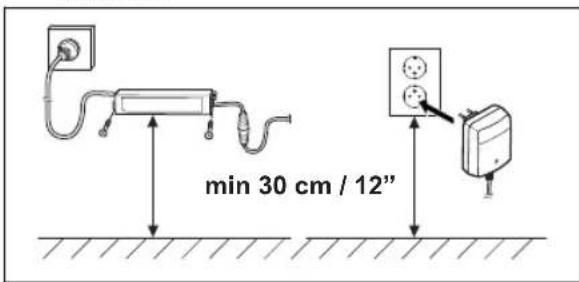
- Connect the power supply cable to a 100-240V power outlet.
Note: The product can be put in the charging station to charge while you install the boundary wire.
- Put the low-voltage cable in the ground with stakes or bury the cable.
- Connect the wires to the charging station after the installation of boundary wire and guide wire is complete.
- Attach the charging station to the ground with the supplied screws after the guide wire is installed.
39.10.5.2 To do a visual check of the charging station
- Make sure that the indicator LED lamp on the charging station has a green light.
natural_image
Technical line drawing of a mechanical component with an arrow indicating direction (no text or symbols)- If the indicator LED lamp does not have a green light, do a check of the installation. Refer to To do a visual check of the charging station on page 113 and To do a visual check of the charging station on page 113.
39.10.6 Installation of the reference station
You can install the reference station on a post or a wall.

CAUTION: Movements of the reference station will affect the correction data sent to the product with the accurate position. The reference station must be installed tightly on the post or wall.

CAUTION: The items on the map will change position if you move the reference station. Adjust the items on the map or do the installation again in the Automower® Connect app.
39.10.6.1 To install the reference station on a wall
Note: As wall materials vary, screws for fixing to the wall are not included.
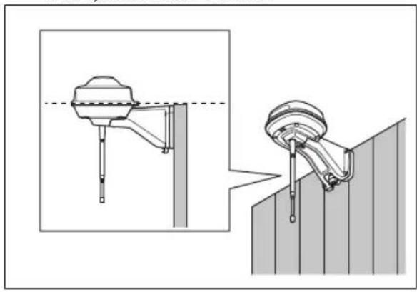
- Hold the arm for the reference station on the wall where you will attach it. Make 4 marks on the wall where you will attach 4 screws.
natural_image
Technical illustration of a mechanical device with a dashed line indicating a reference point, shown from two different angles (no text or symbols present)Note: If the reference station is installed on a wall the top of the reference station must be above the wall.
- Drill 4 holes in the wall for the 4 screws.
- Install the reference station on the wall with 4 screws.
natural_image
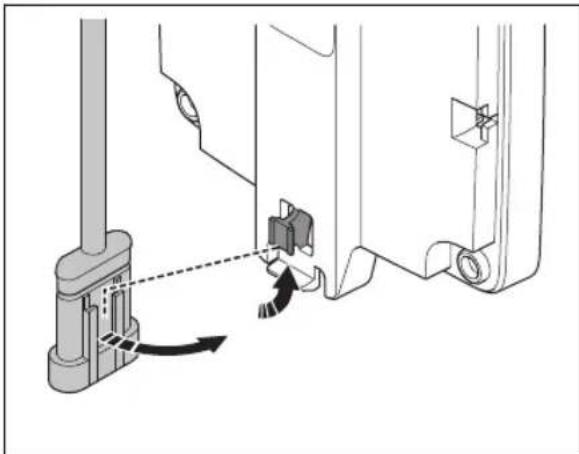
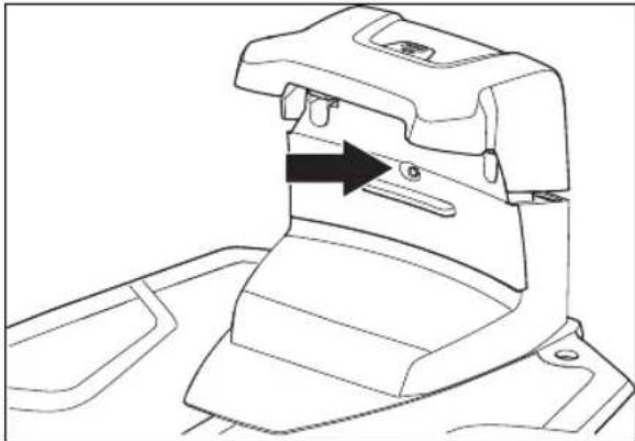
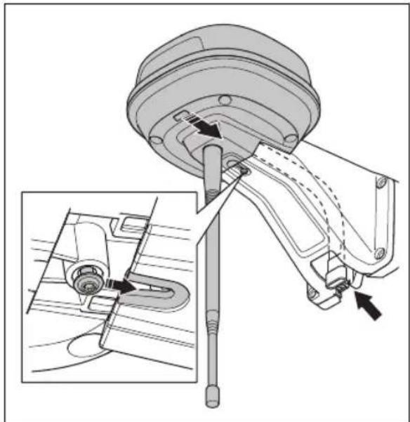
Technical line drawing of a mechanical housing component with directional arrows indicating movement (no text or symbols)- Put the cable of the reference station through the slot in the arm and install the reference station on the arm.
natural_image
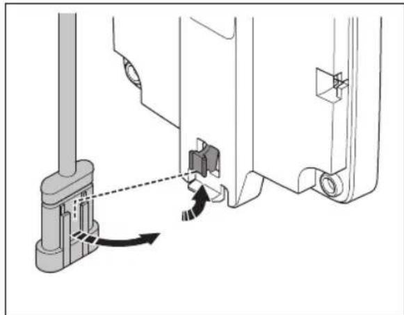
Mechanical assembly diagram showing a mechanical component with a close-up inset of its internal structure (no text or labels)- Attach the connector to the clips on the arm.

natural_image
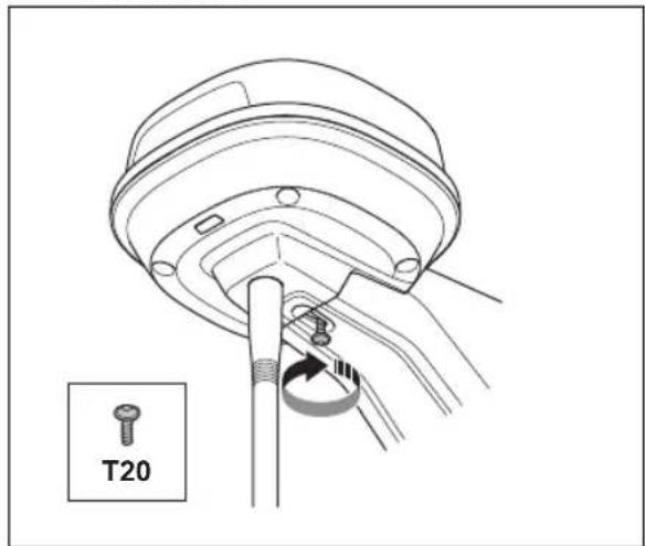
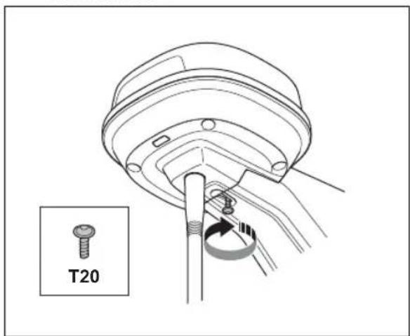
Technical diagram showing mechanical assembly with a lever and directional arrow (no text or symbols)- Tighten the screw (Torx 20) on the arm of the reference station.
-
Connect the low-voltage cable to the reference station and the power supply.
-
Attach the low-voltage cable to the wall from the reference station to the power supply with cable ties.

CAUTION: If the low-voltage cable is not attached tightly with cable ties it can be damaged in hard wind.
-
Put the power supply 30-200 cm / 1-6.5 ft. above the ground. Refer to To examine where to put the power supply on page 107.
-
Connect the power supply cable to a 100-240V power outlet.
-
Wait until the LED status indicator is solid green. First the LED status indicator flashes green for some minutes. Refer to LED indicator lamp on the reference station on page 124.
39.10.6.2 To install the reference station on a post
-
Attach the post tightly to a wall, roof top or the ground. Make sure that the post cannot move or be accidentally moved.
-
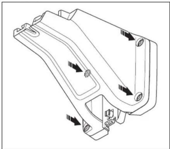
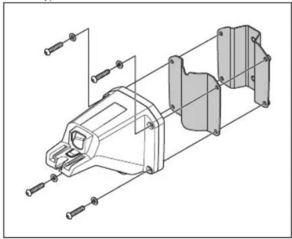
Attach the support bracket and one of the post brackets to the arm with the 4 screws (4 mm hex key).
natural_image
Technical line drawing of a mechanical assembly with exploded view (no text or symbols)Note: The post brackets are available in 2 dimensions to fit different dimensions of the post. Select the applicable post bracket for your installation.
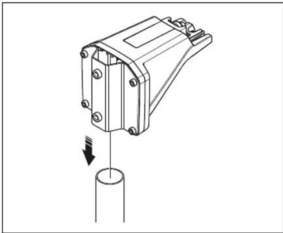
- Put the arm on top of the post.
natural_image
Technical line drawing of a mechanical component with a cylindrical base and downward arrow indicating force or motion (no text or symbols)Note: The reference station must be installed at the top of the post.
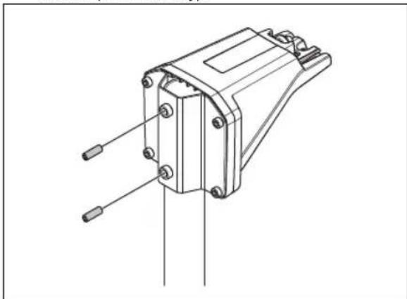
- Attach the reference station to the post with the 2 screws (4mm hex key).
natural_image
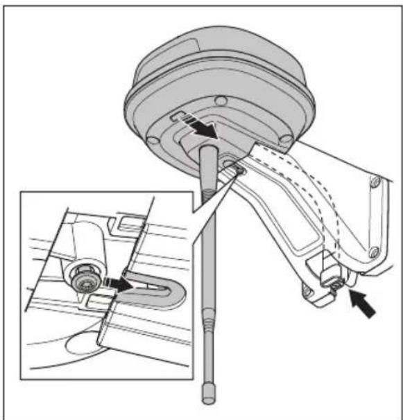
Technical line drawing of a mechanical component with pins and mounting holes (no text or symbols)- Pull the cable on the reference station through the slot in the arm and install the reference station on the arm.
natural_image
Technical diagram of a mechanical assembly with a component and close-up view (no text or labels)- Attach the connector to the clips on the arm.

natural_image
Technical diagram showing mechanical assembly with directional arrows indicating movement (no text or symbols)- Tighten the screw (Torx 20) on the arm of the reference station.
-
Connect the low-voltage cable to the reference station and the power supply. Refer to To examine where to put the power supply on page 107.
-
Attach the low-voltage cable to the post from the reference station to the power supply with cable ties.

CAUTION: If the low-voltage cable is not attached tightly with cable ties it can be damaged in hard wind.
- Put the power supply 30-200 cm / 1-6.5 ft. above the ground. Refer to To examine where to put the power supply on page 108.
- Connect the power supply cable to a 100-240V power outlet.
- Wait until the LED status indicator is solid green. First the LED status indicator is flashing green for some minutes. Refer to LED indicator lamp on the reference station on page 124.
39.10.7 Installation of the map objects
Read and understand the instructions about where to install the map objects. Refer to To examine where to install the virtual boundaries on page 109.
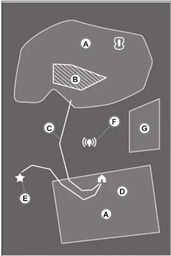
On the map you can install the objects that follow in the app:
• Work areas (A)
- Stay-out zones (B)
• Transport path (C)
• Charging station (D)
• Maintenance point (E)
• Reference station (F)
• Work area (Secondary area) (G)
flowchart
graph TD
    A["A"] --> B["B"]
    B --> C["C"]
    C --> E["E"]
    D["D"] --> E
    E --> F["F"]
    F --> G["G"]
    style A fill:#f9f,stroke:#333
    style B fill:#ccf,stroke:#333
    style C fill:#cfc,stroke:#333
    style D fill:#fcc,stroke:#333
    style E fill:#cff,stroke:#333
    style F fill:#ffc,stroke:#333
    style G fill:#cfc,stroke:#333
For a complete map installation, you must install a work area and a charging station on the map.
A work area is specified by virtual boundaries. Maximum work areas and secondary areas can be installed on a map.
There are two types of work areas:
• A work area that has a charging station in it or connected to it with a transport path where the product operates automatically.
• A secondary area is a work area with no charging station and no transport path. The product must be moved manually to and from the work area.
A transport path is a specified path between the docking point in front of the charging station and a work area. The product can operate automatically in this path, but does not cut grass. A transport path can temporarily be enabled and disabled in the app.
Stay-out zones can be made if there are areas where the product must not operate. A stay-out zone is specified by virtual boundaries. Stay-out zones can temporarily be enabled and disabled in the app.
A maintenance point is a specified position where the product can be parked at. This can for example be used for a service point where maintenance of the product is done. The maintenance point is connected to the docking point with a path.
To install objects on the map, operate the product with the appDrive installation to add waypoints on the map. Refer to To install objects on the map on page 117.
39.10.7.1 To install objects on the map
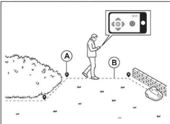
The waypoints (A) are positions that makes the virtual boundaries and paths (B). The lines are straight between the waypoints. Add a number of waypoints to make smooth curves. It is recommended to use as few waypoints as possible. For each work area and the related stay-out zones and transport path the total maximum number of waypoints are 800. Husqvarna recommends to add maximum 1000 waypoints for the complete installation of the map. You can adjust the positions of the waypoints in the app after the installation of the map. You can adjust the positions of the waypoints in the app after the installation of the map.

CAUTION: Do not lift and move the product between the waypoints when you install the map objects. Use appDrive for a correct installation.
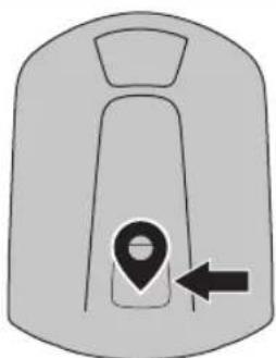
Note: The position of the waypoint when you install a work area or a stay-out zone is in the front left corner of the product.
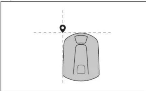
natural_image
Simple line drawing of a car or vehicle interior with a location marker (no text or symbols)Note: The position of the waypoint when you install a transport path or a path to a maintenance point is in the middle of the product between the drive wheels.
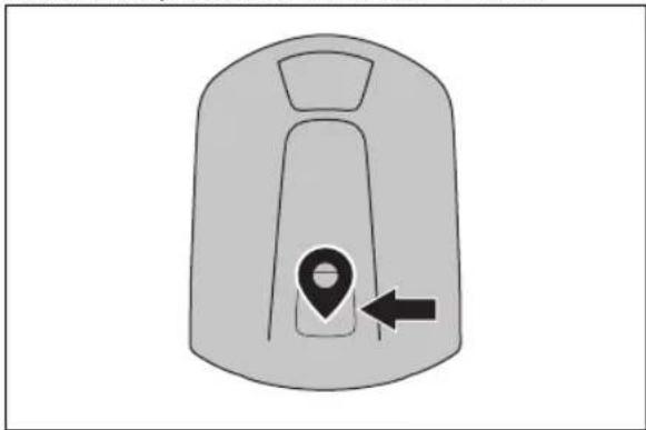
natural_image
Simple line drawing of a vehicle hood with a location pin and directional arrow (no text or symbols)- Make sure that you are near the product and connected to the product with the app with Bluetooth®.
- Make sure that the status is the appDrive. EPOSTM confirmed in
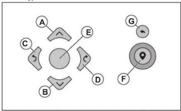
- Select the object you want to install and use the buttons in the appDrive installation to operate the product.
- Use the up button (A) to move the product forward.
- Use the down button (B) to move the product rearward.
- Use the left arrow button (C) to rotate the product to the left.
- Use the right arrow button (D) to rotate the product to the right.
- Use the center button (E) as a joystick to move and rotate the product in any direction.
- Use the waypoint button (F) to add a waypoint in the map.
- Use the undo button (G) to remove the latest waypoint.
flowchart
graph TD
    A["A"] --> C["C"]
    C --> B["B"]
    C --> E["E"]
    E --> D["D"]
    D --> F["F"]
    F --> G["G"]
    G --> Target["Target"]
    Target --> F
Note: Walk 2-3 m / 6.5-9.8 ft. behind the product when you operate the product with appDrive.
To make a work area
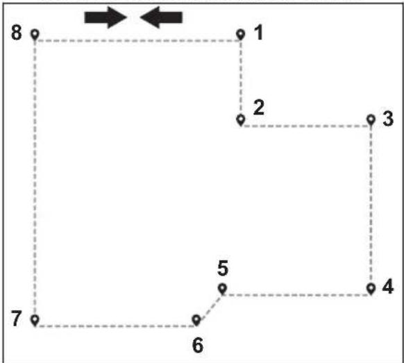
Minimum 3 waypoints are necessary to make a work area.
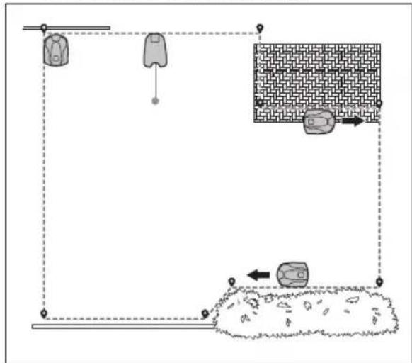
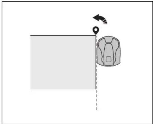
- Operate the product clockwise around the boundary of the work area.
- Add waypoints on the map. Add the waypoints minimum 3 cm / 1 in. from obstacles.
flowchart
graph TD
    A["Initial Setup"] --> B["Intermediate Processing"]
    B --> C["Final Output"]
    style A fill:#f9f,stroke:#333
    style B fill:#ccf,stroke:#333
    style C fill:#cfc,stroke:#333
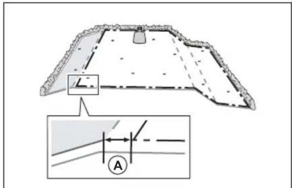
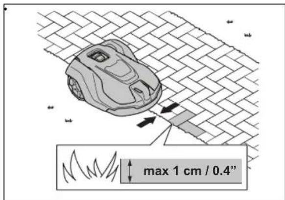
- Add a waypoint to make the product cut the grass at the edge between the lawn and the stone path. Make sure that you straddel the edge of the lawn and the stone path when you add a waypoint. The product can straddel the edge if the height of the stone path is maximum 1 cm / 0.4 in. in relation to the lawn.
- Add the waypoint at the outer corner to install the virtual boundary around a corner.
natural_image
Diagram showing a backpack and location pin with directional arrows, no text or symbols present- Do not set waypoints that make a virtual boundary go across itself in the same work area.
- Save the work area to automatically connect the first and last waypoint with a virtual boundary.
flowchart
graph TD
    1 --> 2
    2 --> 3
    3 --> 4
    4 --> 5
    5 --> 6
    6 --> 7
    7 --> 8
    8 --> 1
To make a stay-out zone
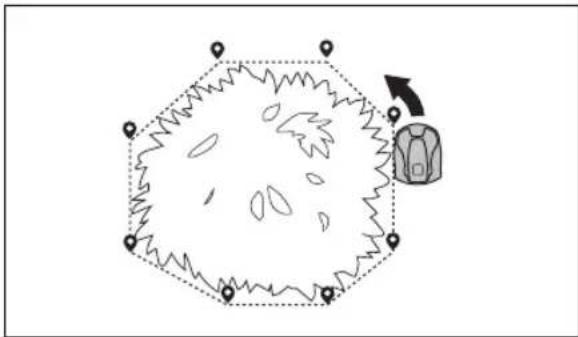
Minimum 3 waypoints are necessary to make a stay-out zone.
- Operate the product counterclockwise around the boundary of the stay-out zone.
- Add waypoints on the map. Add the waypoints minimum 3 cm / 1 in. from obstacles.
- Do not set waypoints that make a virtual boundary go across itself in the same stay-out zone.
- Save the stay-out zone to automatically connect the first and last waypoint with a virtual boundary.
natural_image
Diagram showing a hexagonal shape with internal patterns and a backpack icon, no text or symbols present.To make a transport path
- Operate the product and add waypoints on the map to install a transport path. Start in a work area minimum 1 m / 3.3 ft. from the virtual boundary.
- Do not install a transport path across a stay-out zone.
- Do not set waypoints that make the transport path go across the same transport path.
- Operate the product and add waypoints to connect the transport path to the docking point.
- Save the transport path to automatically connect the last waypoint to the docking point.
- Set the corridor width (A) for the transport path. The corridor width can be set to 2-5 m / 6.6-16.4 ft.
To make a maintenance point
- Operate the product and add waypoints on the map. Start to add waypoints at the position where you install the maintenance point. The first waypoint specifies the maintenance point.
- Operate the product and add waypoints to make a path to the charging station.
- Save the maintenance point to automatically connect the last waypoint to the docking point.
- Set the corridor width (A) for the maintenance point. The corridor width can be set to 2-5 m / 6.6-16.4 ft.
To reinstall the charging station on the map Reinstall the charging station on the map if you move or replace the charging station. You can also reinstall it if the robotic lawn mower cannot dock or connect to the charging station.
- Select map objects > Charging station in the app.
- Select Reinstall charging station and follow the instructions.
To reinstall the reference station on the map Reinstall the reference station on the map if you move or replace the reference station.
- Select map objects > Reference station in the app.
- Select Reinstall reference station and follow the instructions.
40 Maintenance
40.1 Introduction - maintenance
Do a check of the installation each year.
- Make sure that the post is tightly attached.
- Do a check of the tightening torques for all screws.
| Screw Tool Tightening torque (Nm) | ||
| Upper to lower chassis Torx 20 1.8 | ||
| Reference station to arm Torx 20 1.8 | ||
| Arm to post Hex key, 4 mm 5-6 | ||
| Arm, support bracket and post bracket Hex key, 4 mm 5-6 |
40.2 Clean the product

WARNING: Disconnect the product from the power supply before any maintenance or cleaning.

CAUTION: Do not use a high-pressure washer to clean the product. Do not use solvents for cleaning.
If necessary, clean the product with a moist cloth.
41 Troubleshooting
41.1 Introduction - troubleshooting
You can find all the troubleshooting messages in the Messages menu in . You can find more information on www.husqvarna.com.
41.2 Fault messages
The fault messages in the table below are shown in the Automower® Connect app. Speak to your Husqvarna representative if the same message shows frequently.
| Message Cause Action | ||
| No loop signal | The power supply or the low-voltage cable for the charging station is not connected. | If the LED indicator on the charging station is out, it shows that there is no power. Examine the power outlet connection and the residual-current device. Make sure that the low-voltage cable is connected to the charging station. |
| The power supply or the low-voltage cable for the charging station is damaged. | Replace the power supply or low-voltage cable. | |
| ECO modeis enabled and the LED indicator of the charging station flashes green. The product was started manually in the work area but the STOP button was not pushed before the product was moved from the charging station. The charging station signal is disabled and the product cannot enter the charging station. | Put the product in the charging station. Start the product. | |
| The product does not find the loop signal from the charging station. | Put the product in the charging station and make a new loop signal. | |
| The charging station in not installed correctly. | Install the charging station according to the instruction. Refer to To install the charging station on page 112. | |
| Interference from metal objects such as fences, reinforcement steel or buried cables near the charging station. | Change the position of the charging station. | |
| Outside work area | The work area slopes too much by the virtual boundary. | Make sure that the virtual boundary is installed correctly. |
| The transport path or the path to the maintenance point slopes too much. | Make sure that the transport path is installed correctly. Refer to To make a transport path on page 119. | |
| The product can not find the correct charging station signal because of interference with a loop signal from a different product installation nearby. | Put the product in the charging station and make a new loop signal. | |
| Interference from metal objects such as fences, reinforcement steel or buried cables near the charging station. | Change the position of the charging station. | |
| Empty battery | The product cannot find the charging station. | The product has no accurate position and cannot find the charging station. |
| There is an obstacle that prevents the product to find the charging station. | ||
| The battery is at the end of its life cycle. | Replace the battery. | |
| The antenna of the charging station is defective. | If the LED indicator on the charging station flashes red, the antenna of the charging station is defective. Speak to your approved servicing dealer. | |
| Map problem | There is no specified work area. Make a work area in the Automower 5 Connect app. Refer to To make a work area on page 118. | |
| The map object file is incorrect. Do a check of the map in the app. Adjust the map and save it. | ||
| Searching for position | Weak satellite signal to the reference station. | The satellite signal is temporary weak. The product will start to operate when the satellite signals are good. |
| Examine the installation of the reference station.. | ||
| Weak satellite signal to the product. The satellite signal is temporary weak. The product will start to operate when the satellite signal are good. | ||
| No accurate position from satellites | Weak satellite signal to the reference station. | Examine the installation of the reference station. |
| Weak satellite signal to the product. Examine if there is an object between the product and the sky that cause interference with the satellite signal. Remove the object or do a new installation to not include these parts in the work area. Refer to Installation of the map objects on page 116 | ||
| Reference station communication problem | The product is not connected to the reference station. | Do a pairing operation between the product and the reference station. |
| The reference station is not installed correctly. | Examine the installation of the reference station. | |
| The product does not receive the radio signal from the reference station in all areas where the product operates. | Test if the product has radio signal from the reference station in all of the work area. If not, make a new installation of the reference station or a new installation of the map. Refer to To install objects on the map on page 117. | |
| Power failure. Examine and correct the cause for the power failure of the reference station. | ||
| There is an error in the reference station and the LED indicator flashes red. | Disconnect the power to the reference station and connect it again to restart the reference station. If the problem stays, speak to your approved servicing dealer. | |
| There is interference with another reference station or other radio systems in the area. | Restart the product. If the problem stays, speak to your approved servicing dealer. | |
| Too many waypoints | There are too many waypoints in the current work area. | Do a new installation of the work area, stay-out zone and transport paths. Make less waypoints. Divide the current work area into more work areas. |
| Destination not reachable | There is no transport path between the charging station and the work area or maintenance point. | Make a transport path between the charging station and the work area or maintenance point. |
| The transport path is blocked and the product cannot go to the work area, charging station or maintenance point. | Make sure that the transport path is not blocked, or delete the transport path and make a new transport path. | |
| Multiple reference stations | There is more than one reference station near the work area. This can cause interference for the product from a different reference station. | Speak to your approved servicing dealer if the same problem occurs frequently. |
| EPOS plug-in not found | The EPOSTM Plug-in is defect or not installed correctly. | Restart the product. Make sure that the EPOSTM Plug-in is installed correctly and that the cable is connected. If the problem stays, speak to your approved servicing dealer. |
| Work area tampered | The charging station or the reference station was moved. | Do a new installation of the map. |
41.3 LED indicator lamp on the reference station
| Light Status | |
| Green flashing light Startup of the reference station. This can take some minutes. | |
| Green constant light In operation. | |
| Red flashing light The reference station is not working due to an error. Restart the product. If the problem stays, speak to your approved servicing dealer. | |
| White flashing light Firmware update is necessary. Speak to your local Husqvarna representative. | |
41.4 LED indicator lamp on the charging station
For a fully functional installation, the indicator lamp in the charging station must show a solid or flashing green light. If another color shows, follow the troubleshooting guide below.
There is more help on www.husqvarna.com. If you still need help, speak to your local Husqvarna representative.
| Light | Status |
| Green solid light Good signals. | |
| Green flashing light The signals are good and ECO mode is activated. | |
| Red flashing light Interruption in the charging station's antenna. Speak to your local Husqvarna representative. | |
| Red solid light Fault in the circuit board or incorrect power supply in the charging station. The fault must be correct by an authorized service technician. Speak to your local Husqvarna representative. | |
42 Storage and disposal
42.1 Storage
If you store the reference station indoors, keep the arm installed at the post or wall to be able to install the reference station on its original position again.
If you keep the reference station outdoors during the winter, we recommend you to keep the power supply connected.
42.2 Disposal
Obey the local recycling requirements and applicable regulations.
43 Technical data
43.1 Technical data
| Reference station dimensions | |
| Length, max length including plate for post installation cm/in. 36/13.8 | |
| Width, cm/in. 19/7.5 | |
| Height, cm/in. 36/13.8 | |
| Weight, reference station kg/lb 0.88/1.9 | |
| Weight, arm kg/lb 0.33/0.73 | |
| Reference station product data | |
| Type of Power Supply Unit ADP-40KR, FW7313/28/D/XX/Y/1.3 | |
| Power supply input, V AC 100-240 | |
| Power supply output, V DC 28 | |
| Power supply output, A 1.3 | |
| Low-voltage cable, length m/ft 20 / 66 | |
| IP-code reference station IPX5 | |
| IP-code power supply unit IP44 | |
| Power consumption, W 2 |
| Frequency Band Support | |
| Bluetooth® Frequency range (for service) 2400.0-2483.5 MHz | |
| SRD868 (Europe) 863-870 MHz | |
| SRD915 (Australia) 915-928 MHz | |
| SRD915 (New Zealand) 915-928 MHz | |
| Power Class | |
| Bluetooth® Output power (for service) 8 dBm | |
| SRD868 (Europe) 13 dBm | |
| SRD915 (Australia) 13 dBm | |
| SRD915 (New Zealand) 13 dBm | |
Full compatibility cannot be guaranteed between the product and other types of wireless systems such as remote controls and radio transmitters.
43.2 Registered trademarks
The Bluetooth ® word mark and logos are registered trademarks owned by Bluetooth SIG, inc. and any use of such marks by Husqvarna is under license.
44 Warranty
44.1 Warranty terms
Husqvarna® warranty covers this product's functionality for a period of 2 years from date of purchase. The warranty covers serious faults relating to materials or manufacturing faults. Within the warranty period, we will replace the product or repair it at no charge if the following terms are met:
- The product may only be used in compliance with the instructions in this Operator's Manual. This manufacturer's warranty does not affect warranty entitlements against the dealer/retailer.
- End-users or non-authorized third parties must not attempt to repair the product.
Examples of faults which are not included in the warranty:
- Damage caused by water seepage from using a high-pressure washer.
• Damage caused by lightning. - Damage caused by not using Husqvarna original spare parts and accessories.
- Damage caused by non-authorized changing or tampering with the product or its power supply.
If an error occurs with your Husqvarna product, please contact Husqvarna local representative for further instructions. Please have the receipt and the product's serial number at hand when contacting Husqvarna local representative.
45 Declaration of Conformity
For Declaration of Conformity, refer to the Operator's manual supplied with the robotic lawn mower.
Sommaire

flowchart
graph TD
    A["A"] --> C["C"]
    B["B"] --> C
    C --> D["Circle with dashed fill"]
    style C fill:#ccc,stroke:#333
    style A fill:#fff,stroke:#333
    style B fill:#fff,stroke:#333
    style C fill:#ccc,stroke:#333
    style D fill:#fff,stroke:#333
natural_image
Simple line drawing of a person standing under a dashed circle with a horizontal bar (no text or symbols)
natural_image
Technical line drawing of a robotic vacuum cleaner (no text or symbols)- Retirez les 4 vis (Torx20) et la plaque de protection.
natural_image
Technical line drawing of a car engine compartment with mounting flanges and a component highlighted (no text or symbols)natural_image
Technical diagram showing mechanical assembly with arrows indicating assembly steps (no text or labels present)natural_image
Technical line drawing of a mechanical component with a downward arrow indicating assembly or force (no text or symbols present)natural_image
Technical line drawing of a car interior showing internal components and wiring (no text or symbols)natural_image
Technical line drawing of a mechanical component with an arrow indicating direction (no text or symbols)natural_image
Technical illustration of a mechanical clamp or sensor assembly with a vertical post and side view (no text or symbols)natural_image
Technical line drawing of a mechanical component with directional arrows indicating movement or flow (no text or symbols present)natural_image
Technical diagram of a mechanical assembly with an inset showing a close-up of a component detail (no text or symbols present)natural_image
Technical diagram showing mechanical assembly with directional arrows and component details (no text or symbols)natural_image
Technical line drawing of a mechanical component with a labeled inset showing 'T20' (no other text or symbols)natural_image
Technical line drawing of a mechanical assembly with exploded view (no text or symbols)natural_image
Technical line drawing of a mechanical component with a cylindrical base and downward arrow indicating force or movement (no text or symbols)natural_image
Technical line drawing of a mechanical component with pins and connectors (no text or symbols)natural_image
Mechanical assembly diagram showing a lever mechanism with a close-up inset of the component detail (no text or labels)natural_image
Technical diagram showing mechanical assembly with a lever and directional arrow (no text or symbols)
natural_image
Simple line drawing of a car with a location pin and crosshair alignment lines (no text or symbols)natural_image
Simple line drawing of a vehicle hood with a location pin and directional arrow (no text or symbols)flowchart
graph TD
    A["Backpacks"] --> B["Hanging weights"]
    B --> C["Wooden area with brick pattern"]
    C --> D["Arrow right"]
    D --> E["Arrow left"]
    E --> F["Arrow down"]
natural_image
Diagram showing a backpack with a location pin and directional arrow, no text or symbols presentflowchart
graph TD
    A["Hexagon with jagged edges and location markers"] --> B["Upward arrow"]
    B --> C["Backpack icon"]
natural_image
Simple line drawing of a person sitting on a bench under a dashed circular threshold (no text or symbols)
natural_image
Technical line drawing of a robotic car with visible blades and mounting features (no text or symbols)natural_image
Technical line drawing of a car engine bay with mounting brackets and a component labeled 'L' (no text or symbols present)natural_image
Technical diagram showing mechanical assembly with arrows indicating connection to a component (no text or symbols present)natural_image
Technical line drawing of a mechanical component with a downward arrow indicating assembly or force (no text or symbols present)natural_image
Line drawing of a car front panel with visible wiring and connectors (no text or symbols)natural_image
Technical line drawing of a mechanical component with an arrow indicating direction (no text or symbols)natural_image
Technical illustration of a mechanical device with a lever and mounting bracket, showing no text or symbolsnatural_image
Technical line drawing of a mechanical housing component with directional arrows indicating movement (no text or symbols)natural_image
Technical diagram of a mechanical assembly with an inset showing a close-up of a component detail (no text or symbols present)natural_image
Technical diagram showing mechanical assembly with a lever and directional arrow (no text or symbols)natural_image
Technical line drawing of a mechanical component with a T20 indicator (no text or symbols on the diagram itself)natural_image
Exploded view diagram of a mechanical assembly with bolted components (no text or labels)natural_image
Technical line drawing of a mechanical component with a cylindrical base and downward arrow indicating force or motion (no text or symbols)natural_image
Technical line drawing of a mechanical component with pins and connectors (no text or symbols)natural_image
Technical diagram of a mechanical assembly with a component and close-up view (no text or labels)natural_image
Diagram of a mechanical assembly with a lever and directional arrow indicating motion (no text or symbols)
natural_image
Simple line drawing of a car hood with a location pin, no text or symbols presentnatural_image
Simple line drawing of a vehicle or container with a location pin and an arrow pointing to it (no text or symbols)natural_image
Diagram showing a backpack with a location pin and directional arrow, no text or symbols presentflowchart
graph TD
    A["Hexagon with jagged edges and scattered points"] --> B["Backpack icon"]
    style A fill:#f9f,stroke:#333
    style B fill:#bbf,stroke:#333

flowchart
graph TD
    A["A"] --> B["B"]
    B --> C["C"]
    C --> A
    style A fill:#f9f,stroke:#333
    style B fill:#ccf,stroke:#333
    style C fill:#cfc,stroke:#333
natural_image
Simple line drawing of a person sitting on a bench under a dashed circular threshold (no text or symbols)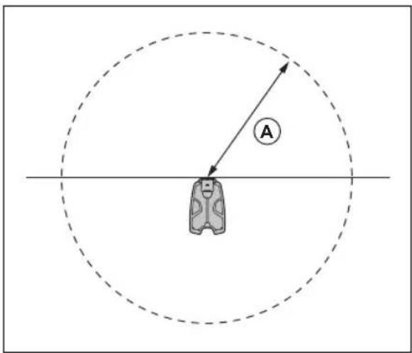
natural_image
Technical line drawing of a robotic vacuum cleaner (no text or symbols)natural_image
Technical line drawing of a car interior with mounting brackets and a component labeled 'Top Cover' (no text or symbols present)natural_image
Technical diagram showing engine components and wiring connections (no text or labels)natural_image
Technical line drawing of a mechanical component with a downward arrow indicating assembly or force (no text or symbols present)natural_image
Technical line drawing of a mechanical device with internal wiring and connectors (no text or symbols)natural_image
Technical line drawing of a mechanical component with an arrow indicating direction (no text or symbols)natural_image
Technical illustration of a mechanical device with a lever and mounting bracket, showing no text or symbolsnatural_image
Technical line drawing of a mechanical component with directional arrows indicating movement or flow (no text or symbols present)natural_image
Mechanical assembly diagram showing a mechanical component with a close-up inset of its internal structure (no text or labels)natural_image
Technical diagram showing mechanical assembly with a lever and directional arrow (no text or symbols)natural_image
Technical line drawing of a mechanical component with a labeled inset showing 'T20' (no other text or symbols)natural_image
Technical line drawing of a mechanical assembly with exploded view (no text or symbols)natural_image
Technical line drawing of a mechanical component with a cylindrical base and downward arrow indicating force or motion (no text or symbols)natural_image
Technical line drawing of a mechanical component with pins and mounting holes (no text or symbols)natural_image
Technical diagram of a mechanical assembly with an inset showing a close-up of a component detail (no text or symbols present)natural_image
Technical diagram showing mechanical assembly with a lever and directional arrow (no text or symbols)
natural_image
Simple line drawing of a vehicle or container with a location pin, no text or symbols presentnatural_image
Simple line drawing of a vehicle or container with a location pin and an arrow pointing to it (no text or symbols)natural_image
Diagram showing a backpack with a location pin and directional arrow, no text or symbols presentflowchart
graph TD
    A["Start"] --> B["Hexagon"]
    B --> C["Path to Right"]
    C --> D["Backplane Icon"]
    style A fill:#f9f,stroke:#333
    style D fill:#bbf,stroke:#333
flowchart
graph TD
    A["A"] --> B["B"]
    B --> C["C"]
    C --> A
    style A fill:#f9f,stroke:#333
    style B fill:#ccf,stroke:#333
    style C fill:#cfc,stroke:#333
natural_image
Simple line drawing of a person in a suit standing near a horizontal bar with a dashed circular boundary (no text or symbols)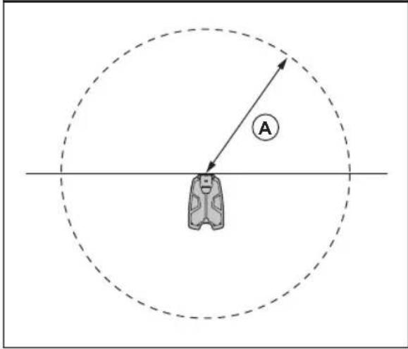
natural_image
Diagram showing a car with a circular arc and a triangular reflector, no text or symbols present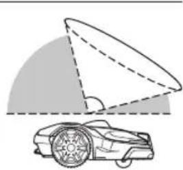
natural_image
Diagram showing a car with a curved roof and a shaded triangular area, no text or symbols present.natural_image
Technical line drawing of a mechanical device with no visible text or symbolsnatural_image
Technical line drawing of a vehicle chassis with mounting brackets and a highlighted component (no text or symbols)natural_image
Technical diagram showing engine compartment assembly with tool and valve (no text or labels)natural_image
Technical line drawing of a mechanical component with a downward arrow indicating force or movement (no text or symbols present)natural_image
Technical line drawing of a car airbag assembly with visible wiring and components (no text or symbols)natural_image
Technical line drawing of a mechanical component with an arrow indicating a process or assembly (no text or symbols present)natural_image
Technical illustration of a mechanical device mounted on a wall, showing a close-up and side view (no text or symbols)natural_image
Technical line drawing of a mechanical component with directional arrows indicating movement or flow (no text or symbols present)natural_image
Technical diagram of a mechanical assembly with an inset showing a close-up of a component detail (no text or symbols present)natural_image
Technical diagram showing mechanical assembly with directional arrows and component outlines (no text or symbols)natural_image
Technical line drawing of a mechanical assembly with exploded view (no text or symbols)natural_image
Technical line drawing of a mechanical component with a cylindrical base and downward arrow indicating force or motion (no text or symbols)natural_image
Technical line drawing of a mechanical component with two pins and a housing (no text or symbols)natural_image
Mechanical assembly diagram showing a lever mechanism with a close-up inset of the component detail (no text or labels)natural_image
Technical diagram showing mechanical assembly with directional arrows indicating movement (no text or symbols)
natural_image
Simple line drawing of a car with a location pin and crosshairs (no text or symbols)natural_image
Simple line drawing of a vehicle or container with a location pin and an arrow pointing to it (no text or symbols)natural_image
Diagram showing a backpack with a location pin and directional arrow, no text or symbols presentnatural_image
Diagram showing a hexagonal shape with jagged edges and scattered shapes, including a backpack icon and an arrow indicating direction (no text or symbols)
flowchart
graph TD
    A["A"] --> B["B"]
    B --> C["C"]
    C --> D["Circle"]
    style A fill:#f9f,stroke:#333
    style B fill:#ccf,stroke:#333
    style C fill:#cfc,stroke:#333
    style D fill:#fcc,stroke:#333
natural_image
Simple line drawing of a person in a suit standing near a horizontal bar, enclosed by a dashed circle (no text or symbols)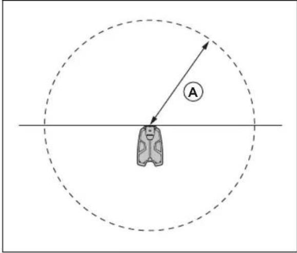
natural_image
Technical line drawing of a robotic vacuum cleaner (no text or symbols)natural_image
Technical line drawing of a car interior with mounting brackets and a mounted component (no text or symbols)natural_image
Technical diagram showing engine components and wiring connections (no text or symbols)natural_image
Technical line drawing of a mechanical component with a downward arrow indicating force or movement (no text or symbols present)natural_image
Technical line drawing of a car interior showing wiring and components (no text or symbols)natural_image
Technical line drawing of a mechanical component with an arrow indicating direction (no text or symbols)natural_image
Technical illustration of a mechanical clamp or sensor assembly with a dashed line indicating a reference point (no text or symbols present)natural_image
Technical line drawing of a mechanical component with directional arrows indicating movement or flow (no text or symbols present)natural_image
Technical line drawing of a mechanical component with a cylindrical base and downward arrow indicating force or motion (no text or symbols)natural_image
Technical line drawing of a mechanical component with two pins and a housing (no text or symbols)natural_image
Mechanical assembly diagram showing a lever mechanism with a close-up inset of the component detail (no text or labels)natural_image
Technical diagram showing mechanical assembly with directional arrows indicating movement (no text or symbols)
natural_image
Simple line drawing of a car with a location pin and dashed alignment lines (no text or symbols)natural_image
Simple line drawing of a device with a location pin and directional arrow (no text or symbols)natural_image
Diagram showing a backpack with a location pin and directional arrow, no text or symbols presentflowchart
graph TD
    A["Start"] --> B["Hexagon"]
    B --> C["Path to Right"]
    C --> D["Backplane Icon"]
    style A fill:#f9f,stroke:#333
    style D fill:#bbf,stroke:#333
flowchart
graph TD
    A["A"] --> B["B"]
    B --> C["C"]
    C --> A
    style A fill:#f9f,stroke:#333
    style B fill:#ccf,stroke:#333
    style C fill:#cfc,stroke:#333
natural_image
Simple line drawing of a person sitting on a platform with a dashed circular background and a horizontal bar (no text or symbols)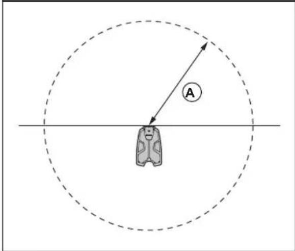
natural_image
Technical line drawing of a mechanical device with no visible text or symbolsnatural_image
Technical line drawing of a vehicle chassis with mounting brackets and a highlighted component (no text or symbols)natural_image
Technical diagram showing engine compartment assembly with tool and valve (no text or labels)- Instale o plug-in EPOS com 4 parafusos.
- Instale a cobertura superior.
natural_image
Technical line drawing of a mechanical component with a downward arrow indicating force or movement (no text or symbols present)natural_image
Technical line drawing of a car rearview assembly with visible wiring and components (no text or symbols)natural_image
Technical line drawing of a mechanical component with an arrow indicating direction (no text or symbols)natural_image
Technical illustration of a mechanical clamp or sensor assembly with mounting bracket (no text or symbols)natural_image
Technical line drawing of a mechanical bracket with directional arrows indicating movement or force (no text or symbols present)natural_image
Technical diagram of a mechanical assembly with an inset showing a close-up of a component detail (no text or symbols present)natural_image
Technical diagram showing mechanical assembly with a lever and directional arrow (no text or symbols)natural_image
Technical line drawing of a mechanical component with a labeled inset showing 'T20' (no text or symbols on the diagram itself)natural_image
Technical line drawing of a mechanical assembly with exploded view (no text or symbols)natural_image
Technical line drawing of a mechanical component with a cylindrical base and downward arrow indicating force or motion (no text or symbols)natural_image
Technical line drawing of a mechanical component with pins and mounting holes (no text or symbols)natural_image
Mechanical assembly diagram showing a mechanical component with a close-up inset of its internal structure (no text or labels)natural_image
Technical diagram showing mechanical assembly with directional arrows and component outlines (no text or symbols)
natural_image
Simple line drawing of a car with a location pin and crosshair alignment lines (no text or symbols)natural_image
Simple line drawing of a vehicle or container with a location pin and an arrow pointing to it (no text or symbols)flowchart
graph TD
    A["Container"] --> B["Storage"]
    B --> C["Storage with Storage"]
    C --> D["Storage with Storage"]
    D --> E["Storage with Storage"]
    style A fill:#f9f,stroke:#333
    style B fill:#ccf,stroke:#333
    style C fill:#cfc,stroke:#333
    style D fill:#fcc,stroke:#333
natural_image
Diagram showing a backpack with a location pin and directional arrow, no text or symbols presentflowchart
graph TD
    A["Hexagon with zigzag edges and scattered points"] --> B["Backplane icon"]
    B --> C["Arrow indicating direction"]
- Referenčna postaja
- Roka
- Podporni nosilec
- Majhna vratnica nosilca, za steber mer 32-44 mm/1.26-1.73 palci
- Velika vratnica nosilca, za steber mer 44-55 mm/44-55 palci
-
Automower ® EPOS™ Plug-in
-
Vijaki
- Vijaki
- Podložke
- Napajalnik 78
- Nizkonapetostni kabel
- Navodila za uporabo
101.1.5 Pregled sistema

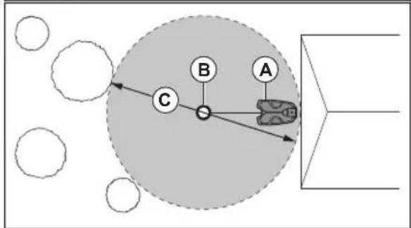
flowchart
graph TD
    A["A"] --> B["B"]
    B --> C["C"]
    C --> D["Circle"]
    style C fill:#ccc,stroke:#333
    style A fill:#fff,stroke:#333
    style B fill:#fff,stroke:#333
    style C fill:#ccc,stroke:#333
    style D fill:#fff,stroke:#333
natural_image
Simple line drawing of a person sitting on a bench under a dashed circular threshold (no text or symbols)
natural_image
Technical line drawing of a robotic vacuum cleaner (no text or symbols)- Odstranite 4 vijake (Torx20) in pokrov.

natural_image
Technical line drawing of a car interior with overhead mounting bracket and directional arrow (no text or symbols)natural_image
Technical diagram showing engine compartment assembly with valve and fan components (no text or labels)natural_image
Technical line drawing of a mechanical component with a downward arrow indicating force or movement (no text or symbols present)- Magnite zgornji del polnilne postaje.
- S kabli namestite nastavek na svoje mesto.
- Kabel priklopite na polnilno postajo.
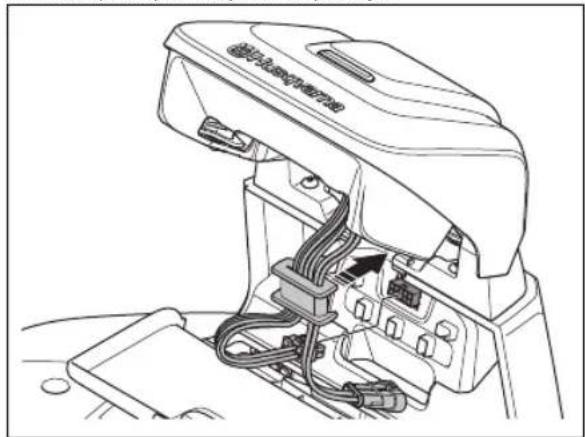
natural_image
Technical line drawing of a car airbag assembly with visible wiring and components (no text or symbols)natural_image
Technical line drawing of a mechanical component with an arrow indicating direction (no text or symbols)natural_image
Technical illustration of a mechanical device with a dashed line indicating a reference point, shown from two different angles (no text or symbols present)natural_image
Technical line drawing of a mechanical component with directional arrows indicating movement or flow (no text or symbols present)natural_image
Technical diagram of a mechanical assembly with an inset showing a close-up of a component detail (no text or symbols present)natural_image
Technical diagram showing mechanical assembly with directional arrows indicating movement (no text or symbols)- Zategnite vijak (Torx 20) na roki referenčne postaje.
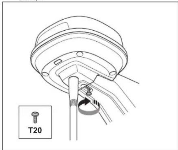
natural_image
Exploded view diagram of a mechanical assembly with bolted components (no text or labels)natural_image
Technical line drawing of a mechanical component with a cylindrical base and downward arrow indicating force or movement (no text or symbols)natural_image
Technical line drawing of a mechanical component with pins and mounting holes (no text or symbols)natural_image
Technical diagram of a mechanical assembly with an inset showing a close-up of a component detail (no text or symbols present)natural_image
Technical diagram showing mechanical assembly with a lever and directional arrow (no text or symbols)- Zategnite vijak (Torx 20) na roki referenčne postaje.
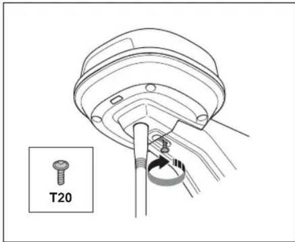

natural_image
Simple line drawing of a car hood with a location pin (no text or symbols)natural_image
Simple line drawing of a vehicle or container with a location pin and directional arrow (no text or symbols)natural_image
Diagram showing a backpack with a location pin and directional arrow, no text or symbols presentAUTOMOWER® is a trademark owned by Husqvarna AB.
Copyright © 2023 HUSQVARNA. All rights reserved.
www.husqvarna.com
Bruksanvisning i original Originale instruktioner Alkuperäiset ohjeet Originale instruksjoner
Original instructions Instructions d'origine
Originele instructies Istruzioni originali Instrucciones originales Originalanweisungen Instruções originais Izvirna navodila


- Göra EPOS™ -konfigurationen
- Sådan oprettes en transportsti
- Safety
- Safety definitions
- General safety instructions
- Safety instructions for installation
- Safety instructions for maintenance
- In the event of a thunderstorm
- Introduction
- Introduction
- Support
- Product description
- System description
- System overview
- Symbols on the product
- Symbols in the app
- Installation
- Introduction - Installation
- Primary components for installation
- To prepare for installation
- To examine where to put the reference station
- To examine where to put the power supply
- To examine where to put the charging station
- To examine where to put the power supply
- To examine where to install the virtual boundaries
- To install map objects near buildings and trees
- Passages
- To install the map objects in a slope
- To install the product
- Installation tools
- To install the EPOS plug-in
- To do the EPOS TM setup
- Automower® Connect
- Installation of the charging station
- Installation of the map objects
- To install objects on the map
- To make a work area
- To make a stay-out zone
- To make a transport path
- To make a maintenance point
- Maintenance
- Introduction - maintenance
- Clean the product
- Troubleshooting
- Introduction - troubleshooting
- Fault messages
- LED indicator lamp on the reference station
- LED indicator lamp on the charging station
- Storage and disposal
- Storage
- Disposal
- Technical data
- Technical data
- Registered trademarks
- Warranty
- Warranty terms
- Declaration of Conformity
- Sommaire
- Pregled sistema
Brand : HUSQVARNA
Model : Automower EPOS Plugin Kit
Category : Robotic mower