Tiper 2 - Pump ESPA - Free user manual and instructions
Find the device manual for free Tiper 2 ESPA in PDF.

| Product type | Single-stage centrifugal pump for hydromassage |
| Brand | ESPA |
| Model | Tiper 2 |
| Power supply | 230 V / 50 Hz / Single-phase |
| Input power (P1) | 0.7 kW |
| Rated current | 3 A |
| Capacitor | 12 µF / 450 V |
| Thermal protection | Built-in (Klixon) |
| Maximum pressure | 10 mH2O |
| Flow rate | 50 to 300 L/min |
| Liquid temperature | 4°C to 50°C |
| Ambient temperature | 0°C to 40°C |
| Protection degree | IPX5 |
| Motor insulation class | F |
| Operation type | Continuous (S1) |
| Maintenance | Clean with damp cloth, no regular maintenance |
| Safety | 30 mA residual current device, mandatory grounding |
| Use | Clean water, free of suspended solids |
| Priming | Required before starting |
| Certifications | CE, European directives (Machinery, EMC, Low Voltage) |
Frequently Asked Questions - Tiper 2 ESPA
User questions about Tiper 2 ESPA
0 question about this device. Answer the ones you know or ask your own.
Ask a new question about this device
Download the instructions for your Pump in PDF format for free! Find your manual Tiper 2 - ESPA and take your electronic device back in hand. On this page are published all the documents necessary for the use of your device. Tiper 2 by ESPA.
USER MANUAL Tiper 2 ESPA
natural_image
Technical line drawing of an electric motor with mounting base and housing (no text or symbols)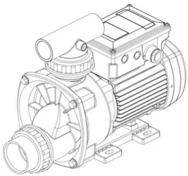
natural_image
Technical line drawing of an electric motor with visible shaft, housing, and mounting base (no text or labels)EN Instruction manual.... 10 (Translation from the original Spanish)
EN: EVIDENCE OF CONFORMITY
We declare, under our responsibility, that the products in this manual comply with the following directives and standards:
- Directive 2006/42/EC (Machine Security): Standard EN 809 and EN 60204-1
- Directive 2014/30/EU (Electromagnetic compatibility): Standard EN 61000-6-1 y EN 61000-6-3
- Directive 2014/35/EU (Low voltage): Standard EN 60335-1, EN 60335-2-41 and EN 60335-2-60
- Directive 2009/125/EC (ecological design): Regulation (EU) 2019/1781 electrical motors and variable speed drives. Standard EN 60034-30.
- Directive 2012/19/EU (on waste electrical and electronic equipment (WEEE)): Standard EN 50419:2006 about marking of electrical and electronic equipment.
- Directive 2011/65/UE (Restriction of hazardous substances): Standard EN 50581.
FR : DECLARATION DE CONFORMITÉ
EVIDENCE OF CONFORMITY
We declare, under our responsibility, that the products in this manual comply with the following directives and standards:
- Supply of Machinery (Safety) Regulations 2008: Standard BS 809 and BS 60204-1
- Electromagnetic Compatibility Regulations 2016: Standard BS 61000-6-1 and BS 61000-6-3.
- Electrical Equipment (Safety) Regulations 2016: Standard BS 60335-1 and BS 60335-2-41.
- The Ecodesign for Energy-Related Products and Energy Information (Amendment) (EU Exit) Regulations 2019: Standard BS 60034-30.
- The Restriction of the Use of Certain Hazardous Substances in Electrical and Electronic Equipment Regulations 2012. Standard BS 50581.
Banyoles, January 11th 2021
Josep Unyó (Technical Manager)
ESPA 2025, SL
Ctra. de Mieres, s/n – 17820 Banyoles
Girona - Spain
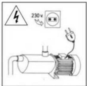
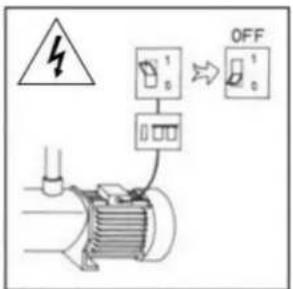
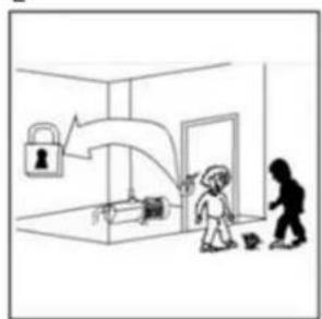
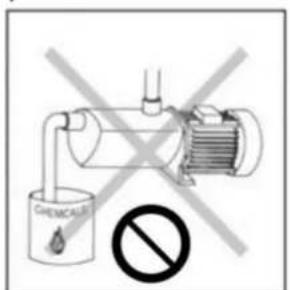
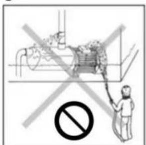
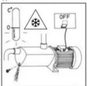
Damage prevention and safety instructions (See figure 4)
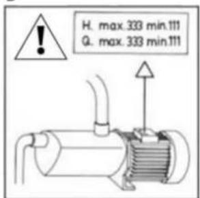
| A | Warning! Observe limitations of use. |
| B | The name plate voltage must be the same as the mains voltage. |
| C | Connect the pump to the mains via an omnipolar switch with at least a 3 mm opening between contacts.Install a high-sensitivity differential switch (0.03A) as extra protection against lethal electric shocks. |
| D | If the supply cord is damaged, it must be replaced by an A.T.S. |
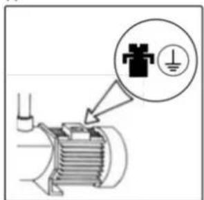
| E | Connect the pump to the ground. |
| F | Use pump only within performance limits indicated or the name plate. |
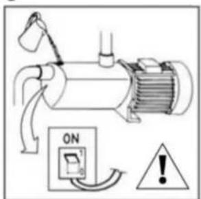
| G | Remember to prime pump. |
| H | Check for motor self-ventilation. |
| I | This apparatus may be used by children 8 years or older and persons with reduced physical, sensory or mental capacities, or lacking experience and knowledge, if they are supervised or receive adequate training on the safe use of the apparatus and understand the dangers.Children should not be allowed to play with the apparatus.Children should not perform the ordinary cleaning and maintenance tasks without supervision. |
| J | Be careful with hazardous liquids and environments. |
| K | Caution! Look out for accidental leaks.Do not expose pump to bad weather. |
| L | Caution! Avoid icing.Cut out power supply before servicing pump. |
Contents
Safety precautions....10
- General information....11
- Handling 11
- Installation 11
3.1. Fixing....11
3.2. Suction pipe assembly 11
3.3. Discharge pipe assembly 11
3.4. Electrical connection....11
3.5. Pre-start checks 12
- Starting 12
- Maintenance....12
- Disposing of the product.....12
- Nameplate 12
- Possible faults, causes and solutions ..... 13
- Technical data....13
- List of main components .....40
- Wiring diagrams ....41
- Illustrations ......42
Safety precautions
This symbol together with one of the following words “Danger” or “Warning” indicates the risk level deriving from failure to observe the prescribed safety precautions:

DANGER risk of electric shock
Warns that failure to observe the pre cautions involves a risk of electric shock.

DANGER
Warns that failure to observe the pre cautions involves a risk of damage to persons and/or things.

WARNING
Warns that failure to observe the pre cautions involves the risk of damaging the pump and/or the facility
1. GENERAL INFORMATION
Please observe the following instructions to achieve the best pump performance possible and a trouble free installation.

Read these instructions before installing the pump. Save them for future reference.
These are single-stage, centrifugal electric pumps designed to operate with compact hydromassage equipment. They are equipped with a total-emptying system to prevent the discharge of residual liquid in each start-up.
These pumps are designed to operate with clean water, free from particles in suspension and with a maximum temperature of 50^ C.

Correct pump operation is assured providing the instructions on electrical connection, installation and use are strictly adhered to.

Failure to adhere to the instructions can result in premature failure of the pump and voiding of the warranty.
2. HANDLING
The pumps are supplied suitably packaged to prevent damage in transit. Before unpacking, check that the packaging has not been damaged or deformed,

Lift and handle the product with care and with the right tools.
3. INSTALLATION
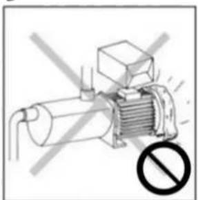
These pumps are designed for indoor use.
The pump should be protected from possible flooding and receive dry ventilation.
3.1. Fixing
The pump should be installed on a solid, horizontal base, secured by screws or bolts and using the existing holes in the mount.
3.2. Suction pipe assembly
The suction pipe must be of the same or greater diameter than the pump inlet and installed in an upward inclination to prevent trapped air pockets forming.
The suction pipe of the pump should be as short as possible.
3.3. Discharge pipe assembly
It is recommended to use pipes with a diameter equal or greater than the pump outlet. This will reduce loss of head caused by friction in longer pipe runs.
Pipework must be supported and their weight must not rest on the pump.
3.4. Electrical connection

The electrical installation must have a multi-pole isolator with minimum 3mm contact openings,
The protection of the system will be based on a differential switch ( fn = 30mA )
The supply power cable must correspond at least to the type H07 RN-F (according to 60245 IEC 66) and having terminals.
The electric connection must be carried out by qualified staff following strictly the "EN 60335-2-60" standard.
Be sure that the earth cable connection is correctly made.
Be sure that the earth bonding lug between the bath and the pumps is correctly made.

Single-phase motors have built-in thermal protection.
Follow instructions given on fig.1 for correct electrical connection.
3.5. Pre-start checks

Ensure the voltage and frequency of the supply corresponds to the values indicated on the electrical data label.
Ensure that the pump shaft is rotating freely.
The hydromassage assembly should be equipped with a system to prevent the pump from starting up if a minimum water level is not present. The pump should wait until the water reaches that level.
Check all joints and connections for leaks.
THIS PUMP MUST NEVER BE DRY RUN.
4. STARTING
Ensure all valves in the pipework are open.
Apply voltage to the motor and suitably adjust the jets to obtain the desired flow.
Viewings from the fan ensure that the rotation of the motor is clockwise.
Ensure that the absorbed current is the same or lower than the maximum shown on the name plate. Adjust the thermal relay if is necessary.
If the pump fails to operate refer to the possible faults, causes and solutions list for assistance.
5. MAINTENANCE
Under normal conditions these pumps require no special or planned maintenance.
Clean the pump with a damp cloth without using harsh products.

If the pump is not to be operated for a long period it is recommended to remove it from the installation, drain down and store in a dry, well ventilated place.
ATTENTION: In the event of faults or damage occurring to the pump, repairs should only be carried out by an authorised service agent.
The Official Technical Services list is in www.espa.com.
6. DISPOSING OF THE PRODUCT
When the pump is eventually disposed of, please note that it contains no toxic or polluting material. All main components are material identified to allow selective disposal.
This product or parts of it must be disposed of in an environmentally sound way, use the waste collection service. If this is not possible, contact the nearest ESPA service workshop.
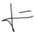
- PLATE SHOWING CHARACTERISTICS
text_image
9 1 TIPER 70M 2 230 50 14767/STD 3 Q(l/min): 50-300 4 H(m): 9-1 5 230V 1~50Hz 6 12μF - 450V 7 C E 8 17 16 2020W01-00003 Thermally protected Tmax: 50°C Hmax: 10m I:3A P1: 0.7kW ESPA 2025 S.L. 17820 Banyoles (MADE IN SPAIN) Is.KL.F S1 10 11 12 13 14 15DESCRIPTION
| 1 | Item reference |
| 2 | Voltage + frequency + item specifications |
| 3 | Flow |
| 4 | Pressure |
| 5 | Nominal voltage, no. stages, alternate current symbol and frequency |
| 6 | Capacitor (Single-phase model) |
| 7 | EC mark |
| 8 | Humidity protection level |
| 9 | Maximum pressure |
| 10 | Year and week of manufacture + Pump serial no. |
| 11 | Thermal protection incorporated indicator |
| 12 | Max. liquid temperature |
| 13 | Electric pump unit absorbed power(P1) |
| 14 | Designated motor insulation |
| 15 | Continuous operation symbol |
| 16 | Maximum nominal intensity at nominal voltage |
| 17 | Name and address of vendor responsible for the product |
8. POSSIBLE FAULTS, CAUSES AND SOLUTIONS
1) The pump does not deliver any flow.
2) The pump does not start.
3) The motor starts and stops automatically (klixon).
4) Insufficient flow.
5) The Pump is noisy.
| 1 | 2 | 3 | 4 | 5 | POSSIBLE PROBLEM | SOLUTIONS |
| X | X | Incorrect voltage | Verify the voltage specified on the nameplate and that of the mains | |||
| X | Thermal relay tripped | Reset thermal relay | ||||
| X | X | Diameter of suction line smaller than required | Correctly dimension suction line | |||
| X | X | Lack of water in the hydromassage assembly | Fill the hydromassage assembly with water | |||
| X | Incorrect pump attachment | Attach the pump correctly | ||||
| X | Lack of power | Reset the fuses | ||||
| X | Jets or pipes clogged | Clean them properly | ||||
| X | X | Air entry trough suction line | Verify condition of connectors and gaskets of suction line | |||
| X | X | Pump seized | Contact qualified personnel | |||
| X | Drop in water level | Make up to level |
9. TECHNICAL DATA
Liquid temperature: 4°C - 50°C
Ambient temperature: 0°C - 40°C
Storage temperature: -10°C - 50°C
Ambient relative humidity, max.: 95%
Motor class I.
Other data see Figure 2.
6. AFVOEREN VAN HET PRODUCT
text_image
Technical schematic diagram of a mechanical device with numbered components for identification| ES | EN | FR | DE | IT | |
| 1 | Tapa aspiración | Suction cover | Fond d'aspiration | Saugdekel | Coperchio, lato aspirante |
| 2 | Racor impulsión | Impeller connector | Raccord refoulement | Druckstutzen | Raccordo di mandata |
| 3 | Condensador | Capacitor | Condensateur | Kondensator | Condensatore |
| 4 | Tapa ventilador | Fan cover | Capot de ventilateur | Lüferhaube | Cuffia della ventola |
| 5 | Ventilador | Fan | Ventilateur | Lüferrad | Ventola |
| 6 | Racor aspiración | Suction connector | Raccord aspiration | Saugstutzen | Raccordo di aspirazione |
| 7 | Rodete | Impeller connector | Roue | Laufrad | Girante |
| 8 | Retén mecánico | Mechanical seal | Garniture mécanique | Gleintringdichtung | Tenuta meccanica |
| 9 | Cuerpo bomba | Pump casing | Corps de pompe | Pumpengehäuse | Corpo della pompa |
| 10 | Rodamiento | Anti-friction bearing | Roulement | Wälzager | Cusinetto a rolamento |
| 11 | Eje del motor | Motor shaft | Arbre de moteur | Motorwelle | Albero del motore |
| 12 | Estator | Stator | Stator | Stator | Estator |
| 13 | Pie | Foot | Pied | Fub | Piede |
| PT | NL | RU | AR | |
| 1 | Tapa aspiração | Zuigdeksel | Всасывающий патрубок | غطاء شقط |
| 2 | Adaptator de impulsão | Waaier connector | Фитинг напорного патрубка | مناسب |
| 3 | Condensador | Condensator | Конденсатор | مكُف |
| 4 | Tampa do ventilador | Ventilatorkap | Кожух вентилятора | ة غطاء |
| 5 | Ventilador | Ventilator | Вентилятор | مروحة |
| 6 | Adaptador de aspiração | zuig connector | Фитинг всасывающего патрубка | مناسب |
| 7 | Impulsão | Rotor | Рабочее колесо | المكره |
| 8 | Fecho mecânico | Glijringpakking | Механическое уплотнение | ة ختم |
| 9 | Corpo de bomba | Pompbehuizing | Корпус насоса | ة جسم |
| 10 | Rolamento | Lager | Подшипник | سناد |
| 11 | Veio de motor | Motoras | Вал двигателя | ت رم Cum |
| 12 | Stator | Stator | Статор | ت الجزء |
| 13 | Pé | Voet | Опора | سفح |
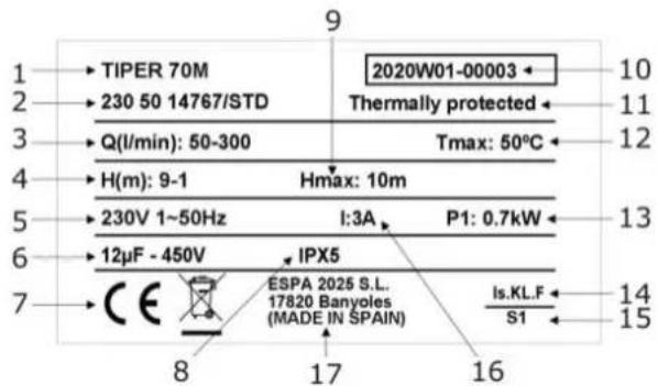
Fig.1 / Abb.1 / Afb.1 / Puc.1 / 1 لشکل
ALIMENTACIÓN MONOFÁSICA SINGLE PHASE SUPPLY ALIMENTATION MONOPHASÉE EINPHASENSTROM ALIMENTAZIONE MONOFASICA ALIMENTAÇÃO MONOFASICA EENFASIGE VOEDING ОДНОФАЗНОЕ ПОДКЛЮЧЕНИЕ تزويد واحدة مرحلة على
text_image
M 1~ 1 2 6 3 4 N L 5| 1. | ROJO | 2. | BLANCO | 3. | NEGRO | 4. | CONDENSATOR | 5. | LINEA | 6. | PROTECTOR TÉRMICO |
| RED | WHITE | BLACK | CAPACITOR | LINE | MOTOR RELAY | ||||||
| ROUGE | BLANC | NOIR | CONDENSATEUR | TENSION | PROTECTEUR MOTEUR | ||||||
| ROT | WEISS | SCHWARZ | KONDENSATOR | SPENNUNG | MOTORSCHUTZ | ||||||
| ROSSO | BIANCO | NERO | CONDENSATORE | LINEA | PROTETTORE DEL MOTORE | ||||||
| VERMELHO | BRANCO | PRETO | CONDENSADOR | LINHA | MOTO PROTECTOR | ||||||
| ROOD | WIT | ZWART | CONDENSATOR | LIJN | THERMISCHE ZEKERING | ||||||
| KPACHНЫЙ | БЕЛЫЙ | ЧЕРНЫЙ | КОНДЕНCATOP | ФАЗА | ТЕПЛОВАЯ ЗАЩИТА | ||||||
| أحمر | أبيض | أسود | مكتف | الجهد الكهربى | حامي المحرك |
Fig. 2 / Abb. 2 / Afb. 2 / Pnc. 2 / 2
text_image
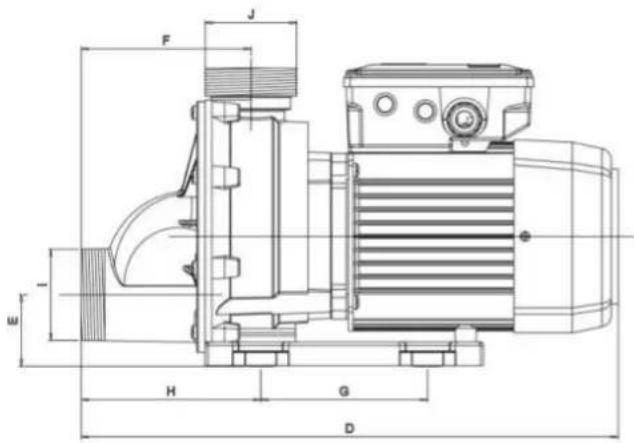
F J H G D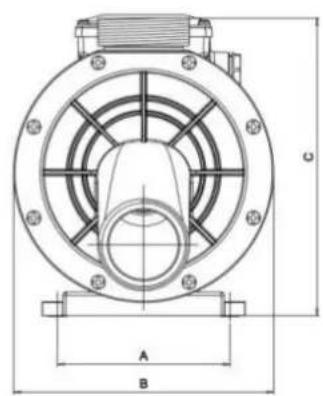
text_image
A B C| 50 Hz | Q max. [l/min] | H max. [m] | A 1~230V | C μF | P1 [kW] | IP | η(%) | dBa ±1 | A [mm] | B [mm] | C [mm] | D [mm] | E [mm] | F [mm] | G [mm] | H [mm] | I | J | [kg] | ||
| TIPER 70M | 300 | 10 | 3 | 12 | 0,7 | 55 | 37 | <70 | 100 | 155 | 182 | 312 | 47 | 88 | 88 | 130 | 2 1/4" | 2 1/4" | 3,9 | ||
| TIPER 90M | 345 | 11 | 3,8 | 12 | 0,9 | 55 | 37 | <70 | 100 | 155 | 182 | 312 | 47 | 88 | 88 | 130 | 2 1/4" | 2 1/4" | 4,4 | ||
| TIPER2 75M | 380 | 13 | 5 | 16 | 1,2 | 55 | 42 | 71 | 124 | 187 | 215 | 378 | 50 | 120 | 120 | 130 | 2 1/4" | 2 1/4" | 3,9 | ||
| TIPER2 125M | 430 | 14,5 | 6,3 | 16 | 1,5 | 55 | 42 | 72 | 124 | 187 | 215 | 378 | 50 | 120 | 120 | 130 | 2 1/4" | 2 1/4" | 4,4 | ||
| 60 Hz | Q max. [l/min] | H max. [m] | A 1~115V | 220V | C [μF] | P1 [kW] | IP | η(%) | dBa ±1 | A [mm] | B [mm] | C [mm] | D [mm] | E [mm] | F [mm] | G [mm] | H [mm] | I | J | ||
| TIPER 70M | 300 | 9,5 | 5,7 | 3,2 | 30 | 12 | 0,65 | 55 | 37 | <70 | 100 | 155 | 182 | 312 | 47 | 88 | 88 | 130 | 2 1/4" | 2 1/4" | 3,9 |
| TIPER 90M | 333 | 10 | 7 | 3,9 | 30 | 12 | 0,8 | 55 | 37 | <70 | 100 | 155 | 182 | 312 | 47 | 88 | 88 | 130 | 2 1/4" | 2 1/4" | 4,4 |
text_image
Diagram illustrating a mechanical device with an ABC-related document, showing internal components and a circular icon with a person.A
text_image
230 V AB

text_image
OFFC
text_image
Diagram showing electrical hazard symbol, switch, and OFF button with labeled componentsD
text_image
Diagram showing a mechanical component with an electrical symbol and a warning icon, likely indicating a hazard or hazard.E
text_image
H. max. 333 min.111 Q. max. 333 min.111F
text_image
Diagram showing a mechanical device with ON/OFF warning symbol and warning signG
natural_image
Diagram of an electric motor with a prohibition symbol (no text or labels present)H
natural_image
Simple line drawing of a room with a person, a child, and a lock (no text or symbols)I
text_image
CHEMICAL No]
text_image
Safety warning illustration showing a person spraying disinfection with a 'No' symbol belowK
text_image
Diagram of an experimental setup with labeled components including test tube, warning symbol, and OFF buttonL
ESPA 2025, S.L.
C/ Mieres, s/n - 17820 BANYOLES
GIRONA - SPAIN
www.espa.com